1
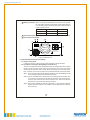
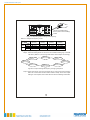
040-06-409-042-EH-0614.pdf
ISI-501 Series
Off-Grid Solar Inverter
User Manual
040-06-409-042-EH-0614.pdf
Off-Grid Solar Inverter
User Manual
Table of Contents
1.Safety Guidelines ................................................................................... 1
2.Introduction ............................................................................................ 1
2.1 Features........................................................................................... 1
2.2 Main Specification ............................................................................ 2
3.User Interface Panel ............................................................................... 2
3.1 Front Panel ...................................................................................... 2
3.2 LED indicator on Front Panel ............................................................ 3
3.3 Rear Panel ....................................................................................... 3
4.Output Voltage and Frequency Settings .................................................. 4
4.1 Initial Factory State .......................................................................... 4
4.2 Procedure to Change Output Voltage and Frequency......................... 4
5.Operating ............................................................................................... 6
6.Protection .............................................................................................. 7
6.1 Input Protection ............................................................................... 7
6.2 Output Protection ............................................................................. 7
7.Installation & Wiring ................................................................................ 7
8.Troubleshooting ...................................................................................... 10
9.Warranty ................................................................................................ 10
Mar. 2014 Version 1
040-06-409-042-EH-0614.pdf
1.Safety Guidelines (Please read through this manual before assembling the Inverter)
‧Risk of elect rical sho ck and e nerg y hazard. All failures sho uld be examined by a
qualified tec hnician. Ple ase do n ot remove the case of the inv erte r by you rself!
‧Plea se d o no t install the inverter in places with hig h moisture o r nea r wa ter.
‧Please do no t install the inverter in places with high am bie nt tempe rature, u nde r
direct sunlight, or near fire source.
‧Ple a se o nly co n ne c t ba t ter i es w ith t he s am e b ra nd a nd mo d el n um b er i n o n e
battery bank. Using batteries from different manufacturers or different capacities
is st rictl y prohib ited!
‧Never allow a spark or fla me in the vic inity of the batteries.
‧Mak e su re th e airflow thr oug h the fan is not o bstr ucted on bot h sid es (fron t and
back) of the inverter. (Ple ase keep any objects clear from the fan at least 15cm)
‧Please do not stack any objects on the inverter as it may im pede heat dissipation.
‧Please t urn o ff th e inverter throug h th e po wer ON /OFF sw itch , before rem ovin g
the battery.
WARNING: Batteries will have aging problems after years of operation.
It is suggeste d to exe cute re g ul ar battery maintena nce
(e.g. every year). Once aged, the batteries should be changed
by a p rofessional technician, or the failed batteries may
cause fire or other hazards.
Inverter
Inverter
Don't
disasse mble
Keep away from
moistu re
Inverter
Keep away from
fire or high
temperatur e
Don't stack on
the inverter
Inve rter
K eep good
ve ntilation
2.Introduction
‧ISI-501 is a true sine wave DC/AC off-grid inverter equipped with a solar charger
(with Maximum P ower Point Tracking, or MPPT) which is digitally controlled by an
adva nce d microp rocesso r an d in corp ora tes a hig h fre que ncy des ign. This hig h
performance inverter can be paired with both battery a nd PV m odu les / pan els.
‧ISI-501 can provide 500W pure sine wave output continuously, 550W for 1 minute,
and sustain a peak lo ad of 1000W as long as 30 AC pow er c ycle s.
‧ISI-501 adopts a high frequency design which greatly reduces product weight and
improves efficiency up to 88%.
‧ISI-501 has a built-in solar charger with the MPPT function which effectively utilizes
energy from the PV modu le.
‧IS I-5 01 p rog ress es t he c onc ept o f a m iniatur e ind epe nde nt p owe r sta tion . It is
ideal for areas where the pow er m ains is absent but PV mo dules are available.
2.1 Features
‧500W rated output
‧Surg e power capability up to 1000W
‧True sine wave (THD<3%)
1
040-06-409-042-EH-0614.pdf
‧AC o utput voltage regulation : ±3%
‧H igh effic iency up to 88%
‧Built in M PPT solar ch arger, M PPT efficiency: 98% (Typ.)
‧Adjustable ou tput voltage and freq uency
‧LED indication fo r ope ration and battery capacity
‧Battery low a larm (with ele ctrically iso lated dry contact)
‧R em ote O N/O FF function
‧C om pliance to FCC / CE regulations
‧3 year warranty
2.2 Ma in Specification
MOD EL
RATE D POW ER
112
124
4 50W
500W
148
2 12
224
450W
500W
248
MAXIMUM OUTPUT POWER (Typ.) 550W for 60 sec. / surge power 1 000W for 30 cycles (112, 212 models : 495W for 60 sec. / surge power 900W for 30 cycles)
AC V OLTAGE
OUTPU T
FREQ UENC Y
WAV EFORM
AC R EGULATION
F actory setting s et at 230VAC
F actory setting set at 110VAC
100 / 110 / 115 / 12 0VAC selectable by setting button S.W 200 / 220 / 230 / 240VAC selectable by setting button S.W
F actory setting s et at 230VAC
F actory setting set at 110VAC
60±0.1Hz
50/60Hz selectable by setting button S.W 50±0.1Hz
FRONT PANEL INDICATOR In verter status, C harger status, Battery capacit y
12V
24V
48V
BAT. VOLTAG E
INVERTER
SECTIO N
INPUT
VOLTAGE RA NGE
DC C URREN T (Typ. )
1 2V
24V
48V
10. 5 ~ 15V DC
21 ~ 30VDC
42 ~ 60VDC
1 0.5 ~ 15 VDC
21 ~ 30VDC
42 ~ 60 VDC
50A
30A
15A
5 0A
30A
15A
0.63A
0.32A
1.25A
0.63A
0.32A
86%
88%
8 8%
17A
8 .5A
40A*1
22V
2 0A*2
4 4V
NO LOAD CURRENT DRAW 1 .25A
OFF MODE CURRENT DRAW ≦1mA
EFFI CIENCY (Typ.)
OVER TEMPERATURE
OUTPU T OUTPUT SHORT
PROTECTION OVER L OAD (Typ.)
85%
87%
87%
Shut do wn o/p voltage, re-pow er on to recover
Shut do wn o/p voltage, re-pow er on to recover
110% load for 60 sec.
P rotectio n type : Shut down o/p voltage , re-pow er on to recove r
17A
8.5 A
30A
CHARGER CURRENT ( Typ. ) 30A
B ATTERY TYPE
Open & sealed Lead Acid
F USE
40A* 2
40A *1
20A *1
40A*2
BATTERY SEC TION
11V
22V
44V
11 V
BAT. LO W ALARM
BAT. LO W SHUTDOWN
MPPT / SOLAR
SECTIO N
50/60Hz selectable by setting button S.W
True sine wave ( THD<3% ) at rat ed input voltage
±3%
10.5 V
21V
By inter nal fuse open
42V
10.5V
21V
4 2V
R EVERS E POLARITY
MPPT CHARGER EFFICIENCY (peak) 98%
OPEN CIRCUIT VOLTAGE RANGE 35 ~ 50V
M PPT R ANGE
25 ~ 50V
45 ~ 90 V
35 ~ 90 V
90 ~ 160V
70 ~ 160V
35 ~ 50V
25 ~ 50V
45 ~ 90V
35 ~ 90V
90 ~ 160V
70 ~ 160V
SOLAR INPUT CURRENT (Typ. ) 11A
7A
4.5A
11A
7A
4.5A
SOLAR INPUT POWER (Typ.) 500W
3.Main S pec ification
3.1 Front Panel
A AC Output Outlet: To satisfy global demands, there are many optional AC outlets
to choose from.
Receptacle
type
Country
TYPE-A
Standard
USA
TYPE-B
Standard
EUROPE
TYPE-C
Optional
AUSTR ALIA
Certificate
TYPE-D
Optional
U.K
TYPE-E
Optional
JAPAN
TYPE-F
Optional
GFCI
TYPE-U
Optional
UNIVERSAL
Non
2
040-06-409-042-EH-0614.pdf
B LED Indicator (Status): Displays the operation status of the ISI-501.
C LED Indicator (Battery): Displays remaining capacity of battery.
D Function Setting: Output voltage and frequency can be set through this button.
E P ow er O N/O FF S witch : Th e inve rt er will tu rn OFF if the s witc h is in the OFF
position.
F Ventila tion Slits: T he inverter requires good ve ntilation for proper o peration
and for prolonging its lifetime.
E
A
A C OUT PUT
ON
Stat us
O FF
B
Battery
F
C
Setting
D
Figure 3.1 F ront Panel(Type A)
3.2 LED Indicator On Fron t Pa nel
Operation Status Indicator (Status LED) : Represents the current ISI-501 state.
G reen
R ed
Orange
LED Display
Status
N ormal Operation
Remote Off
Error
*Note : When an error occurs, please refer to chapter 8 "Troubleshooting" of the
use r manua l.
Battery Ca pacity Indica tor (Battery LED):R epresents the re maining capacity
of e xte rnal batterie s.
LED Display
Battery Capacity
Orange
40 ~ 70%
G reen
>70%
R ed
<40%
3.3 Rear Panel
A Battery Input(+ ),(-): Pay extra caution to battery polarity whe n wiring.
B Fan Ve ntil atio n Op eni n g: The inv erte r req u ire s go od v e nt ilatio n fo r pr o pe r
ope ration and for prolonging its lifetime.
C Remote ON/OFF Control: While set at ON, the ISI-501 can be powered ON/OFF
through remote control.
Connector Status
Inverter Status
Open
Rem ote ON
Short
Rem ote OFF
3
040-06-409-042-EH-0614.pdf
D Battery Low Alarm: This is an electrically isolated dry contact which can provide
the user with an external control signal. Users will be alarmed
of a low battery when the two pins are open and the ISI-501
makes a "beep" sound.
Battery Status
C onnector Sta tus
Alarm
Battery Low
C onnecto r Op en
"Beep" Sound
Battery Normal
C onnecto r Short
-----
E PV Input Terminal(+),(-): Pay extra caution to PV module polarity whe n wiring.
F Grounding Terminal(FG).
C
D
Rem ot e
ON/ OFF
Bat t er y
l ow al arm
B
BAT TERY I NPUT
A
SOLAR IN PUT
F
Reverse Polarity
Will Damage T he Unit.
E
Figure 3.2 Rear Panel
4.Output Voltage and Frequency Settings
4.1 Initial Factory State
Initially the ISI-501 is set to output 110Vac at 60Hz or 230Vac at 50Hz.
4.2 Procedure to Change O utput Voltage a nd Frequency
The user can adjust the output voltage and frequency through the function setting
bu tton on the front p an el. A fter chan gin g th e se tting s, th e in verter w ill re star t
an d adopts the setup the us er entere d. E ven if the ba ttery is removed at a later
time, or if there is no source of power, the inverter will keep the most recent setup.
Step 1: The inverter should be turned off while resetting. The input batteries should
be connected and the loads should be remov ed.
Step 2: Use an insulated stick to pre ss do wn on th e se tting bu tton and then turn
on the p ower; the pa nel's orange LED sh ould flash. After pressing for 5
sec ond s, th e inverter wi ll se nd out a "be ep" sound. User s ca n releas e
the button a nd go on with the setting procedure.
Step 3: Check output voltage and frequency with table 4-1. If the output is desired,
please continue to s tep 5; if not, please continue adjusting according to
step 4 u ntil it is.
4
040-06-409-042-EH-0614.pdf
AC OUTPUT
ON
Status
OFF
Ba tter y
Use an i nsu la ted pl ast ic
st ick to press on t he "Set ti ng"
bu tton
Se tting
Figure 4.1 Adjustin g output voltage and frequen cy
Table 4-1 Voltage & Frequency Chart
O/P Voltage
F reque ncy
100 Vac
(200 Vac)
110Vac
(2 20Vac)
115Va c
( 230Va c)
120 Vac
(240 Vac)
Status
50Hz Battery
Status
60Hz
Battery
●
●
★
●
●
★
★
★
●
●
★
●
●
★
★
★
● Lig ht
Red
Green
Red
Green
Red
Gree n
Red
Gree n
Red
Yell ow
Red
Yell ow
Re d
Yellow
Re d
Yellow
★ Fla shing
Step 4: Press the setting button for around 1 second before letting it go. The LED
indicators (Table 4-1) will change with status. Please adjust accordingly.
110 Vac
(220Vac) 5 0Hz
115Vac
(2 30Vac) 50Hz
120Vac
(240Vac) 5 0Hz
100Vac
(200Vac) 5 0Hz
1 00Vac
(200Vac) 60Hz
120 Vac
(240Vac) 6 0Hz
115Vac
(2 30Vac) 60Hz
110Vac
(220Vac) 6 0Hz
Figure 4 .2 O utput vo ltage & frequency changing sequence
Ste p 5: When th e outpu t is a t us er's d es ired value, p ress a nd hold th e se tting
button for 3~5 seconds until the inverter makes a "beep" sound. The output
setting is now complete; the inverter will now save the settings and restart.
5
040-06-409-042-EH-0614.pdf
5.Operation
System On Battery Low Shutdown
Auto Recovery
(SW-ON) Protection
t
AC Output
14.4/28.8/57.6V
Battery
Voltage
13/26/52V
10.5/21/42V
t
ON
Charger
Status
OFF
t1
ON
OFF
OFF
t2
t3
t4
t5
t6
t
t7
Figure 5 .1 O peration Sequence
t1 : Wh en us er turns on the I SI-501 , ba ttery vo ltag e wi ll be sens ed. If battery
voltage is greater than 13/26/52V, it means the battery is adequately charged
and the charger circuit will remain de-activated to prevent overcharging.
t2: While the ISI-501 operates, battery voltage will slowly drop; when battery
voltage is lower than 13/26/52V, battery low signal will be detected and the
charger will automatically activate and charge accordingly.
t3: If the power provided by the PV module is greater than the load consumption,
the battery voltage will increase. When this battery voltage reaches 14.4/28.8/
57.6V, the charger circuit will stop charging the battery modules to prevent the
batteries from overcharging.
t4: When battery voltage drops to 13/26/52V again,the charger will automatically
restart the charging action.
t5: If the power provided by the PV module is less than load consumption, even
if the charger is operating, the battery voltage will still drop. When battery
voltage is below 10.5/21/42V, the ISI-501 will shut down to prevent the battery
from over discharging thereby increasing its lifetime.
t6: If the charger continuously charges the battery, the battery voltage will slowly
increase. When battery voltage reaches 13/26/52V, the system will re-power
on after three minutes and start providing AC voltage output.
t7: Same action as t3.
The status of the inverter changes depending on the power provided by the
PV module and its load consumption.
6
040-06-409-042-EH-0614.pdf
6.Protection
6.1 Input Protection
(A)PV Module Reverse Polarity Protection: In the case where the user accidently
reverses the polarity of th e PV mo dule, the ISI-501 interna l fus e will blow to
protect o ther circuitr y. Please contact your neare st distribute r or send the
inverter back to Mean Well for repair.
(B)Battery Reverse Polarity Protection: In the case where the user accidently
reverses the pola rity of th e battery connection, the ISI-501 internal fuse will
blow to protect other circuitry. Please contact your nearest distributer or send
the inverter back to Mean Well for repair.
(C)Battery Low Shutdown Protection: When the battery voltage is lower than
10.5/21/42V, the ISI-501 will shut down to guarantee the lifetime of the battery.
(D)Battery Overvo ltag e Protection: W hen the battery volta ge is too high, the
inverter will shut down an d the built-in alarm w ill sound. Please resolve the
error and restart the inverter to return to normal operation.
WARNING:
Before installation or after use, make sure the power ON/OFF switch on
the front panel is in the OFF position to safely wire or remove batteries.
Under normal working conditions, please choose suitable batteries that
are within the input DC voltage range of the inverter (refer to spec ).
If the input DC voltage is too low (e.g. using 12Vdc battery bank for 24Vdc
models), the inverter cannot startup properly.
If the input DC voltage is too high (e.g. using 48Vdc battery bank for 24Vdc
models), the inverter will b e damaged.
6.2 Output Protection
If the ISI-501 detects any of the following errors while operating, the status red
LED indicator will remain until the error is removed.
(A)Over Temperature Protection(OTP) : When the internal temperature of th e
ISI-501 reaches a threshold, over temperature protection will activate, causing
shutdown of the inverter. Wait at least 30 minutes before restarting to recover
normal operation.
(B) AC Output Short Circuit Protection: When the AC output of the ISI-501 is short
circuited, it will go into protection mode. Restart to recover normal operation.
(C) Over Load Protection: When the load is in the over load range of 500~550W
(450~495W for 112/212 mode ls), the inverter can continue supplyi ng power
for a short duration of 1 minute. If the load is no t removed, the sensing circuit
will activate causing shut down.
7. Installation & Wiring
(A)Wiring for batteries: Wire connection should be made as short as possible, 1.5m
or less is strongly recommended. Also make sure suitable wires are chosen based
on safety re quireme nt and current ra ting. Cross sect ions that are too small will
res u lt i n lower efficienc y, le ss o u tput po wer, a nd the wire s m ay also bec o me
7
040-06-409-042-EH-0614.pdf
o ve r he a ted a nd c au s e d an g er. P le a s e r e fe r to ta bl e 7. 1 or c on s u lt w ith o ur
distributors or us if you have any questions.
Table 7-1 Sug gestion for w ire selection
2
Cross section of wire lead(mm )
AWG
Suggested Model
1.5
14
PV module input wire
2.5
12
48V battery models
4
10
24V battery models
6
8
12V battery models
(B)Suggested Ba ttery Type and Capacity
Battery Typ e
Battery Cap acity
Lead-acid
12V mod els
24V models
48V models
12V / 120Ah ~
24V / 60Ah ~
48V / 30Ah ~
12V / 400Ah
24V / 200Ah
48V / 100Ah
Note : If the desired battery type is not Lead-Acid based, please contact the battery
manufacturer for an advised value.
(C)Installation Requirements:
‧The ISI-501 unit should be mounted on a flat surface or holding rack with suitable
strength. In order to ensure the lifespan of the unit, please refrain the unit from
operating in dusty or moist environments. This is a power unit with a built-in DC
fan. Please make sure the ventilation openings are not blocked ; please do not
drive the inverter continuo usly under heavy loa d in high ambient environment
because it may prevent the inverter from functioning properly and the inverter's
lifes pan may be affec te d. It is h ig hly r ecomm en ded th at there sho uld be n o
objects impeding airflow within 15cm o f the ventilation openings.
>15cm
Air
>15cm
Inverter
Air
Figu re 7.1: E xam ple of In stallation
8
040-06-409-042-EH-0614.pdf
(D)Suggested Mounting
The four holes on the sides of the case allow the users to mount and fix the ISI-501
on a flat surface. (It is highly recommended the ISI-501 is placed horizontally. Also,
please pay attention to the ventilation .)
(E)Example of System Setup
Leads should be as short as possible
Greater
t han
15c m
AC O/P
Solar panel
ISI-501
Inverter
Greater
t han
15c m
Battery
DC I/P
+
AC Load
- +
-
S olar
I/P FG
+ -
Wall or system FG
Leads should be less than 1.5m
Based on th e actual length o f wiring, choose
suitabl e cross-sect ion of the leads
(F)Deratin g
100
100
80
80
60
60
50
40
40
20
20
-20
0
10
20
30
40
50
60
10.5VDC
21VDC
42VDC
Ambi ent Temperature (℃) Ta
11.5VDC
23VDC
46VDC
15VDC
30VDC
60VDC
(HORIZONTAL)
Bat tery In put Vo ltage (V)
Figure 7.2 Output Derating Curve
Figure 7.3 Input Derating Curve
9
040-06-409-042-EH-0614.pdf
(G)
Notes on O utput Loads:
ISI-501 Series can power most equipments requiring an AC source of 500W
continuously for a long time, but for certain type of load, this inverter may
not work properly.
(1 )Si n ce indu ctiv e loa d s o r mo tor b as ed e qui p me nts n eed a l a rge sta rt up
current (6~10 times of its rated current), please make sure this startup current
is less than the maximum current capability o f the ISI-501 .
(2 )Wh e n the loads are cap aci tive or re ctif ie d e q uipment (s uch as s witc hing
pow er supp ly) , it is suggested to op erate the equ ipm ent at no load or ligh t
loa d d u r ing pow er O N. Inc r eas e th e loa d sl o wl y on ly a f ter t h e I S I-5 01 i s
pow ered up normally and steadily to ensure proper opera tion.
8. Troubleshooting
The ISI-501 is a complex product which should be serviced by professional technicians.
Improper usage or modification may damage the unit or result in shock hazards. If you
are not able to clear the failure condition according to the following instructions, please
contact us or your closest d istributo r for repair se rvice.
Failure S tatu e
Possible Reason s
Recommended Solutions
Abnormal input
Check the DC input source (PV/ battery)
to make sure the voltage is within the
specified range
Make sure the ventilation is not
Over temperature
protection
N o A C Ou tpu t
Voltage
blocked and the ambient temperature
is not too high. Please derate the load
or lower the ambient temperature
Make sure the output load does not
Overload protection
Short circuit protection
Battery aged or broken
Battery
D isch arging
Battery capacity is
Period too short too small
exceed the rated value or the peak
startup current is not too high, typically
found in inductive or capacitive loads
Make sure the output is not overloaded
or short circuited
Replace the batteries
Reconfirm battery specification and
enlarge the battery capacity as suggested
9. Warranty
Three years of warranty is provided under normal operating conditions. Please
do not change components or modify the unit by yourself or attempt to repair
the unit by yourself because Mean Well reserves the right to void the w arranty.
10
040-06-409-042-EH-0614.pdf
We are here for you. Addresses and Contacts
Sales Switzerland & Liechtenstein
Sales International Key Accounts
Matthias Rüegg
Ruhbergstrasse 32
CH-9230 Flawil
Peter Felder
Thurgauerstrasse 66
CH-8052 Zürich
Phone+ 41 44 877 35 18
Mobile+ 41 76 491 66 66
Fax + 41 44 877 35 19
Phone+ 41 44 877 35 05
Mobile+ 41 79 406 49 83
Fax + 41 44 877 35 25
[email protected]
[email protected]
Sales Austria
Sales Germany Postcode 00000 –59999
Postcode 80000 –99999
Postcode 60000 – 79999
Kurt Stritzelberger
Neumarkter Str. 86a
D-81673 Munich
Dieter Hirthe
Auf der Entenweide 4
69502 Hemsbach
Kurt Stritzelberger
Neumarkter Str. 86a
D-81673 Munich
Phone+ 49 89 260 38 47
Mobile+ 49 171 803 41 35
Fax + 49 89 43 10 91 91
Tel. + 49 6201 508 9250
Mobil + 49 1637 627 430
Fax + 49 6201 508 9751
Phone+ 49 89 260 38 47
Mobile+ 49 17 18 03 41 35
Fax + 49 89 43 10 91 91
[email protected]
[email protected]
[email protected]
Sales Other Countries / Product Management
Sensors
Power Supplies
E-Components
Physical Sensors
Data Acquisition
DC-DC Converters
Switching Power Supplies
DC-AC Inverters
Current Sensors
Man Machine Interface
Measurement Probes
Sebastiano Leggio
Phone+ 41 44 877 35 06
[email protected]
Sebastiano Leggio
Phone+ 41 44 877 35 06
[email protected]
Thomas Clausen
Phone+ 41 44 877 35 13
[email protected]
PEWATRON AG
Thurgauerstrasse 66
CH-8052 Zurich
Phone+ 41 44 877 35 00
Fax + 41 44 877 35 25
www.pewatron.com
[email protected]
Geometrical Sensors
Eric Letsch
Phone+ 41 44 877 35 14
[email protected]
Supporting your great ideas
www.pewatron.com