1
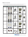
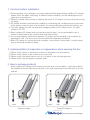
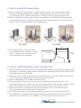
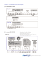
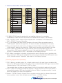
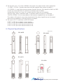
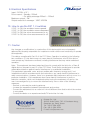
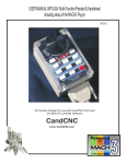
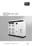
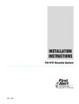
User’s Manual
Escalator Keeper
Escalator and Moving Walk Automatic Driving System
Escalator Passenger Protection, Control & Information System
ES-Keeper is a Trademark of Qccess Co., Ltd.
Made in Korea
http://www.qccess.com/es-keeper
What’s in the box?
1) Please check whether it matches with the model that you ordered and if there is anything left out.
2) In the Box: ES-Keeper main and sub post, bases for each post, bolts, nuts, keys, etc.
Model Name
Main Post, Sub Post
Base
Bolts, Nuts, etc
Keys
ES-100RE
ES-100HE
ES-100CY
ES-15RO
Escalator Keeper
http://www.qccess.com/es-keeper
1. Cautions before Installation
1) As the operation of an escalator or moving walk should be stopped when installing ES-Keeper,
please inform the public sufficiently in advance before installing it so that passengers do not
experience inconvenience.
2) Please be careful when moving or installing the posts of ES-Keeper not to be injured since they
are heavy.
3) ES-Keeper should be harmoniously installed by considering site conditions such as structures
at the entrance and exit area of an escalator (or moving walk) and architectural finishing, etc.
4) The input voltage must be checked when supplying power to ES-Keeper posts. The input
voltage is DC 24V.
5) When installing ES-Keeper main and sub post and its base, it is recommended to use a
leveler to adjust them to be a vertical and horizontal position.
6) It is recommended to install fence between ES-Keeper and the handrail of an escalator for
passengers’ safe. The fence is an item that should be separately purchased.
7) When ES-Keeper is connected with an escalator or an inverter control panel, it must be done
by a professional escalator installer.
2. Implementation of inspection on appearance when opening the box
1)
2)
3)
4)
Please
Please
Please
Please
check
check
check
check
if
if
if
if
there is any obvious scratch on appearance of the products.
there is any scratch on the main acryl.
the photo sensor acryl is in its place on the left and right side.
the pictogram is properly done.
3. How to arrange products
When installing ES-Keeper at the entrance and exit area of an escalator, a main post should
be installed on the left side and a sub post on the right side based on the direction of access
and exit.
main
sub
Single Escalator
main
sub
main
Parallel Escalators
Escalator Keeper
http://www.qccess.com/es-keeper
4. How to install ES-Keeper Base
1) When installing ES-Keeper base, it must be firmly fixed on the ground while looking
forward (or backward) direction carefully. Please note that the front and rear looks
of -Kthe base of ES-100RE model and ES-100HE model are opposite each other.
2) When installing ES-Keeper base, it must be installed on a flat ground. Besides, based
on the bottom surface, it must be constructed to be buried exactly up to the buried line
(50mm from the lowest bottom) of ES-Keeper base.
[unit: mm]
ES-100RE
ES-100HE
1.5 M
3) ES-Keeper base is recommended
to be installed at the distance of more
than 1.5 meters from the return part
of the handrail of an escalator.
Escalator
5. How to install ES-Keeper main and sub posts
1) Slide the rubber pad at the bottom part downward by standing ES-Keeper post upside down.
At this time, if necessary, apply lubricant between the rubber pad and the post body so that
the rubber pad can be slid easily.
2) Detach the outer clamps at both sides by loosening bolts of the outer clamps at the bottom
of ES-Keeper post. Subsequently, loosen internal bolts as well.
3) Open the back side of ES-Keeper post with the key.
4) After mounting ES-Keepr post to be proper for forward (or backward) direction, fix it
by using bolts and nuts. At this time, space is well secured so that the outer clamps on both
sides can be attached, and ES-Keeper post should be fixed to be exactly vertical.
5) The line connection is prepared in the future by pulling out the connection line from
ES-Keeper base into the inside of ES-Keeper post.
6) Re-attach the clamps on both sides by tightening screws, then the post will be fixed.
7) The installation is completed by sliding the rubber pad downward. (For more information,
please refer to a video clip on our website or a CD enclosed in the product box.)
Escalator Keeper
http://www.qccess.com/es-keeper
6 How to connect wires for ES-Keeper
1) In case of ES-100RE
2) In case of ES-100HE
Main Post
-
Operating Condition Display
Safety Message Speaker
Warning Buzzer against Reverse Approach
Passenger detecting Sensor
Escalator Keeper
http://www.qccess.com/es-keeper
7 How to check the wire connection
PIN
1
2
3
4
5
6
7
8
9
21CAP
10
DC3
11
12
13
14
15
16
17
18
19
20
21
UP MAIN
P24
GND
UP
DN
FAULT
INS
FIRE
AUTO
BUZZER+
BUZZER GND
PHOTO
SIGNAL
SENSOR
P24
PIN
1
2
3
4
5
13CAP 6
7
DC2
8
9
10
11
12
13
UP SUB
P24
GND
UP
DN
FAULT
INS
FIRE
AUTO
PIN
1
2
3
4
5
6
7
8
21CAP 9
10
DC4
11
12
13
14
15
16
17
18
19
20
21
DOWN MAIN
P24
GND
UP
DN
FAULT
INS
FIRE
AUTO
BUZZER+
BUZZER GND
PHOTO
SIGNAL SENSOR
P24
PIN DOWN SUB
1 P24
2 GND
3 UP
4 DN
5 FAULT
13CAP 6 INS
DC5
7 FIRE
8 AUTO
9
10
11
12
13
1) UP MAIN, UP SUB mean the posts which are installed at the top of an escalator.
DOWN MAIN, DOWN SUB mean the posts to be installed at the bottom of an escalator.
2) P24 = DC24V(+) Power. Power must be supplied from an escalator to ES-Keeper post.
GND = DC24V(-) Common Grounding
3) UP = It is a signal to be sent from an escalator to the post. When an escalator goes up,
if GND signal is added to this signal line, UP arrow is scrolled and displayed on the post.
4) DN = It is a signal to be sent from an escalator to the post. When an escalator goes down,
if GND signal is added to this signal line, DOWN arrow is scrolled and indicated on the post.
5) FAULT= When an escalator fails, a signal must be sent from the escalator to the post.
Upon a failure, GND signal is added to the post. If the post identified that GND signal is sent
to FAULT, it shows a text of ‘FAULT’ and a mark of ‘No Entering’ by turns.
6) INS = When an escalator is checked, a signal must be sent to the post from an escalator side.
When checking it, GND signal is added to the post. If the post identified that GND signal is sent
to INS, it shows a text of ‘Inspection’ and a mark of ‘No Entering’ by turns.
[Checking Signal Line Operation]
1) FIRE = When an escalator gets a fire, a signal must be sent to the post from an escalator side.
Upon a fire, GND signal is added to the post. If the post identified that GND signal is sent to FIRE,
it shows a text of ‘a fire’ and a mark of ‘FIRE’ by turns.
If an escalator does not have an output signal of a fire, this function is made not to be used.
2) AUTO = When an escalator automatically operates, a signal must be sent to the post. When it
automatically operates, GND signal is added to the post. When it operates manually, it would
work if any signal is not sent to this signal line.
3) Buzzer+ = DC24V+ Polarity. A signal from an escalator must be given to a buzzer that sounds
when a problem occurs at an escalator as well. Buzzer- = DC24V- Polarity
Escalator Keeper
http://www.qccess.com/es-keeper
4) The function of 11,12,13 pin of MAIN is the power of a photo sensor and a signal line.
11= GND = DC24V- [Sense power that must be supplied from power escalator-]
12= SIGNAL= In case that a person passes through the post, this signal line falls into GND.
It must go to the detection of a person accessing to an escalator.
It stops when there is no user for a certain period of time on an escalator.
After the stop, when it operates again, it operates while this sensor is detected.
13=P24+=DC24V+ [It is a sense power+ that must be supplied from an escalator.]
The output of the post is one sense signal and all the other signal lines are the signal
that must be supplied to multi post from an escalator.
5) The use of DIP 1,2 switches on MP1000 board
If DIP 1 is ON, the escalator moves upward.
If DIP 1 is Off, the escalator moves downward.
If DIP 2 is ON, the voice announcement is on.
If DIP 2 is Off, the voice announcement is off.
8. Physical Specifications
[unit: mm]
RE-100RE
RE-100HE
ES-100CY
ES-15RO
Escalator Keeper
http://www.qccess.com/es-keeper
Escalator Keeper
9. Electrical Specifications
Input : DC24V ±10%
Drive current : Standby 200mA
: On safety message 250mA ~ 300mA
Maximum output : 5W
Output method of message : 16BIT ADPCM
10. How to use the DIP 1, 2 switches
If
If
If
If
DIP
DIP
DIP
DIP
1
1
2
2
is
is
is
is
ON, the escalator moves upward.
Off, the escalator moves downward.
ON, the voice announcement is on.
Off, the voice announcement is off.
11. Caution
Any changes or modifications in construction of this device which are not expressly
approved by the party responsible for compliance could void the user's authority to operate
the equipment.
This device complies with Part 15 of the FCC Rules. Operation is subject to the following
two conditions: (1) this device may not cause harmful interference, and (2) this device
must accept any interference received, including interference that may cause undesired
operation.
Note : This equipment has been tested and found to comply with the limits for a Class B
digital device, pursuant to part 15 of the FCC Rules. These limits are designed to provide
reasonable protection against harmful interference in a residential installation.
This equipment generates, uses, and can radiate radio frequency energy and, if not
installed and used in accordance with the instructions, any cause harmful interference to
radio communications. However, there is no guarantee that interference will not occur in a
particular installation. If this equipment does cause harmful interference to radio or
television reception, which can be determined by turning the equipment off and on, the
user is encouraged to try to correct the interference by one or more of the following
measures:
- Reorient or relocate the receiving antenna.
- Increase the separation between the equipment and receiver.
- Connect the equipment into an outlet on a circuit different from that to which the receiver
is connected.
- Consult the dealer or an experienced radio/TV technician for help.
INNOVATIVE TECHNOLOGY
FOR HUMAN LIFE
www.qccess.com/es-keeper
Qccess Co., Ltd.
#1818, Anam Tower, 702-10 Yeoksam-dong,
Gangnam-gu, Seoul, Korea
Tel : +82-2-564-4782
Fax: +82-2-564-4784
E-mail: [email protected]