1
OPENCOCKPITS IOCards USBSERVOS
INSTALLATION AND USERS MANUAL
INSTALLATION AND USER’S MANUAL v1.0
IOCards USBSERVOS
INTRODUCTION
The Opencockpits USBServos card is designed to handle up to 6 servo motors, similar to the type used in
Radio Controlled Aircraft. The Card also provides four analog inputs, to cater for Potentiometers.
The USBServos Card connects to a computer via a USB port. Upon connection, the device is instantly recognized
as a HID device. The card is interfaced to FS2004/FSX via SIOC and the IOCP Server, available free of charge from
Opencockpits' website.
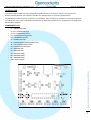
COMPONENTS LIST
C1 = CAPACITOR 220nF
C2, C3 = CAPACITORS 22pF
C4, C5 = CAPACITORS 100nF
D1 = LED (Light Emitting Diode)
IC1 = MICROCHIP 16C745
J1 = CONNECTOR USB
J2 = POWER SOURCE CONNECTOR 2 PINS
J3… J14 = CONNECTORES 3 PINS
Q1 = QUARTZ CRYSTAL 6MHz
R1 = RESISTOR 1K5
R2 = RESISTOR 10K
R3 = RESISTOR 100R
R4 = RESISTOR 470R
R5 = RESISTOR 470R
SW1 = RESET 2 PINS
INSTALLATION AND USER’S MANUAL IOCards USBSERVOS
-
2
INSTALLATION AND USER’S MANUAL v1.0
IOCards USBSERVOS
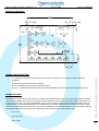
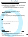
PRINCIPAL MEASURES:
•
J1 = This square connector provides the connection to a computer via a USB port, using a USB cable
(supplied).
•
•
•
J2 = Servo Power Source connector +5Volts.
J3 to J6 = Analog input connectors (Potentiometers).
J9 to J14 = Three Pin Servo Connectors (5V, DATA, GROUND). See information below regarding wiring.
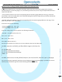
WIRING DIAGRAM:
The wiring of components for this card is very simple. For Potentiometers, three sets of three pins (Wiper, Ground
and 5V) are accessible (Pins J3 to J6). To connect a Servo Motor to the card, pins J9 to J14 must be used. These sets
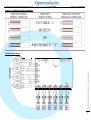
of pins have three pins, 5V, DATA and GROUND. As most Servo manufacturers do not tend to standardize their pin
configurations, you will most likely have to re-arrange the servo motor leads so that they match the format of this
interfacing card. Please ensure that your servo lead is configured as per the following text, and also please study the
subsequent table to see a visual model of adjusting certain manufacturers' leads (Futaba, etc).
• Pin1 = +5V
•
Pin2 = Data (S)
•
Pin3 = GND
INSTALLATION AND USER’S MANUAL IOCards USBSERVOS
CONNECTORS DESCRIPTION:
3
INSTALLATION AND USER’S MANUAL v1.0
IOCards USBSERVOS
TABLE OF CONNECTIONS BY BRAND:
INSTALLATION AND USER’S MANUAL IOCards USBSERVOS
WIRING DIAGRAM:
4
INSTALLATION AND USER’S MANUAL v1.0
IOCards USBSERVOS
Please note, the USBServos card must be fed externally with a +5V Power Source. This is because the USB output from
The computer alone is not enough to provide the servo motors with power on its own. To connect a 5V power source,
use the dual-pin J2 connector on the card (see diagram). It is VERY important that the positive and negative terminals
are connected the correct way round (these terminals are labelled respectively on the card).
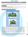
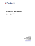
TESTING SOFTWARE:
To test the functionality of the card, and to confirm that the card has been correctly set up, run the IOCards testing
program (please click the blue hyperlink to download).
Using this application, we can check the movement of the servo motor(s) according to our inputs, and record certain
“step” values – A great help when interfacing the card using SIOC (see later).
In the above diagram, several important pieces of information can be seen. Firstly, circled with the Red ellipse,
the “step” value of a specific servo motor can be entered and recorded for reference. In this field, any number
between 0 and 1023 can be entered; with 0 being minimum deflection of the servo motor, and 1023 being
maximum deflection. The Blue circle is highlighting the Servo Selection Bullet. This bullet simply controls which
servo is the current “active” servo. For example, in the above diagram, Servo 1 is currently being adjusted, as
there is a bullet in the Servo 1 field. A servo cannot be adjusted unless there is a bullet present in its respective
Field. Finally, in the Magenta ellipse, we can see the fine adjustment tool. This sliding arrow has an identical
Purpose to the Red ellipse (being that it controls the servo's position), however it allows the user to make much
more precise adjustments. The slider can be moved either with a mouse, or using the left and right arrow keys
on your keyboard.
Visible to the right of the application, the Device window can be seen. This window simply tells us the four digit
device number of the USBServos card we are currently using. If more than one USBServos card is connected, the
Device window will turn into a drop-down menu, allowing us to select between the two (or more) cards
connected to the PC. Each card has its own, unique device number.
INSTALLATION AND USER’S MANUAL IOCards USBSERVOS
When the application is executed, the following window appears:
5
INSTALLATION AND USER’S MANUAL v1.0
IOCards USBSERVOS
USING SIOC:
Please ensure you are using version 3.46 of SIOC or higher. If not, please download using the following link:
http://www.opencockpits.com/catalog/info/information.php?info_id=31&cPath=2
Once SIOC has been successfully installed, we can begin the process of setting up the USBServos Card.
The first step is to configure the SIOC.ini file.
SIOC.ini is a small but very essential file provided with every correct installation of the free ware SIOC
Software. It is the initialization file that SIOC reads every time it starts up. Think of it as “the brain” behind
SIOC – Whatever the SIOC.ini file says, SIOC carries that task out.
Basically, one must add the line [USBSERVOS=N,X], where N is the “index” number of the USBServos Card
(ie how many you have in your system. Card number one = 0, Card number two = 1, and so on).
Next, below that line, the user must add the following instruction [deviceUSB=M], where M is the device
number of the USBServos Card. To find the device number, one can look in the main SIOC window, found
after starting SIOC.exe. Please see the following for the example of a suitable SIOC.ini file:
//
[SIOC]
IOCP_port=8092
IOCP_timeout=4000
Minimized=Yes
toggle_delay=20
CONFIG_FILE=ServoVSI.ssi
[DEVICE INFORMATION]
USBSERVOS=0,77
deviceUSB=2132
[FSUIPC MODULE]
FSUipcdisable=No
FSUipcRefresh=50
[IOCP CLIENTS MODULES]
IOCPini_delay=3000
IOCPclient0_disable=Yes
IOCPclient0_host=localhost
IOCPclient0_port=8090
IOCPclient1_disable=Yes
IOCPclient1_host=localhost
IOCPclient1_port=8099
[SOUND MODULE]
Sound_disable=Yes
Volume=100
//
Please note that the values of 0,77 and 2132 must be substituted depending on your PC.
Also note the line [CONFIG_FILE=ServoVSI.ssi]. This is where we tell SIOC.ini what our SIOC script is, and
where it is located (the SIOC file should be always located in the main SIOC Folder directory).
INSTALLATION AND USER’S MANUAL IOCards USBSERVOS
[IOCARDS MODULE]
IOCard_disable=No
IOCard_LPT=No
6
INSTALLATION AND USER’S MANUAL v1.0
IOCards USBSERVOS
ANALOG INPUTS IN SIOC (Only read if using a potentiometer with the Card):
To use the analog potentiometer inputs on the card, please use the following SIOC script example:
Var VVVV, name NNNNNNNNNNNN, Link USB_ANALOGIC, Device DD, Input# EE, posL LLL, posC CCC, posR RRR
•
•
EE = Analog input number; any number between 1-5 (DEPENDS on which input the potentiometer is connected
to. For example, if using the J3 connector pin, EE = 1.
LLL = The maximum left-hand position of the Potentiometer. These values can be found using the
aforementioned IOCards testing application.
• CCC = The central position value of the potentiometer. Again, please use the IOCards testing utility for reference.
•
RRR = The maximum right-hand value of the Potentiometer. Once again, use the IOCards testing program.
.
NNN = This represents a name. This entry is optional. The name can be anything you want, (such as the
example below, “pot flaps”). Spaces are represented by an underscore (_).
ANALOG SIOC DEFINITION EXAMPLE:
Var 1506, name pot_flaps, Link USB_ANALOGIC, Device 1, Input# 2, posL 1, posC 128, posR 255
SIOC SCRIPTING EXAMPLE:
The following SIOC script example involves getting a simple airspeed indicator (ASI) gauge to work. The gauge is
linear, and thus does not require any overly complex calculations; just basic servo-scaling work. The following is
intended as an example only of how to get a simple gauge working with the USBServos Card.
Please note, FSUIPC (unregistered) is required to use SIOC.
Script:
Var 9003, name IAS, Link FSUIPC_IN, Offset $02BC, Length 4 // IAS from Sim
{
L0 = DIV &IAS 128
L1 = L0 * 1.91 // Calculate Servo Slope
L2 = L1 + 271.5 // Calculate Servo Intercept
V9000 = L2
}
Var 9000, name Servo3, Link USB_SERVOS, Output 3, PosL 271, PosC 606, PosR 940, Type 2 // ASI
gauge
//
Things to note:
- “Link FSUIPC_IN, Offset $02BC” - This is the FSUIPC Offset entry for Indicated Airspeed (IAS). “Length 4”
means that the Offset has a length of 4 bytes.
- (From “L0 =” to “L2 =”) This is the calculation required to convert the FSUIPC Offset into a workable value
for SIOC. This also provides the correct “Servo Scaling” for a servo motor, which, of course, must be
changed according to the values of your own motor (no two motors are the same). These calculations are
discussed below, on the next page.
After this calculation, the Boolean Integer “L2” will hold the “servo signal” data for the FSX IAS Knots Value.
INSTALLATION AND USER’S MANUAL IOCards USBSERVOS
//
7
INSTALLATION AND USER’S MANUAL v1.0
IOCards USBSERVOS
(Advanced extra reading) SCALING CALCULATIONS FOR LINEAR GAUGES:
Using a fairly simple formula, it is possible to develop a SIOC script that controls linear gauges (such as Boeing
Airspeed Indicators, certain EGT gauges, etc). The following assumes that you are using an airspeed indicator with a
range of 50-350 Knots.
- Firstly, find the minimum servo value corresponding with the minimum gauge deflection value (eg, if “50 Knots”
on your ASI is “210” servo value (these can be obtained through the IOCards testing utility as previously mentioned)
then write these numbers down).
- Secondly, obtain the maximum servo value corresponding with the maximum gauge deflection value (eg, if “350
Knots” on your ASI is “735” servo value).
From this we can learn the following:
- The Servo Range is 735 – 210 = 525
- The Gauge Range is 350 – 50 = 300
To get our scaling values, we must perform the following calculations:
- 525/300 = 1.75 (We'll call this value “A”)
210 = (1.75 * 50) + 122.5
897 = (1.75 * 350) + 122.5
122.5 (We'll call this value “B”).
Var 9003, name IAS, Link FSUIPC_IN, Offset $02BC, Length 4 // IAS from Sim
{
L0 = DIV &IAS 128
L1 = L0 * A // Calculate Servo Slope
L2 = L1 + B // Calculate Servo Intercept
V9000 = L2
}
Var 9000, name Servo3, Link USB_SERVOS, Output 3, PosL 210, PosC 525, PosR 735, Type 2 // ASI gauge
You can use the above equation(s) whenever you are designing a linear instrument/gauge. It provides an accurate
and fairly easy calculation to get servo motors working quickly and effectively.
INSTALLATION AND USER’S MANUAL IOCards USBSERVOS
Now that we have both of our values, we can now substitute them into the SIOC script:
8
INSTALLATION AND USER’S MANUAL v1.0
IOCards USBSERVOS
Note:
Software programs, circuits and content published in this paper and on our website are copyrighted by their
developers, who doesn't consent to their use for commercial gain, unless authorized in writing.
The software and content published and any code developed can be distributed as often as necessary and through
desired media without written authorization, provided that the publication is acknowledged to the author and the
source from which comes.
INSTALLATION AND USER’S MANUAL IOCards USBSERVOS
www.opencockpits.com
8