1
OPENCOCKPITS IOCards USBExpansion + Master INSTALLATION AND USER’S MANUAL INSTALLATION AND USER’S MANUAL v1.0 IOCards USBExpansion + Master INTRODUCTION Due to the changes on the last generation of computers and the disappearance of the parallel ports on the PCs, we can’t give more technical support to the Master cards connected via parallel port, so this guide is published only with the use of the Master joined to the USBExpansion . The USBExpansion was designed specifically to connect to the USB port and improve the ease of configuration of both cards. TARJETA MASTER COMPONENTS LIST: -
P1 = CONNECTOR DB25 MALE P2 = CONNECTOR DB9 MALE J0 = 2 PINS POWER SOURCE J1, J2, J3 Y J4 = CONNECTOR 40 PINS BT224 TYPE DIODE 1 …. DIODE 8 = 8 DIODES 1N4148 GROUPS (TOTAL OF 72) R1 … R9 = RESISTORS 6K8 0,33W IC1 = 74HC154N IC2 … IC9 = 74H259 IC10 = 74HC541 INSTALLATION AND USER’S MANUAL IOCards USBExpansion + Master 2 INSTALLATION AND USER’S MANUAL v1.0 IOCards USBExpansion + Master PRINCIPAL MEASURES: •
•
•
•
•
•
•
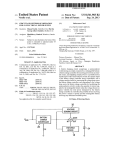
P1 = USBExpansion connector, this connector allows to connect to the PC (via USBExpansion) P2 = 7 auxiliary inputs connector. J0 = Power source connector, the Master card must be powered always with 5V. J1 = Bus for the DISPLAYS II cards, this allow connect up to 4 displays card, this is a total amount of 64 digits. J2 = Outputs connector, where you can connect and manage Leds. The pin1 is the positive, but usually never is used, due that the outputs are feeded from the power source. The pin2 is the GND, and is common for all the outputs. We can manage up to 38 outputs. (see image below) J3 = Inputs connector, we can connect switches, pushbuttons, etc., it have 4 groups of 9 inputs plus a GND, giving us a total of 36 inputs (see image below) J4 = As same the J3. INPUTS The inputs on the Master card are formed in groups of 9 + GND, this means that we have a total of 36 inputs on each input connector (J3 and J4), that is, for each Master card connected to the USBExpansion, we have 72 inputs, that multiplied by 4 cards on each USBExpansion, this means we have a total of 288 digital inputs, numbered as on the following table: Master card number 1 2 3 4 J3 inputs 0 – 35 72 – 107 144 – 179 216 – 251 J4 inputs 36 – 71 108 – 143 180 – 215 252 – 287 INSTALLATION AND USER’S MANUAL IOCards USBExpansion + Master CONNECTORS DESCRIPTION: 3 INSTALLATION AND USER’S MANUAL v1.0 IOCards USBExpansion + Master The virtual/logical inputs doesn’t correspond to the physical pin number, the, the input number 0 doesn’t correspond with the pin number 1, the input number 1 doesn’t correspond with the pin 2, etc… The distribution of virtual numerical of the Master is as follows, where we can see only the J3 connector, but the logics are the same, only varies on the numbers, as an example on the J4, the pin 1 is the logical input number 36, the pin 2 is the 37, etc.: Here we can see the several groups, up to for on each connector and in every one we have a GND and it is NOT interchangeable, that means that the inputs on each group must use their own GND, not from another group. On the following image we can see an example of the wiring of several elements on the Master. In it we can see clearly the switches connected to the pins 2 and 3, and also some pushbuttons on the pins 1 and 31, and finally an encoder connected to the pins 32 and 34 (that correspond to the logical inputs number 29 and 30), this is in this way due that the encoders must be connected on two consecutive logical inputs. As we also see here, the GND in all cases always is from the same group where we connect the several devices. OUTPUTS Each Master cards have up to 45 outputs in the two connector J2 and P2 (38 and 7 outputs respectively), this is a total of, for the 4 Masters connected to the USBExpansion, 180 outputs and the numbering as showed on the following table: Master card number 1 2 3 4 J2 11 – 48 75 – 112 139 – 176 203 – 240 P2 49 – 55 113 – 119 177 – 183 241 – 247 INSTALLATION AND USER’S MANUAL IOCards USBExpansion + Master 4 INSTALLATION AND USER’S MANUAL v1.0 IOCards USBExpansion + Master The outputs give us 5V on each, in it we can connect usually leds, because the amperage that the outputs gives us is really low, almost 25 mA on each outputs and we can’t connect devices with an high consumption. The wiring of those leds are as show on the following diagram: Due the voltage needed to power the own led, we must use a resistor between the positive and the own led. For the calculation of the value for this resistor, you can found on Internet some free application to calculate this, so, if you want to calculate it, there is the formula: Where: Vs = Power source voltage Vf= LED voltage If = LED Intensity (amperage) As an example, we have the output that gives us 5V, a led that uses 2,2V with an amperage of 20mA (0.02A), and the calculation are: R = (5 – 2.2)/0.02 = 140 ohmios Conclusion, we need to use a resistor of 150 ohm, because this is the lower standar resistor near to 140 ohm. WE must also note the position of the LED, because it has a “positive” (cathode) and “negative” (anode). This, on the LED can be easily distinguished because they have two characteristics, the legs of the leds are different, the cathode is shorter than the anode and also inside the plastic you can see the extension of the leg to the anode side. DISPLAYS Each Master card accepts in their displays bus up to four Displays II cards. INSTALLATION AND USER’S MANUAL IOCards USBExpansion + Master R = (Vs – Vf)/ If 5 INSTALLATION AND USER’S MANUAL v1.0 IOCards USBExpansion + Master The connector of this bus is the J1 connector and for the configuration of the cards we must use the own jumpers on the Displays card. For a better configuration and use of this card, please see the “Installation and user’s Manual for Displays II card”, also available for download on our web. INSTALLATION AND USER’S MANUAL IOCards USBExpansion + Master 6 INSTALLATION AND USER’S MANUAL v1.0 IOCards USBExpansion + Master USBEXPANSION CARD COMPONENTS LIST: -
J1, J2, J3 Y J4 = CONNECTORS DB25 FEMALE SW1, J7, J8, J9 Y J10 = 3 PINS MALE D1 = RED LED J6 = CONNECTOR FEMALE USB J5 = 2 PINS CONNECTOR FOR POWER SOURCE C1 = CERAMIC CAPACITOR 220nF C2 Y C3 = CERAMIC CAPACITOR 22pF C4 … HASTA C13 = CAPACITOR 0,1mF Q1 = QUARTZ CRYSTAL 6 MHZ R1 = RESISTOR 100R R2 = RESISTOR 10K R3 = RESISTOR 1K5 R4 = RESISTOR 470R IC1, IC2, IC3, IC4, IC8, IC9, IC10, IC11 = 74HC541 IC5 = 74HC253 IC6 = 74HC139 IC7 = 16C745 INSTALLATION AND USER’S MANUAL IOCards USBExpansion + Master 7 INSTALLATION AND USER’S MANUAL v1.0 IOCards USBExpansion + Master PRINCIPAL MEASURES: CONNECTORS DESCRIPTION: •
•
•
•
•
J6 = usb connector to PC J1, J2, J3, J4 = Master connector, with the connection order for it the same order as the connectors. J7, J8, J9, J10 = Analogic inputs, we can connect potentiometers J5 = Connector for power source, although it isn’t necessary to feed the USBExpansion, the connector is supplied to the case where the computer itself via the USB couldn’t provide enough power for the electronic components of the own card. SW1 = Reset of microchip (not used usually) INSTALLATION AND USER’S MANUAL IOCards USBExpansion + Master 8 INSTALLATION AND USER’S MANUAL v1.0 IOCards USBExpansion + Master PUESTA EN MARCHA DE LAS TARJETAS WIRING THE USBExpansion AND THE Master This should ideally connect elements to outputs and inputs for better testing of different devices. The connections of these elements we have them described in this manual in the relevant sections (OUTPUTS, INPUTS, DISPLAYS). There is also an option to connect the inputs and outputs, which greatly facilitates us the work of wiring, that option is to use the easy connection option cards, which are references [3T5] Inputs and [3T4] Outputs from our catalog (see images). Once we have our different devices connected, we configure the controlador.ini file to detect our cards and in this way we can test it with the application controlador.exe INSTALLATION AND USER’S MANUAL IOCards USBExpansion + Master We must connect the cards as shown in the picture above, taking note that we ONLY feed the Master card NOT the USBExpansion, as discussed earlier in this manual and proceed to configure for testing purposes. 9 INSTALLATION AND USER’S MANUAL v1.0 IOCards USBExpansion + Master CONTROLADOR.INI FILE CONFIGURATION Below are the most important lines into this file, explaining the changes that we make in it, in order that the PC detects the cards an then we can test the performance of the cards. [ Uso de Expansión USB ] [ Iocard Master expansion USB ] USB=yes With this parameter indicate that we are using the USBExpansion card, therefore we shall always be activated with “yes” [ Múltiples USBs ] [ Non unique USB ] MUSB=No We will active with “yes” if the PC on which we are connected the USBExpansion+Master, we have other USB cards also connected (USBServos, USBLCD, etc…) [ Número de A/D a usar de la placa de Expansión USB ] [ A/D used by Iocard Master expansion USB ] USB_AD=4 In this parameter we activate analogic inputs as we want to use and test into the USBExpansion. This line tells to the program controlador how many cards Master we have connected to the USBExpansion, where we know already in what order we must connect. If we don’t provide it this information, the cards would work not properly. Once we have done the modifications, we can save and close this ini file on the same folder that we have installed the SIOC suite. CARDS TEST Now, we can proceed to run the controlador.exe application, by double‐click over the icon. This will display the next screen, where we have all components connected to the cards. Anyway we think that this program is strictly to test the cards, doesn’t serve us a program of communication with the simulator, as we will use, as we will see, our own programming language called SIOC. On the main screen of the controlador, we can see en their bottom right part a button with the legend “start”, click over it should activate the cards and now we have access to its elements: INSTALLATION AND USER’S MANUAL IOCards USBExpansion + Master [ Numero de tarjetas Master inter‐conectadas ] [ Number of connected master cards ] NCards=1 10
IOCards USBExpansion + Master As an example, if we need to test if an input works, on which we have connected a switch, simply we toggle this switch and on the “Inputs :” little field on their right side, we can see the cipher that identifies the last input activated. At the bottom of this we have a big white window where shows all activated inputs. For the outputs, we would use the box IN/DPLAY, which would put the output to activate and would click ON and OFF buttons to connect and disconnect the output, however if we are to "identify" a way out, would click on +ON and ‐ON , thereby making each click on these buttons would activate sequentially ordered outputs. In the case of a 7 segment display, we would display the number in the box IN/DPLAY and the number to represent in the "Digit (0‐9)” field, would click on OK and the selected digit number we would we've indicated that they represent. For analog inputs (potentiometers), in "A/D[x] =” field (x represents the number of analog input), we show the movement and consequently, the values that make these inputs from their pots. INSTALLATION AND USER’S MANUAL IOCards USBExpansion + Master INSTALLATION AND USER’S MANUAL v1.0 11
INSTALLATION AND USER’S MANUAL v1.0 IOCards USBExpansion + Master EJEMPLOS DE PROGRAMACION Switch + indicator (parking brake): Var 0001, Link FSUIPC_INOUT, Offset $0BC8, Length 2
// parking brake
Var 0002, Link IOCARD_SW, Input 10
{
IF V0002 = 1
{
V0001 = 32767
V0003 = 1
}
ELSE
{
V0001 = 0
V0003 = 0
}
}
Var 0003, Link IOCARD_OUT, Output 20
The only thing you must change in the script is marked in red, representing the numbers that identify the inputs and outputs in our assembly. As we can see the operation is very simple: ‐First you declare the variable $ 0BC8 FSUIPC, which is the variable that handles the parking brake, and is where we write the values that we send from our hardware. INSTALLATION AND USER’S MANUAL IOCards USBExpansion + Master ‐In the next line we can see that the switch to the "10" input (in our case), when is ON (value 1) sends to the offset V0001 the value 32,767 that is the value needed to activate the parking brake (this is why we consulted before the list of values in the FSUIPC offsets) and also sends an 1 to the V0003 (which is an output for the parking brake light), which makes light on the indicator. 12
‐If the value of the switch were any other, then the V0001 sends the value 0, which causes it to disconnect the parking brake, and the same value as the variable V0003 and so turns off the indicator. ‐The last line is the declaration of the output, which in our case is connected to the number 20 Encoder: Var 0001, Link FSUIPC_INOUT, Offset $07D4, Length 4
// VALOR ALTITUD EN EL PILOTO AUTO.
Var 0003, Link IOCARD_ENCODER, Input 2, Aceleration 6, Type 2
{
L0 = V0003 * 100
V0004 = LIMIT 0 ,50000 ,L0
}
Var 0004, Link IOCARD_DISPLAY, Digit 9, Numbers 5
{
V0001 = V0004 * 19975.37
}
IOCards USBExpansion + Master ‐The first line, as in the above case, is the declaration of the variable that represents the value of altitude on the autopilot, on it we read and write the value to make FS and hardware interact. ‐The second line declares the encoder, where we see clearly that it is "Type 2" which means it is connected directly to the Master in two consecutive inputs plus GND, as we saw earlier in this manual. ‐The operation is as follows, in a “internal" offset which is L0 (there are 3 internal variables L0, L1 and L2) we say that turning the encoder each step is multiplied by 100, then values would take the values in this way 100, 200, 300, 400, 500 etc ..., and if you turn in the opposite direction, then decrease the values, that is multiplied by ‐100. Also, if by any case, we connected the encoder "upside down" on that line then multiply by ‐100 which would change the direction of rotation of the encoder. ‐Then I say to write in the variable V0004 (which is subsequently declared as a display) the limited value using the LIMIT function between 0 and 50000 feet, and what you write as stated in L0 (each step * 100) ‐Finally we declare the display where we show that value, to tell him that every change of the display, the V0001 will send the value multiplied by a constant display (which in this case is the conversion from feet to meters, which is as FSUIPC ask to us) Note: Software programs, circuits and content published in this paper and on our website are copyrighted by their developers, who doesn't consent to their use for commercial gain, unless authorized in writing. The software and content published and any code developed can be distributed as often as necessary and through desired media without written authorization, provided that the publication is acknowledged to the author and the source from which comes www.opencockpits.com INSTALLATION AND USER’S MANUAL IOCards USBExpansion + Master INSTALLATION AND USER’S MANUAL v1.0 13