1
Date:04/16/12
Rev.:2.1
IOCard USB Servos Manual
IOCard USB Servos Manual
Index:
IOCARD USB SERVOS MANUAL ............................................................................................................... 1
INDEX:.......................................................................................................................................................... 2
INTRODUCTION: ......................................................................................................................................... 3
USB SERVOS: ............................................................................................................................................. 3
OUTLINE AND COMPONENTS: ................................................................................................................. 3
CONNECTOR’S DESCRIPTION: ...................................................................................................................... 3
CONNECTION SCHEME:................................................................................................................................ 3
STARTING THE CARD: ............................................................................................................................... 5
SOFTWARE INSTALLATION AND SETTINGS:.......................................................................................... 7
SERVO'S DECLARATION SCRIPT:................................................................................................................... 7
ANALOGIC INPUTS DECLARATION:................................................................................................................. 8
EXAMPLE SCRIPTS: ..................................................................................................................................... 8
Servos:.................................................................................................................................................. 8
Analogic inputs: .................................................................................................................................... 9
LINKS OF INTEREST: ................................................................................................................................. 9
www.opencockpits.com
2
IOCard USB Servos Manual
Introduction:
The USB Servos has been designed to manage up to 6 servos like the ones used in radio
control and also has 4 analogic inputs. The card is connected to the computer thru an USB port.
Usb Servos:
The computer recognizes and configures the card as a input device at the
moment of plugging. To manage the card we will use SIOC and integrated
IOCP protocol.
To use the card we have to declare it in sioc.ini, thus allowing the
management of 6 servos and 4 analogic inputs.
Outline and components:
- C1 = CAPACITOR 220 nf
- C2, C3 = CAPACITORS 22Pf
- C4, C5 = CAPACITORS 0,1uF
- D1 = LED DIODE
- IC1 = 16C745 MICROCONTROLLER
- J1 = USB CONNECTOR
- J2 = INPUT POWER FOR SERVOS 5V,
2 PINS (not protected for polarity
inversion)
- J3 … J14 = 3 PINS CONNECTORS
- Q1 = QUARTZ CRYSTAL 6Mhz
- R1 = RESISTOR 1K5
- R2 = RESISTOR 10K
- R3 = RESISTOR 100R
- R5 = RESISTOR 470R
- SW1 = RESET (2 PINS CONNECTOR)
Connector’s description:
• J1 = USB Connector, allows the connection directly to the computer by USB, at the moment of
connection the computer will recognize the card as an input device.
• J2 = Input power supply connector 5V for the servos.
• J3 a J6 = Analogic input connectors (see outline connections).
• J9 a J14 = Servo's connectors, the servo´s wires must be changed as shown in the referenced
table (see connection's table).
Connection scheme:
Connecting the card is very simple, to connect the potentiometers we use 3 pins connectors J3
to J6, if we see that the readings at the unused inputs fluctuate too much we can avoid it by
placing a jumper between pin 1 and 2 or pin 2 and 3 in each unused connector.
www.opencockpits.com
3
IOCard USB Servos Manual
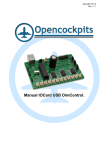
To connect the servos we have connectors J9 to J14, at these connections the wiring of the
servos connectors shall be changed (if needed) in order to adapt them to the IOCard USB pins,
depending on the brand of the servo, minding always the connecting order of servos to the card:
PIN
FUNCTION
1
+5v
2
DATA (S)
3
GND
For a better explanation of connections, see the image:
www.opencockpits.com
4
IOCard USB Servos Manual
Starting the card:
We already know how IOCard USB Servos works, so let's go test and connect it to see the
results.
In our example, we will connect the USB Servos card to an USB port and we will see that our
computer recognizes it.
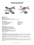
It has been recognized, so we will connect one 5V supply wire to J2 to feed the servos, 1
potentiometer to J3 and 1 HITEC servo to J9 (we will change the wiring order to red-yellowblack, +5V,S,GND), also to avoid false readings from unused analogic inputs we placed
jumpers on pins 1 and 2 on each connector:
www.opencockpits.com
5
IOCard USB Servos Manual
We will now test our assembly with SIOC Monitor, to see if all is well connected. We start SIOC,
looking for USB Servos being recognized and if positive, we will press the SIOC Monitor button
in IOCard USB Servos to check the card, servo and potentiometer.
As we can observe, the analogic input #1 shows the value of the potentiometer and the rest of
analogic inputs show 0, if we rotate the potentiometer we will see that the value changes from
more to less or vice versa (depending on the potentiometer wires connection), if we want to
reverse the turn direction we can do it two ways: changing pin 1 for pin 3 from J3 connector or
with a SIOC script.
www.opencockpits.com
6
IOCard USB Servos Manual
Let´s test the servo now, selecting the servo that we want to test, the servo will move
automatically to the indicated position in the ruler slide (0 to 1023 ticks), that means, Monitor
always starts in the middle of the ruler and the servo will go to his centre position. If we slide the
ruler pointer to the sides, the servo will turn to the sides.
Warning: we have noted that some servos have a little zone at the extremes where it is very
easy to rupture the physical turn limits, for example the Hitec HS55 (200º of turning more or less
from origin), if we put the ruler pointer under 190 in the scale from 0 to 1023 we will break the
servo's turn stop and it will turn crazy without limit (360º).
It is advisable to test all J connectors.
We can use this test to take note of values that take the pointers in the gauges, this being a big
help in order to program them in SIOC.
Important note about handling the servos:
When servos are connected to the USB Servos card and the card is powered by an external
supply, they must not be manually forced to run because gears will be broken and the motor
may burn. To manipulate the servos when connected to the USB Servos card we can order the
servos to go to position 0 and then it will possible to manipulate them manually. Manual
operation of servos being connected to the USB Servos card is not advisable because the
gears (if plastic built) can suffer irreversible damage.
Software Installation and settings:
If we want do the exercises explained in this manual for IOCard USB Servos, we must have
installed SIOC (newer version as possible), the flight simulator FS, FSX, X-Plane, etc., and we
will also need FSUIPC (registered).
At the end of this document there is a list of links to download the necessary software to put into
practice this manual.
To manage this card we use scripts, to control the IOCard USB Servos with SIOC we must edit
the sioc.ini to declare each connected card :
USBServos=XX,YY
XX index number (IDX) for each card.
YY device number in SIOC of USB port.
For example, if we connect two USB Servos cards with device numbers 2 and 42 (this numbers
are shown in SIOC upper right grey window) the cards declaration lines will be:
USBServos=0,2 (0 because it is the 1st, and 2 for USB device port 2,as our computer example).
USBServos=1,42 (1 because it is the 2nd, and 42 for USB device port 42).
Servo's declaration script:
To refer to the exact servo number, we must mind the index device number assigned to it in
each USB Servo card. The output code line will be declared as shown:
Var VVVV, name NNNN, Link USB_SERVOS, device DD, Output S, posL LLL, posC CCC,
posR RRR
VVVV = variable number.
NNNN = variable name (optional).
www.opencockpits.com
7
IOCard USB Servos Manual
DD = index number (IDX) declared in sioc.ini (if only have 1 card installed declared as 0: is not
necessary write device number).
S = servo number 1-6.
LLL = maximum left position of servo.
CCC = central position of servo.
RRR = maximum right position of servo.
Definition example:
Var 0001, name servo_vs, Link USB_SERVOS, Device 1, Output 5
Analogic inputs declaration:
To read the analogic inputs we will use the following code line format:
Var VVVV, name NNNN, Link USB_ANALOGIC, Device DD, Input EE, posL LLL, posC
CCC, posR RRR
VVVV = variable number.
NNNN = variable name (optional).
DD = index number (IDX) declared in sioc.ini (if only have 1 card installed declared as 0: is not
necessary write device number).
EE = analogic input number 1‐5.
LLL = maximum left position of device.
CCC = central position of device.
RRR = maximum right position of device.
Definition example:
Var 1506, name pot_flaps, Link USB_ANALOGIC, Device 01, Input 2, posL 1, posC 128, posR 255
Example scripts:
Servos:
We will build a vertical speed indicator varying from 2000 fpm UP to 2000 fpm DOWN, a total of
4000 fpm (feet per minute). We will connect the servo to the USB Servos card and we will feed
it. We will start SIOC Monitor as explained in the Starting the Card chapter, we will check the
servos limit positions (PosL, PosC and PosR, caring that in our example we are using a Hitec
servo and if we put a value under 190 we can break the servo).
The first thing to do is create a file named "pruebaservo1.txt":
// *****************************************************************************
// * Config_SIOC ver 4.01 - By Manolo Vélez - www.opencockpits.com
// *****************************************************************************
// * FileName : test_servo1.txt
// * Date : 15/03/2012
Var 0001, name servo, Link USB_SERVOS, Device 0, Output 1, PosL 190, PosC 512, PosR 1023
Var 0002, name vs_value, Link FSUIPC_INOUT, Offset $02C8, Length 4, Type 1
{
L0 = &vs_value * 0.7895
L1 = L0 * 0.2555 // 1022 positions / 4000 fpm
L2 = 511 - L1 // CENTER OF GAUGE
IF L2 > 1022 // UPPER LIMIT
{
L2 = 1022
}
www.opencockpits.com
8
IOCard USB Servos Manual
IF L2 < 1 // LOWER LIMIT
{
L2 = 1
}
&servo = L2
}
// End of file
We will write the script, save it and then run it with SIOC, we will start the simulator and choose
a light airplane (like Mooney), we will take off and see how the servo turns.
Analogic inputs:
Now, we will use the potentiometer connected to move the servo.
The first thing to do is create a file named "pruebaservo2.txt":
// *****************************************************************************
// * Config_SIOC ver 4.01 - By Manolo Vélez - www.opencockpits.com
// *****************************************************************************
// * FileName : test_servo2.txt
// * Date : 15/03/2012
Var 0001, name servo, Link USB_SERVOS, Device 0, Output 1, PosL 190, PosC 512, PosR 1023
Var 1506, name trim, Link USB_ANALOGIC, Device 0, Input# 1, posL 1, posC 128, posR 255
{
&servo = &trim
// End of file
We will write the script, will save it and will run it with SIOC, it is not necessary start the
simulator, if we turn the potentiometer the servo will turn too.
This ends this manual, we invite you to read the manuals of the others Opencockpits elements
and explore the SIOC software. We thank you for trusting us.
Links of interest:
Support area for clients:
http://www.opencockpits.com/catalog/info/
www.opencockpits.com
9