1
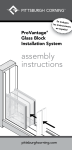
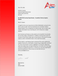
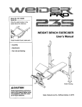
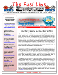
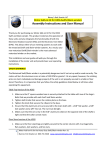
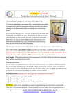
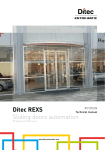
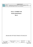
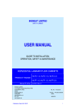
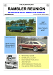
February 16th, 2015 Dr. Andrew Rawicz School of Engineering Science Simon Fraser University Burnaby, BC V5A 1S6 Re: ENSC 440 Functional Specification – Hermes: Camera Slider Motion Controller Dear Dr. Rawicz, Attached are the functional specifications for our camera slider solution Capstone project. The objective of this project is to produce a solution to add motorized controls to an existing camera movement device, which are user friendly and affordable. Our product would be used by video production companies to maximize productivity while at the same time minimizing cost. Various stages of development are covered in the functional specifications for the Hermes camera slider. Moreover, this document contains system overview, functionality constraints, overall product requirements, as well as sustainability and safety issues involved in our design. The founding partners of our company, Behnaz Edalat, Brendan Keane, Calvin Scott, Justin Raine and Martin Palibroda would like to personally thank you for your interest in our proposal. For any reason, feel free to contact us at [email protected]. Sincerely Yours, Behnaz Edalat, vitaMotu Ltd. vitaMotu Ltd. | [email protected] | i ENSC 305/440W Functional Specification February 16, 2015 Behnaz Edalat 301127510 Brendan Keane 301167176 Martin Palibroda 301179246 Justin Raine 301041695 Calvin Scott 301169228 vitaMotu Ltd. | [email protected] | ii Executive Summary In order to create the most cinematic shot for many kinds of movies, smooth motion is essential. However, in many cases this can become difficult or even impossible to achieve by hand, even with the use of a camera slider system. Motorized sliders provide the needed accuracy and precision to perform jitter-‐free motion and hours-‐long panning shots for time-‐ lapse and stop-‐motion videography. Unfortunately, currently available solutions are bulky and prohibitively expensive – often exceeding the cost of the camera. The group at vitaMotu has devised a solution, the Hermes, which motorizes a track system and, as a market differentiator, features remote control via a smartphone application. This opens up innovative pathways in creating a product that saves users money by using their existing smartphones as controllers, rather than expensive analogue solutions, while also removing the need to be wired that normal camera sliders feature. Along with the benefits that using a smartphone as a controller brings, the Hermes is also going to be easy to install to any camera slider rig, to allow for the widest market available. It follows that smaller film studios and independent filmmakers could use the Hermes to upgrade their equipment without having to replace the products that they already own and are accustomed to. At this stage in development, we are moving forward to reach the requirements set by the proof-‐of-‐concept designation. If time allows, we may attempt to completethe specifications determined for the prototype or even production level of the system. This document describes the functional specifications for the overall Hermes system, as well as details of the individual components. Several other topics will be covered, including the discussions and calculations used to determine the best hardware for the job, along with sustainability and safety considerations – and the standards to be met before a commercial release of our product. vitaMotu Ltd. | [email protected] | iii Table of Contents Letter of Transmittal ..................................................................................................................................... i Title Page ...................................................................................................................................................... ii Executive Summary .................................................................................................................................... iii Table of Contents ....................................................................................................................................... iv Table of Figures ........................................................................................................................................... v Glossary ....................................................................................................................................................... vi 1. Introduction .................................................................................................................................... 1 1.1 Scope ................................................................................................................................. 2 1.2 Intended User ..................................................................................................................... 2 2. System Overview ............................................................................................................................. 2 2.1 Usage .................................................................................................................................. 2 2.2 Top-‐Level Design ................................................................................................................ 2 2.3 Functionality Justification .................................................................................................. 4 2.4 Constraints ......................................................................................................................... 6 3. System Requirements ..................................................................................................................... 6 3.0.1 General Requirements ........................................................................................................... 6 3.0.2 Environmental Requirements ................................................................................................. 7 3.0.3 Safety Requirements .............................................................................................................. 7 3.0.4 Standards ................................................................................................................................ 7 3.1 Hardware Requirements .................................................................................................... 7 3.1.1Electrical Requirements .......................................................................................... 8 3.1.2Operation Requirements ......................................................................................... 8 3.1.3 Enclosure Requirements ........................................................................................ 8 3.2 Firmware Requirements .................................................................................................... 9 3.2.1 General Requirements ........................................................................................... 9 3.2.2 Setup Requirements ............................................................................................... 9 3.2.3 Network Requirements .......................................................................................... 9 vitaMotu Ltd. | [email protected] | iv 3.2 Software Requirements ................................................................................................... 10 3.2.1 General Requirements ......................................................................................... 10 3.2.2 Setup Requirements ............................................................................................. 10 3.2.3 Network Requirements ........................................................................................ 10 3.3 Documentation Requirements ........................................................................................ 11 4. Sustainability/Safety ...................................................................................................................... 12 5. Conclusion .................................................................................................................................... 13 6. References ..................................................................................................................................... 14 Table of Figures Figure 1 – Cinevate Hedron Camera Slider ................................................................................................... 1 Figure 2– High Level System Block Diagram ................................................................................................ 3 Figure 3– Mobile Application Block Diagram ............................................................................................... 3 Table 1 – Physical System Constraints ......................................................................................................... 4 Table 2 – Physical Motor Constrains ............................................................................................................ 4 vitaMotu Ltd. | [email protected] | v Glossary Term Definition Bluetooth Short range wireless communication standard Raspberry Pi Small and inexpensive single board computer Arduino Simple microcontroller family CPU Central Processing Unit LANC Local Application Control Bus System LED Light Emitting Diode CSA Canadian Standards Association FCC Federal Communications Commission ICES Industry Canada Electric Standards IEEE Institute of Electrical and Electronics Engineers App Short-‐hand form for mobile application ABS Acrylonitrile butadiene styrene PLA Polylactic Acid CNC A computer controlled fabricating machine Prosumer A market segment between professional and consumer GUI Graphical User Interface vitaMotu Ltd. | [email protected] | vi 1.0 Introduction The Hermes camera slider motion controller is an innovative solution to capturing smooth, quality time-‐ lapse and stop-‐motion recordings. Designed to be economical and functional, the Hermes is one of the only products of its kind to feature a mobile application based controller while still remaining cost competitive. Intended to be used by both professional filmmakers and independent videographers, the motorized motion control unit will be an add-‐on to compatible slider systems already existing on the market via different manufacturer specific mounting brackets. Pricing the unit below current competitors will maximize the size of the target market base to help negate this intrinsically niche market. Figure 1 shows the camera slider we will be using in our development process. Figure 1: Cinevate Hedron Slider System The Hermes requires a minimal learning curve, and aside from the installation of the motor and motor controller, is very easy to operate. With this in mind, the mobile app features an intuitive interface and a wealth of features. vitaMotu Ltd. | [email protected] | 1 1.1 Scope This document details the functional specifications for the motor, the motor controller, the control box, the wireless communications and the mobile app. Along with the sustainability and safety issues and engineering standards, these specifications will be used to drive the design process and develop the testing plan of the product. 1.2 Intended User The intended users range from professional filmmaker to independent videographers. The target demographic has a reasonable technical ability by nature of the market, however this will not be required for basic operation. Given the cost of the system, users are recommended to be at least 16 years old. Persons under this age who are entrusted with expensive cameras and the equipment can and should be trained to use the equipment by the owner. 2.0 System Overview 2.1 Usage User interaction with the Hermes motion control system is divided into two subsystems: the physical motor and motion controller, and the mobile app. Users must first attach the motion control system to a compatible slider system with the provided hardware adaptors. The physical motor and motion controller are designed for minimal user interaction, featuring only a battery connection, power on/off control, a Bluetooth pairing button, and status indication lights. The majority of user interaction and customization occurs in the mobile app environment. Users are prompted to pair their device upon first launch after which they have complete control of the system via a Bluetooth connection. Available controls include a live mode for manual operation of slider position, speed, and damping as well as time-‐lapse and stop-‐motion modes for pre-‐programmed slider movements. All positioning and camera start/stop controls are accomplished via the mobile application. 2.2 Top-‐Level Design The Hermes camera slider system consists of an Arduino microcontroller acting as the central processing unit. The CPU is connected to a power button, status lights for power and connectivity, a Bluetooth transmitter to communicate with mobile devices, motor control, feedback from an encoder via a Raspberry Pi, and a LANC transceiver. A high level block diagram of the system is depicted below in Figure 2. vitaMotu Ltd. | [email protected] | 2 Figure 2: High Level System Block Diagram The motion control system is controlled via a Bluetooth connected mobile device. The following system diagram shows the primary components of the mobile application. Figure 3: Mobile Application Block Diagram vitaMotu Ltd. | [email protected] | 3 2.3 Functionality Justification Market research was conducted to determine functionality specifications. Interviews were conducted with Cassiar MediaWorks, a local film production company, where questions were asked to determine the ideal specifications of a slider motion control system in field use. Specification Value Maximum camera payload 6.5 kg Minimum tracking speed 1 foot per hour = 5.13 mm/s Maximum tracking speed 1 foot per second = 0.3048 m/s Maximum slider angle 30 degrees Table 1: Physical System Constraints The following slider component specifications were measured or approximated from the Cinevate Hedron camera slider. Values for the slider efficiency and coefficient of friction were taken from a motor selection guide provided by a motor manufacturer [2]. Specification Value Motor gear diameter 5.08 cm Slave gear diameter 1.35 cm Motor and slave gear weight 100 g Belt weight 300 g Coefficient of friction 0.05 Efficiency 0.85 ~ 0.95 Table 2: Physical Motor Constraints vitaMotu Ltd. | [email protected] | 4 The minimum and maximum rpm were calculated from the specified tracking speed of the camera as follows, assuming a 2 inch diameter motor gear: Min: 1.0 !""# !! Max: 1.0 × !""# ! !".!" !" !""# × × !".!" !" !""# !"# !!!.!" !" × × !"# !!!.!" !! !! !" !"# × !" ! !"# = 0.0318 𝑟𝑝𝑚 = 115 𝑟𝑝𝑚 Assuming a stepper motor with 200 steps per revolution, this equals 0.106 steps/s and 383 steps/s, respectively. Motor torque requirements were calculated using a 2.0x safety factor as follows: 𝐽!"#$ = 1 𝑚 𝐷 𝐷 = (0.25)(6.5)(0.035)(0.05) = 0.2844×10!! 𝑘𝑔 ⋅ 𝑚 ! 4 ! ! ! 1 𝐽!"#$% = 2 ∙ 𝑚! 𝐷! 𝐷! = (2)(0.25)(0.1)(0.035)(0.05) = 8.750×10!! 𝑘𝑔 ⋅ 𝑚 ! 4 𝐽!"#$ = 1 𝑚 𝐷 𝐷 = (0.25)(0.3)(0.035)(0.05) = 1.313×10!! 𝑘𝑔 ⋅ 𝑚 ! 4 ! ! ! 𝐽!"#$% = 𝐽!"#$ + 𝐽!"#$% + 𝐽!"#$ = 3.063×10!! 𝑘𝑔 ⋅ 𝑚 ! 𝑇!""#$#%&'()* = 𝐽!"#$% 𝑇!"#$ = 𝜔! − 𝜔! = (0.003063)(24 − 0)/0.5 = 0.1470 𝑁 ⋅ 𝑚 𝑡 𝑚! 𝑔𝐷!"# (𝑠𝑖𝑛 𝛼 + 𝜇 𝑐𝑜𝑠 𝛼) (6.5)(9.8)(0.5)(𝑠𝑖𝑛 30° + 0.05 𝑐𝑜𝑠 30°) = = 10.18 𝑁 ⋅ 𝑚 2𝜂 2(0.85) 𝑇!"#"$ = 𝐾! (𝑇!""#$#%&'()* + 𝑇!"#$ ) = (2)(0.1470 + 10.18) = 20.65 𝑁 ⋅ 𝑚 Where, J: Moment of inertia (kg⋅m2) mL: Mass of load (kg) D: Diameter of gear (m) ω: Angular velocity (rad/s) t: Time (s) g: Force of gravity (m/s2) α: Angle of inclination (rad) μ: Coefficient of friction η: Efficiency Ks: Safety factor Additional functionality was established to conform to desired operations as specified by Cassiar MediaWorks (e.g. Bluetooth connectivity, operating time, market price), as well as safety and operation standards necessary for a marketed product. vitaMotu Ltd. | [email protected] | 5 2.4 Constraints The primary constraints of the system are total cost and weight. Given that our product is aimed at the relatively overpriced prosumer market, a lower price point than the commercially available camera slider models is our primary objective. The weight of the system is also a primary constraint due to the mobile nature of the product and the power of the motor available. Therefore the system must remain light and compact enough so as to preserve the mobility of the device. Additionally, the design of enclosure must be made for easy, non-‐destructive installation with the existing rail system. 3.0 System Requirements The following section will detail the requirements of the motion control system provided by vitaMotu. These requirements will be broken up into three main design components: -‐ -‐ -‐ Hardware: Electrical, Operational, and Enclosure Requirements Firmware: General, Setup, and Network Requirements Software: Application user will use for control of device. System requirements will be met at one of three different stages of development: proof-‐of-‐concept, prototype, and production versions. The following requirements include one of the following suffixes indicating the target stage for requirement compliance: -‐ -‐ -‐ PC: Requirement compliance to be met by proof-‐of-‐concept device PT: Requirement compliance to be met by prototype device PD: Requirement compliance to be met by production device The following section will be dedicated to describing specific requirements within each of these sections. However, a general overview has first been provided to give a higher level view of the product scope. vitaMotu Ltd. | [email protected] | 6 3.0.1 General Requirements [Req 3.0.1.1 -‐ PD] Retail price of the system should not exceed $1000 [Req 3.0.1.2 -‐ PT] System is designed to be splash resistant [Req 3.0.1.3 -‐ PD] System is designed to be dust resistant [Req 3.0.1.4 -‐ PT] System is designed to operate in 0⁰ C – 40⁰ C [Req 3.0.1.5 -‐ PT] System is designed to be stored in -‐40⁰ C to 60⁰ C [Req 3.0.1.6 -‐ PD] System should be easy to install and with minimal instruction [Req 3.0.1.7 -‐ PT] Basic functionality should be intuitive for the average user, while advanced function can be learned within 10 minutes [Req 3.0.1.8 -‐ PD] Product must be highly portable and less than 5 lbs 3.0.2 Environmental Requirements [Req 3.0.2.1 -‐ PT] The system is constructed for long term use so as to minimize waste [Req 3.0.2.2 -‐ PT] Highly recyclable aluminum enclosure [Req 3.0.2.3 -‐ PD] System free of lead based components 3.0.3 Safety Requirements [Req 3.0.3.1 -‐ PC] System designed so as not to damage the existing rail system [Req 3.0.3.2 -‐ PT] System must be stable within exposure temperatures during operation [Req 3.0.3.3 -‐ PD] Enclosure free of sharp corners for safe transportation [Req 3.0.3.4 -‐ PT] Hardware secured to prevent loose parts and shorts [Req 3.0.3.5 -‐ PD] Motor safely isolated from user to prevent injury 3.0.4Standards [Req 3.0.4.1 -‐ PD] System meets all Canadian Standards Association (CSA) electrical standards [3] [Req 3.0.4.2 -‐ PC] System meets Federal Communication Commission (FCC) Wireless regulations [4] [Req 3.0.4.3 -‐ PT] System complies with Industry Canada Electric Standards (ICES) [3] [Req 3.0.4.4 -‐ PT] System complies with IEEE Standards [5] vitaMotu Ltd. | [email protected] | 7 3.1 Hardware Requirements The below section is dedicated to the hardware requirements of the system. These requirements will be divided into the electrical, operational, and enclosure requirements. Given the time constraints, preference will be given to attributes of the device that will allow for the creation of a functional prototype. Such preferences include the likely foregoing of a complete PCB circuit which would be used in production for a functional breadboard model, and a less aesthetically pleasing enclosure. Therefore the main objective for the prototype is to provide an inexpensive motorized extension for existing camera slider models, competitive with existing products in functionality. 3.1.1 Electrical Requirements [Req 3.1.1.1 -‐ PC] Circuitry will be powered by a 12 VDC battery pack [Req 3.1.1.2 -‐ PC] The system battery will be charged by standard 110V -‐ 230V 60Hz AC [Req 3.1.1.3 -‐ PC] LED to distinctly communicate Bluetooth connectivity and power status 3.1.2 Operation Requirements [Req 3.1.2.1 -‐ PC] Full step from stepper motor will be less than 1.8 degrees [Req 3.1.2.2 -‐ PC] System will be microstep compatible to a degree of 1/16 to ensure fluid low __________________-‐speed motion [Req 3.1.2.3 -‐ PC] Will be able to traverse a distance of 4 feet at top speed in under 3 seconds [Req 3.1.2.4 -‐ PC] Stepper motor torque will be at least 29 N-‐m to ensure adequate high speed motion [Req 3.1.2.5 -‐ PC] Will be able to traverse a distance of 4 feet at minimum speed in 6 hours [Req 3.1.2.6 -‐ PC] Operate with minimal noise level so as to allow audio recording vitaMotu Ltd. | [email protected] | 8 3.1.3 Enclosure Requirements [Req 3.1.3.1 -‐ PT] Power and connection buttons easily accessible and intuitively located [Req 3.1.3.2 -‐ PC] Status lights easily visible indicating power level and network status [Req 3.1.3.3 -‐ PD] Designed for adequate heat dissipation [Req 3.1.3.4 -‐ PC] Switches and status lights clearly labeled [Req 3.1.3.5 -‐ PT] Total enclosure weight should not exceed 5 lbs [Req 3.1.3.6 -‐ PC] Enclosure must be easily installable and easily removable 3.2 Firmware Requirements The following section describes the firmware requirements of the system. The firmware will ensure the operation and control of the system. It will act as a bridge between the user app and the motor controller. It includes the general, setup and network requirements for the firmware. 3.2.1 General Requirements [Req 3.2.1.1 -‐ PC] Interface with the motor controller [Req 3.2.1.2 -‐ PC] Become responsive within one minute of power-‐up [Req 3.2.1.3 -‐ PC] The system must smoothly come to a stop upon application disconnection 3.2.2 Setup Requirements [Req 3.2.2.1 -‐ PT] System will connect to previously paired and available phones automatically [Req 3.2.2.2 -‐ PT] The system broadcasts ID when connect button is pressed and initiates pairing process [Req 3.2.2.3 -‐ PT] Pairing process will complete within 1 minute [Req 3.2.2.5 -‐ PT] Pairing process will indicate successful completion vitaMotu Ltd. | [email protected] | 9 3.2.3 Network Requirements [Req 3.2.3.1 -‐ PC] The system will connect to the smartphone application via Bluetooth [Req 3.2.3.2 -‐ PC] The system will receive user commands via Bluetooth [Req 3.2.3.3 – PT] The system will maintain a steady connection with the smartphone, no disconnects within a half hour period, 90% of the time [Req 3.2.3.4 -‐ PT] There will be minimal control lag (< 100ms) while in real-‐time mode [Req 3.2.2.5 -‐ PT] The system will interact with the camera via the LANC protocol to take still frames __________________-‐when in the stop motion mode 3.3 Software Requirements The smartphone application will be the primary communication method between the system and the user. Functions such as tracking speed, and mode of operation will be readily available for customization. The GUI should also be intuitive and feature a simplistic and descriptive layout. 3.3.1 General Requirements [Req 3.3.1.1 -‐ PC] The application must be compatible with iOS [Req 3.3.1.2 -‐ PD] The application must be compatible with Android OS [Req 3.3.1.3 -‐ PC] The application must provide a Bluetooth pairing guide [Req 3.3.1.4 -‐ PC] The application must notify user of Bluetooth disconnection [Req 3.3.1.5 -‐ PC] The application must retain all information upon Bluetooth disconnection [Req 3.3.1.6 -‐ PC] The application must auto re-‐connect to a previously paired Hermes system [Req 3.3.1.7 -‐ PD] The application must include a FAQ section [Req 3.3.1.8 -‐ PC] The application must continue to operate in background mode [Req 3.3.1.9 -‐ PT] The application must have control of camera shutter operation [Req 3.3.1.10 -‐ PC] The application must allow users to store and retrieve pre-‐programmed motion parameters vitaMotu Ltd. | [email protected] | 10 3.3.2 Control Requirements [Req 3.3.2.1 -‐ PT] The application must allow control of damping parameter [Req 3.3.2.2 -‐ PC] The application must allow control of maximum speed parameter [Req 3.3.2.3 -‐ PT] The application must include a mode allowing direct motor control (“Live mode”) [Req 3.3.2.4 -‐ PC] The application must include a mode allowing pre-‐programmed continuous motionfor video capture (“Time-‐lapse mode”) [Req 3.3.2.5 -‐ PC] The application must include a mode allowing pre-‐programmed discrete motion for still capture (“Stop-‐motion mode”) [Req 3.3.2.6 -‐ PC] In time-‐lapse mode, the application must allow users to specify shot duration and start/end points on the slider track (position keyframes) [Req 3.3.2.7 -‐ PC] In time-‐lapse mode, the application must calculate motion path based on user specified shot duration and position keyframes [Req 3.3.2.8 -‐ PC] In stop-‐motion mode, the application must allow users to specify image exposure duration, total move distance, and total move duration [Req 3.3.2.9 -‐ PC] In stop-‐motion mode, the application must restrict input to physically and/or temporally achievable movements 3.4 Documentation Requirements The section below details the user documents that will be required in order to ensure smooth operation of the Hermes system in both setup and advanced operation. The documents should also detail a general installation method for any camera slider. [Req 3.4.1 -‐ PD] A user manual to ship along with the consumer product [Req 3.4.2 -‐ PD] Manual will depict initial setup and installation in a pictographic manner [Req 3.4.3 -‐ PD] Contents of user manual to be understandable by those with at least a high school reading level [Req 3.4.4 -‐ PD] Instruction on usage provided by app tutorial vitaMotu Ltd. | [email protected] | 11 4.0 Sustainability/Safety We have tried to design the Hermes to be both safe and sustainable for users and the environment. Cradle to cradle is the main factor to consider in our product design. We have focused on different aspects of the design to minimize negative impacts on environment and user’s lives. A 3D printer will be used to create an enclosure for our Hermes camera slider components, and different materials (ABS or PLA) debated to be used for the printer. Both materials are thermoplastics, strong, flexible and durable, but ABS is easier recycled [6]. All of the electronic components are lead free and separable; therefore they can be recycled efficiently. A CNC machine will be used to cut aluminum parts attached to the aluminum slider. Aluminum is an intrinsically sustainable metal and can be recycled frequently with no loss of material [7]. In regards to safety, the enclosure is designed without sharp edges and corners while maintaining an overall cubic shape. Screws are to be used to secure electronic component in the enclosure, and each part will be placed a safe distance away from other pieces to reduce damage to parts if movement occurs. The Hermes follows the guideline of FCC part 15 class A and B. As it is indicated in class A that, “A digital device that is marketed for use in a commercial, industrial or business environment, exclusive of a device which is marketed for use by the general public or is intended to be used in the home.” [4] This would apply to users who own a business and produce films in advance level. Also, as it is implied from Class B that, “A digital device that is marketed for use in a residential environment notwithstanding use in commercial, business and industrial environments,” [4] would apply to amateur filmmakers. vitaMotu Ltd. | [email protected] | 12 5.0 Conclusion These functional specifications will serve as road map for vitaMotu’s journey into the design and implementation phase of the product. The design of the system will follow the major sections mapped out in this document: -‐ -‐ -‐ Hardware: designed to provide a smooth and repeatable motion at a wide range of speeds Firmware: designed to provide a seamless transition between user interface and motor control Software: development of an intuitive and fun to use smartphone app capable of easily navigating the different features of the Hermes system Furthermore, the functional requirements have been divided into four main categories, which will allow the different sections of the project to be completed independently and efficiently. The highest priority is given to essential systems, achieving real time motion control, achieving communication with the system and the application, and achieving time lapse and stop motion functionalities. Lower priority is assigned to features more fitting of a finished product as opposed to a prototype, such as enclosure. Lastly, safety and sustainability are a top priority for us at vitaMotu, and the proof of concept model will meet all safety and sustainability concerns, with further sustainability steps planned for a finished product. vitaMotu Ltd. | [email protected] | 13 6.0 References [1] The 5 foot Hedron Slider with Fly-‐Wheel. Cinevate. [Online] http://www.cinevate.com/store2/catalog/product/gallery/id/244/image/729/ [2] Technical Reference (2013). Oriental Motor. [Online] http://orientalmotor.com/products/pdfs/2012-‐2013/G/usa_tech_calculation.pdf [3] The CSA Group (2013, Aug 12) C22.1 Canadian Electrical Code. [Online] http://shop.csa.ca/en/canada/electrical/c221-‐canadian-‐electrical-‐codes/icat/cec [4] Communication Certification Laboratory (2014, Aug 15) FCC Part 15. [Online] http://www.cclab.com/fcc-‐part-‐15.htm [5] IEEE Standards Association (2014, Aug 15) IEEE 802.11™: Wireless LANs. [Online] http://standards.ieee.org/getieee802/download/802.11-‐2012.pdf [6] L. Chilson (2013, Jan 27). The Difference Between ABS and PLA for 3D Printing.[Online] http://www.protoparadigm.com/news-‐updates/the-‐difference-‐between-‐abs-‐and-‐pla-‐for-‐3d-‐printing/ [7] The Aluminum Association (2011, Sep). Aluminum: The Element of Sustainability. [Online] http://www.aluminum.org/sites/default/files/Aluminum_The_Element_of_Sustainability.pdf vitaMotu Ltd. | [email protected] | 14