1
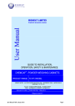
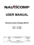
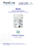
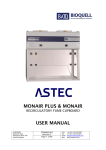
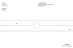
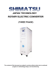
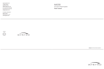
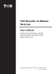
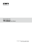
BIGNEAT LIMITED
SAFETY CABINET
USER MANUAL
GUIDE TO INSTALLATION,
OPERATION, SAFETY & MAINTENANCE
HORIZONTAL LAMINAR-FLOW CABINETS
PRODUCT RANGE:
HLFO 1.0, HLFO 1.5, HLFO 2.0
HLFP 1.0, HLFP 1.5, HLFP 2.0
Manual No & Rev: HLF001 Rev C
BIGNEAT LIMITED
4 & 5 PIPER’S WOOD INDUSTRIAL PARK
WATERBERRY DRIVE
266400
WATERLOOVILLE
HAMPSHIRE
[email protected]
PO7 7XU
www.bigneat.com
Publication Code: HLF 001/C
TEL. NO. +44 (023) 92
FAX NO. +44 (023) 92 263373
EMAIL:
WEBSITE:
1
BIGNEAT
____________________________________________________________________
Containm ent Technology
__________________________________________________________________________________________________________________________________________________________________________________________________________________________________________________________________________________________
CONTENTS
About this Manual
i
Safety Notes
ii
Choice of Correct Chemcap Filter
iii
___________________________________________________________________________________________________________________________________________________________________________________________________________________________________________________________________________________
SECTION 1
Introduction
Cabinet Identity
Quality Assurance
Validation protocol
SECTION 2
Product Specification
General Construction
SECTION 3
Installation
SECTION 4
Commissioning
Initial Cleaning
Operating the cabinet
SECTION 5
Safety Monitoring
Replacing a Main Filter
SECTION 6
Examination & Testing
______________________________________________________________________________________________________________________________________________________________________________________________________________________________________________________________________________
APPENDIX 1
Notes on UK COSHH Regulations
APPENDIX 2
Product Labelling
APPENDIX 3
Electrical diagrams (Sheets 1 & 2)
Publication Code: HLF 001/C
2
BIGNEAT
____________________________________________________________________
Containm ent Tec hnology
________________________________________________________________________________________________________________________________________________________________________________________________________________________________________________________________________________________
ii Safety Information
General
This manual is intended as a guide. Whilst every effort has been made to ensure that the statements made
are accurate, no responsibility can be accepted for any editing errors or omissions contained herein. They
are in accordance with the current knowledge we possess and are intended to provide information about our
products and their principal function. Options for use above and beyond their design specification cannot be
guaranteed.
Hazards
This equipment can cause danger through employment of high speed rotating fans and high voltages1.
Failure to observe the following recommendations will constitute an ELECTRICAL SHOCK HAZARD
Installation, Operation and Servicing
If the equipment is installed, operated and/or serviced in a manner other than as recommended by Bigneat
(the manufacturer), the electrical protection and/or the airflow integrity of the enclosure could become
compromised. Any such installation or use will invalidate all guarantees and warranties.
Protective Earth
The connection to the cabinet earth terminal must be provided by a permanent, assured low impedance,
safety earth supply and made before any other supply voltages are made.
Any subsequent disconnection of the Earth terminal (whether by accident or other cause) could make the
recirculating cabinet dangerous, under some fault conditions.
Maintenance and repair
Repair, adjustment or maintenance with safety or normally fixed covers removed whilst the cabinet is under
voltage should be avoided. Skilled personnel only, aware of the potential hazards involved, should carry out
these operations. No user-serviceable components are incorporated in this equipment.
Explosion & Fire risk
The equipment is not designed or certified for use in a potentially explosive atmosphere as defined in
European Atex Directive 94/9/EC. Also, it should not be relied upon to provide safe containment in the event
of fire caused by the process atmosphere. The end user must carry out adequate risk assessment to
determine the hazards posed by the processes to be undertaken.
UV-C wavelength exposure (fitted as an optional item)
UV-C
UV-C emissions are harmful to skin and eyes and reflective capabilities are high. They pose health and
safety hazards to operators and those in the vicinity. Operators and Health and Safety officers should be
made aware of the potential risks. The UV lamp emits no ozone.
1
defined in BS EN 61010: 2001 as voltages greater than 33 Volts AC, (46.7 peak) 70 Volts DC
Publication Code: HLF 001/C
3
BIGNEAT
____________________________________________________________________
Containm ent Technology
__________________________________________________________________________________________________________________________________________________________________________________________________________________________________________________________________________________
1. INTRODUCTION
B
igneat’s Horizontal Laminar Flow cabinets are advanced engineered clean air and containment products
utilising proven Filtration technology. Designed as freestanding equipment, they are built, tested and
approved to exacting industry standards, providing extremely safe and reliable equipment.
When used as part of a comprehensive laboratory safety routine and following the recommendations in this
operating manual, the cabinets will provide optimum operator and/or product protection from a range of
airborne contaminants together with extended filter life.
QUALITY ASSURANCE
All HLF Cabinets are subject to factory acceptance and installation-commissioning tests by our trained
engineers, in accordance with fully documented Quality Assurance Procedures and applicable National
Standards.
The integrity of the design, manufacture and performance of the filtration and airflow of
the cabinet, on leaving our works is assured.
ELECTRICAL SAFETY
The equipment is designed to comply with the requirements of BS EN 61010:2001 and the Low Voltage
Directive.
Rating label
The cabinet is fitted with the following self-adhesive Rating and CE Mark Label, which uniquely identifies the
equipment. The label should not be removed, as evidence of original Quality Assurance Tests and CE Mark
integrity may be affected.
CE MARK & RATING LABEL
Publication Code: HLF 001/C
4
BIGNEAT
____________________________________________________________________
Containm ent Tec hnology
2.0 PRODUCT SPECIFICATION-HLFO MODELS
HLFO Cabinet range for Operator Protection
During normal operation the two centrifugal fans [installed in the fan housing mounted on top of the cabinet]
develop a preset velocity horizontal airflow. This laminar type airflow is drawn horizontally (away from the
operator), through the HEPA filter mounted in the rear plenum and exits via an exhaust filter at the top of the
Fan housing recirculating back into the laboratory. See Figure 2.
General construction
The cabinet consists of a welded, mild steel Fan housing, containing the fans, variable speed controller,
lighting unit, wiring terminal grid and exhaust-filter grille panel.
The steel fan housing (incorporating a steel rear plenum containing the HEPA filter) is fitted onto a fire
retardant, safe-edge 8mm acrylic enclosure.
All steel is finished in oven-baked powder-coat gloss paint, colour White.
A HPL work surface is located at the bottom of the unit.
2.1 PRODUCT SPECIFICATION-HLFP MODELS
HLFP Cabinet range for Product Protection
During normal operation the two centrifugal fans [installed in the fan housing mounted on top of the cabinet]
develop a preset velocity horizontal airflow. This laminar type airflow is drawn horizontally (towards the
operator), via the HEPA filter mounted in the rear plenum and the pre-filter at the top of the Fan housing.
The filtration of the laminar airflow produces a clean environment within the enclosure before recirculating
back into the laboratory. See Figure 1.
General construction
The cabinet consists of a welded, mild steel Fan housing, containing the fans, variable speed controller,
lighting unit, wiring terminal grid and pre-filter grille panel.
The steel fan housing (incorporating a steel rear plenum containing the HEPA filter) is fitted onto a fire
retardant, safe-edge 8mm acrylic enclosure.
All steel is finished in polyester powder-coat gloss paint, colour White.
A high-pressure laminate work surface is located at the bottom of the unit
Publication Code: HLF 001/C
5
BIGNEAT
____________________________________________________________________
Containm ent Tec hnology
2.1 PRODUCT SPECIFICATION contd..
Type:
Laminar Flow-Product Protection
Laminar Flow-Operator Protection
Model:
HLFP 1.0
HLFP 1.5
HLFP 2.0
HLFO 1.0
HLFO 1.5
HLFO 2.0
External dimensions:
Cabinet width:
Cabinet depth:
Cabinet height:
1000 mm
762 mm
1160 mm
1500 mm
762 mm
1160 mm
2000 mm
762 mm
1160 mm
1000 mm
762 mm
1160 mm
1500 mm
762 mm
1160 mm
2000 mm
762 mm
1160 mm
Airflow velocity:
Filtration system:
0.4 m/s at filter face
HEPA Filter EN 1822 Class H14 99.997% at 0.3 micron particle size
Activated carbon, meets BS7989:2001 and AFNOR NFX-15-211 (Optional)
Fan type:
2 x Centrifugal Fan type: DAE225-CC01-02
Cabinet noise level:
< 60dBA
UV Light (optional):
UVc Germicidal type: Wavelength 253.7 nm
Lighting:
Operating voltage:
Compliance standard:
Publication Code: HLF 001/C
2 x 36W strip
220-240V 50 Hz Power: 600W
ISO 14644-1:1999 Class 5
6
BIGNEAT
____________________________________________________________________
Containm ent Tec hnology
Pre-filter
Unfiltered incoming air
Fan blower
HEPA filter
Rear plenum
Figure 1 Airflow profile-Product Protection
Publication Code: HLF 001/C
7
Exhaust grille
Filtered exhaust air
Fan blower
HEPA filter
Rear plenum
Figure 2 Airflow profile-Operator Protection
Publication Code: HLF 001/C
8
BIGNEAT
____________________________________________________________________
Containm ent Tec hnology
_____________________________________________________________________________________________________________________________________________________________________________________________________________________________________________________________________________________
3. INSTALLATION
Site Selection
The HLF cabinet should be placed well away from open windows, doors and other sources of disruptive air
changes, which may affect safe, consistent function.
Where there is a comprehensive choice of site, choose the cleaner environment, as this will reduce pre-filter
maintenance costs.
Warning! The installed filters should never be obstructed in any way.
Space and ventilation
The laboratory or workroom should of course be of sufficient size to provide ample space around the cabinet
to move and operate conveniently. The small but constant heat load generated by the fan and any lighting
will be easily dissipated in average room sizes.
General installation recommendations
Recommendations for installation for best performance of powder control cabinets are to be found in British
Standard: 7258.
Electrical connection
The cabinet should be connected to the electrical supply with the mains lead supplied, where there is a
requirement to use other cable then connections should be made in accordance with the following colour
code:
Green & Yellow Lead
Blue
Brown
Protective Earth
Neutral return
Live
Connect to a supply of 230 Volts, 50 Hz, single phase, 5 Amps maximum.
Publication Code: HLF 001/C
9
BIGNEAT
____________________________________________________________________
Containm ent Tec hnology
_________________________________________________________________________________________________________________________________________________________________________________________________________________________________________________________________________________
4.0
COMMISSIONING
Having connected the cabinet to the correct supply, switch ON by pressing the fan membrane switch, the
associated green LED should be illuminated and the fan running.
For the following commissioning procedures the fans should be allowed to run for several minutes in order to
stabilise, after which the airflow velocity can be set.
Measure the airflow velocity at the face of the HEPA filter using a suitably ranged and calibrated rotary-vane
type anemometer. The fan speed is pre-set during factory acceptance testing to provide an average velocity
at the filter face of 0.4 m/sec.
Initial Cleaning
Following commissioning, clean the interior with the fan running. The recommended method of cleaning
hard surfaces is by damp wiping which has been shown to have a removal efficiency of more than 99% on
particles of 5 µm, but is unlikely to pick up more than 10% of 10 µm particles.
Wipers should always be of the highest quality, non-shedding type suitable for clean room use. A variety of
purpose made clean room-cleaning products is on the market and manufacturers advice should be sought
for each application.
Warning! Do not attempt to clean the filter face. Although protected by a metal mesh, it remains
vulnerable to accidental damage and great care should be exercised at all times.
Publication Code: HLF 001/C
10
4.0
Operating the HLF Cabinet
On the control panel press the Fan switch to the ON position. The fan speed will eventually stabilise at the
level preset during commissioning.
Press the Light membrane switch to the ON position to illuminate the interior of the cabinet.
Using the UV lighting option.
To operate the germicidal UVc lighting, first insert the key into the UV light key-switch and select the UV light
position.
Rotate the Timer switch dial to the desired interval (max on period:30 mins)
UV-C
For safety, the normal (whitelight) lamp will turn off during UV operation.
Do not attempt to look beneath the metal safety screen directly at the UVc lamp or place hands/arms into the
cabinet during the cycle.
At the end of the cycle operate the keyswitch to Normal to allow normal lighting to resume (or to enable the
normal light to be switched on at the control panel).
BIGNEAT LTD
OK
LIGHT
FAN
FILTER
Blocked
HORIZONTAL
LAMINAR FLOW
SYSTEM
CONTROL PANEL
Publication Code: HLF 001/C
11
BIGNEAT
____________________________________________________________________
Containm ent Tec hnology
______________________________________________________________________________________________________________________________________________________________________________________________________________________________________________________________________________________
5.0
SAFETY MONITORING
Air Velocity
Over time, the progressive saturation of the filter will affect the laminar airflow velocity within the cabinet. The
airflow will eventually fall below the [0.4 m/s] level set during original commissioning and the ‘blocked filter’
warning lamp will illuminate.
Adjustment to the fan speed will compensate for the reduction in airflow within the remaining adjustment
range of the speed control.
Where a carbon filter option is installed take care in removing the filter as undue shaking or ‘jerking’ may
contaminate the local area with carbon dust.
The cabinet should be checked at intermediate periods with a calibrated anemometer.
Main Filter-changing
If, the blocked filter light continues to illuminate, the Main Filters must be replaced,
The used Main filters should be extracted after undoing the ten screws fitted around the periphery of the filter
clamp frame and within the enclosure.
‘Double bag’ and seal in a heavy-duty waste bag the used filters for disposal in accordance with your current
waste disposal procedures.
Safety Warning! Protective overalls, gloves, facemask and safety glasses should be worn throughout
these procedures.
Electrical Safety
The HLF Cabinet is tested as [Class 1electrical] appliance, and must continue to meet the requirements of
the Electricity at Work Regulations 1989. This includes the associated IEC mains cord set supplied and this
along with the electrical system of the safety cabinet should be examined frequently for signs of damage.
There should be regular formalised inspections carried out by a ‘competent’ person and must include earth
bonding and insulation tests.
Cleaning & Disinfecting
Cabinet enclosures should be cleaned (and disinfected if applicable) frequently and regularly. The
frequency of cleaning will depend upon the use to which the cabinet is put but as an indication cabinets for
non-organic use might be cleaned weekly. Those used for pharmaceutical procedures are normally cleaned
before and on completion of specific operations.
Switch off the fan. (Note: HLFO models can be safely cleaned with the fan running).
The recommended method of cleaning both acrylic and painted surfaces is by damp wiping with diluted
detergent and water.
This is shown to have a removal efficiency of 99% on particles of 5 µ m, but is unlikely to pick up more than
10% of 10 µ m particles.
Note: DO NOT use a solvent-based cleaning solution as this may promote stress cracking of the acrylic
material very quickly.
Wipers should always be of the highest quality non-shedding type suitable for clean room use.
Publication Code: HLF 001/C
12
BIGNEAT
____________________________________________________________________
Containm ent Tec hnology
___________________________________________________________________________________________________________________________________________________________________________________________________________________________________________________________________________________
UV lamp replacement
The UV lamp installed has an effective life of 6,000 hours at 80% relative UV output level.
Turn the power off and allow lamp to cool before replacement to avoid potential burn and
electrical shock hazard.
6.0
EXAMINATION & TESTING
COSHH Regulations
Current UK COSHH regulations recommended that this Safety Cabinet be examined, serviced and
revalidated at least once every 14 months and should include the following checks:
•
•
•
•
Average face velocity airflow and efficiency
Filter saturation and seal Integrity
Fan motor noise or vibration
Electrical safety, to include mains lead
Bigneat’s own Service Department has many years experience in Fume and Particulate Extraction
maintenance, test and validation. We would be pleased to quote you for an appropriate Service Contract.
Call our Service department on direct telephone number: +44 (0) 23 9224 6443 for further information and
advice.
Publication Code: HLF 001/C
13
BIGNEAT
____________________________________________________________________
Containm ent Technology
________________________________________________________________________________________________________________________________________________________________________________________________________________________________________________________________________________________
APPENDIX 1
NOTES ON UK COSHH REGULATIONS
1.
The “Control of Substances Hazardous to Health” (COSHH) 2004 regulations.
2.
The regulations are the UK implementation of an EEC Council directive 80/1107/EEC.
3.
The regulations require an employer to protect his employees and any other people (whether
working for him or not) from hazardous substances.
4.
A hazardous substance is defined as:a)
A substance or mixtures of substances, which are on the list of hazardous substances as defined by
the Classification, Packaging and Labelling Regulations 1994.
b)
A substance for which an Occupational Exposure Limit (OEL) value exists. This list is similar to US
threshold Limit value Levels (TLV).
c)
A micro-organism, which creates a health hazard.
d)
Dust at a substantial concentration in air.
e)
Any substance, which creates a hazard to health, similar to the hazards created by the substances
in a-d.
Note that paragraph 4e is a “catch-all” section.
5.
The employer is responsible for assessing the risk to an employee.
6.
The employer must prevent or control the exposure of an employee to hazardous substances.
7.
The control of exposure “shall be secured by measures other than the provision of personal
protective equipment”. This means the fumes must be contained, rather than providing protective
suits and masks to staff.
8.
OEL values must not be exceeded.
9.
The employer must ensure that safety equipment is properly used.
10.
The employee must use safety equipment provided correctly.
11.
The employer must maintain safety equipment in good working order. In particular:-
a)
Exhaust ventilation equipment must be examined every 14 months.
b)
Other safety equipment must be examined at “suitable intervals”.
c)
Records of checks, tests and repairs must be kept for 5 years.
12.
Monitoring of exposure to hazardous substances must occur “in accordance with a suitable
procedure”. Records of results must be kept for 5 years for general monitoring, and for 30 years
when they relate to a specific employee.
13.
Regular medical checks are required when working with certain listed substances, or where an
identifiable disease is associated with a certain substance.
14.
An employer must provide suitable instruction and training to employees regarding risks of
substances and precautions to be taken.
15.
Certain other regulations take precedence, such as Control of Lead at Work, Control of Asbestos at
Work, radioactive, explosive or flammable regulations, Mines and Quarries Act, and medical
treatment regulations.
Publication Code: HLF 001/C
14
APPENDIX 2
EQUIPMENT LABELLING
BIGNEAT LTD
OK
LIGHT
FAN
FILTER
Blocked
HORIZONTAL
LAMINAR FLOW
SYSTEM
MEMBRANE CONTROL PANEL
FILTER TYPE
SYMBOL
This cabinet is fitted with
Chemcap™ Filter
for use with particulates
H+
SHOULD YOU HAVE ANY QUESTIONS CALL +44 (0)23 92 266400
INSTALLED (OPTIONAL) FILTER IDENTITY (EXAMPLE)
Publication Code: HLF 001/C
15
BIGNEAT LIMITED
APPENDIX 3
HORIZONTAL AIRFLOW CABINET
ELECTRICAL SCHEMATIC DRAWING
REF: 67922 Sheet 1
DATE: FEBRUARY 2009
Z
NOTE!
UZ
The control panel that operates the Fan and Lighting circuits is not
shown.
U
Black
SPEED CONTROLLER
TYPE REE50
N
Blue
L
Brown
White
FAN BACKWARD CURVE
DAE225-CC01-02
1
PL1
J1
L
4
SW1
IC1
PRESSURE SWITCH
White
LK 1
1
N
FS1
3
J2
PCB TYPE 1951
Brown
L
Blue
N
FS2
Black
J3
L
FS3
N
J4
L1 White light
L
N
E
IEC FUSED
SOCKET
N1 White light
See sheet 2
Brown
SUPPLY
230 VOLTS
SINGLE PHASE
50Hz
L
L2 UV light
3.15A
Blue
N
N2 UV light
3.15A
Gn/Yel
E
IEC to UK plug
mains lead 2M
Publication Code: HLF 001/C
16
BIGNEAT LIMITED
HORIZONTAL AIRFLOW CABINET
ELECTRICAL SCHEMATIC DRAWING
REF: 67922 Sheet 2
UV-C
Warning!
UV-C Radiation from the biocidal
lamp
is harmful to both eyes and skin
NORMAL/UV
KEY SWITCH
NORM
L1
BALLAST
WHITE LIGHT
BALLAST
UVc LIGHT 15W 230V
L2
UV
30 min
UV TIMER
SWITCH
See sheet 1
N1/ N2
Publication Code: HLF 001/C
17
DATE: FEBRUARY 2009
WEEE Directive 2002/96/EC and
RoHS Directive 2002/95/EC
Waste Electrical and Electronic Equipment
(WEEE) Symbol
The use of the WEEE Symbol indicates that this product cannot be treated
as domestic household waste at end-of-life.
By ensuring that this product is disposed of correctly, you will help protect
the environment.
For more detailed information about the recycling/recovery of this product,
please contact your supplier, or Bigneat Ltd. directly.
Restriction of the use of certain Hazardous Substances
(RoHS)
Bigneat Ltd. has taken all reasonable steps to ensure that the product
does not contain any or more than the permitted maximum concentrations
of the six designated restricted hazardous substances namely, Pb, Hg, VI,
PBB, PBDE and Cd
Publication Code: HLF 001/C
18
ISO 9001
REGISTERE D FI RM
INTERNATIONAL
ACCREDITATION BOA RD
Certif icate No.GB200 13 86
Registration No . 004 4/1
Printed and Published by
Bigneat Limited
4 & 5 PIPERS WOOD INDUSTRIAL PARK
WATERBERRY DRIVE
WATERLOOVILLE
HAMPSHIRE
PO7 7XU
TEL: +44 (0) 23 9226 6400 FAX: +44 (0) 23 9226 3373
E-MAIL: [email protected]
WWW.BIGNEAT.COM
Publication Code: HLF 001/C
19