1
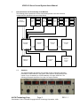
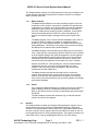
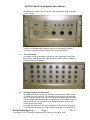
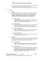
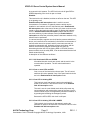
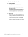
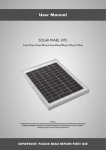
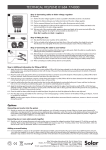
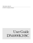
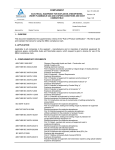
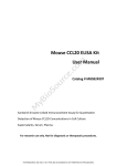
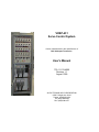
VDSP-431
Servo Control System
Custom manufactured to the specifications of
Bell Helicopter Textron Inc.
User’s Manual
730-11-013-4000
Revision 1.1
August 1999
ALPHI TECHNOLOGY CORPORATION
6202 S. Maple Ave. #120
Tempe, AZ 85283 USA
Tel: (480) 838-2428
Fax: (480) 838-4477
VDSP-431 Servo Control System User’s Manual
1.
Interconnections and Functionality of the Modules
The following picture represents all of the components present in the rack. All these
components are described in the rest of this section.
SCM
ANALOG
MULTIPLEXER
VDSP
431
SCM
SCM
VDSP
431
SCM
SETPOINT
MASTER
SETPOINT
SLAVE
READOUT
MODULE
1.1.
SCM
SCM
VDSP
431
SCM
SETPOINT
SLAVE
AC FRONT
PANEL
SCM
SCM
VDSP
431
SCM
SCM
SETPOINT
SLAVE
REAR AC
OUTLET
PANEL
Setpoints
The setpoint displays provide the user with the means of manually controlling
parameters in each channel of the system. Each setpoint module allows for the
control of up to 6 channels (on 3 SCM modules) of a single VDSP-431. The
following photograph shows the front view of a setpoint module.
ALPHI Technology Corp.
Page 2
Part Number: 730-11-013-4000 Copyright ALPHI Technology Corporation, 1999
SCM
REV 1.1
VDSP-431 Servo Control System User’s Manual
The Setpoint Module consists of a PCB populated as to the type of Setpoint, and
several auxiliary PCBs which interface the front panel controls in a consistent
manner with the main PCB.
1.1.1.
Master Setpoint
The Master Setpoint Module is the main controlling module in the rack
as pertains to user interface. It consists of a setpoint PCB populated for
configuration as a master, a PCI-4Pack module operating in embedded
mode with custom code for this application running on a C31 DSP, a
CIO-32 IP module which actually controls the hardware, a SCC-04B IP
which communicates with the VDSP-431, and a Greenspring IP to
provide non-volatile storage of settings between power cycles of the
rack.
The Master Setpoint, via the CIO-32 and the embedded code in the C31
on the PCI-4Pack, functions as a master on a parallel bus which
includes up to 3 Slave Setpoint Modules, the Readout Module, and the
Analog Multiplexer. This allows for the polling of the controls and setting
the displays for 24 channels and 4 readout displays.
The Master Setpoint communicates with the VDSP-431’s by two means.
First, a serial protocol is provided by which the VDSP-431’s are informed
as to the setpoint settings, and which parameters the user has selected
from the Readout Module, and allows the VDSP-431 to issue software
commands to set the conditions which will cause the AC power to be
removed from the test apparatus, and to reset from such a condition.
Second, the VDSP-431, via its parallel port, can poll certain hardware
conditions of the rack, such as the AC Interlock state, the user’s
selection of the AC power to the test apparatus, and fault and limit
conditions of the other VDSP-431’s.
The Master Setpoint provides the necessary logic to monitor the
interlock state, allow the user to control the AC power via front panel
controls, to provide the user feedback as to the status of the interlock
lines, and to provide the necessary logic and clock signals for the display
and interface hardware.
1.1.2.
Slaves
Up to 3 additional Setpoint Modules of the Slave type may be added to a
system, adding controls for 18 additional channels. It functions as a
slave on the interconnect bus to polls from the Master and its associated
PCI-4Pack.
The Slave Setpoint contains the necessary logic to read the interface
controls, and to drive the displays.
1.2.
Readout
The Readout Module consists of a Setpoint PCB populated to configure it as a
Readout Module and several auxiliary PCBs which interface the front panel
controls in a consistent manner with the main PCB. The Readout Module allows
the user to monitor various signals output from the VDSP-431 cards for any 4 of
the 24 channels present on a fully populated system. The signals are output from
each VDSP-431 by a pair of analog signals which are run to the Analog
ALPHI Technology Corp.
Page 3
Part Number: 730-11-013-4000 Copyright ALPHI Technology Corporation, 1999
REV 1.1
VDSP-431 Servo Control System User’s Manual
Multiplexer Module where they are switched to the appropriate display and
connectors of the Readout Module.
The Readout Module functions as a slave on the interconnect bus to polls from
the Master and its associated PCI-4Pack.
1.3.
Analog Multiplexer
The Analog Multiplexer Module is responsible for switching the analog signals
for Command and Parameter from each of the 24 channels of SCMs to the user
selected readout panel. It is located in the back of the rack mounted vertically.
ALPHI Technology Corp.
Page 4
Part Number: 730-11-013-4000 Copyright ALPHI Technology Corporation, 1999
REV 1.1
VDSP-431 Servo Control System User’s Manual
The Analog Multiplexer Module functions as a slave on the interconnect bus to
polls from the Master and its associated PCI-4Pack.
1.4.
1.5.
VME Chassis
Each VME chassis has sufficient room to support up to 12 channels. Additional
channels up to 24 can be added with a second chassis and boards. Slot zero is
empty, awaiting the customer’s controller card.
1.4.1.
VDSP-431
Please refer to the VDSP-431 controller manual.
1.4.2.
VDSP-SCM
Please refer to the VDSP-431 SCM manual.
AC Front Panel
The AC Front Panel Module allows the user to control and monitor the 3
switched AC outlets using the specified sequencing, to provide an emergency
power deactivation of the 3 switched AC outlets, and to provide visual status of
the 5 interlock circuits.
The AC Front Panel Module connects to the logic present on the Master Setpoint
Module to control the AC switching and primary emergency cutoff, and to light
the appropriate colors in the interlock LEDs.
ALPHI Technology Corp.
Page 5
Part Number: 730-11-013-4000 Copyright ALPHI Technology Corporation, 1999
REV 1.1
VDSP-431 Servo Control System User’s Manual
The AC Front Panel Module connects to the AC Rear Panel Module to provide a
secondary emergency cutoff circuit, and to provide visual indication of the status
of the three switched AC outlets.
1.6.
AC Rear Panel
The AC Rear Panel Module serves to distribute AC power from the line cord to
the appropriate places. It consists of the appropriate AC connectors, switch,
circuit breaker, contactors, and PCB to control AC power and interlock state.
AC power is input via a twist-lock connector as specified. Power is routed
through a two pole 15 Amp magnetic circuit breaker which also serves as the
power switch for the entire rack.
Three switched AC outlets are provided for the user to connect and control
external equipment. Power is switched via three contactors internal to the AC
Rear Panel Module. Total power delivered to the user’s equipment and the
internal power required by the rack is limited to 15 Amps. Control of these
contactors are via 7 relays on a PCB internal to the AC Rear Panel which are
controlled by logic on the Master Setpoint Module.
Five interlock connections are provided for connection to the user’s interlock
circuits. These circuits supply approximately 10 mA of current through normally
closed limit switches, and are optically isolated from the logic of the rack.
Interruption of any of the interlock circuits is reported to each of the VDSP-431’s
via the parallel connection to the Master Setpoint Module, and if enabled under
software control, will remove power to the switched AC outlets. If power is
removed from the AC outlets because of an interlock circuit opening, or because
of a fault or limit condition reported by any of the VDSP-431’s, the rack will
remain in a faulted state, ignoring any user requests via the AC Front Panel
Module, until either the software issues a reset, or the Emergency Power switch
is activated and released to reset.
One non-switched outlet (except through the circuit breaker) on the inside of the
rack provides AC power to the AC power rail internal to the rack. The DC power
supply for the rack, each of the VME chassis, and the fans for the rack are
powered from this rail.
Two switched outlets on the inside of the rack are provided (only one of which is
now being used) are controlled via a lighted rocker switch on the outside of the
AC Rear Panel Module. The transducer DC power supplies receive their AC
power via this outlet.
Connectors on the internal PCB are exposed via a cutout in the sheet metal of
the AC Rear Panel Module. A 50 pin ribbon cable is run to the Master Setpoint
Module logic to control the 7 relays driving the contactors, to monitor the state of
the three switched AC outlets, and to get the state of the five interlock circuits.
Discrete wires are run to the AC Front Panel to light the AC switches, and to
provide a secondary power interruption to the contactors when the Emergency
Switch is opened.
Logic is designed to prevent AC power from reaching the switched outlets in the
event of a critical connection internal to the rack opening via through
disconnection.
Additionally, if the cable connecting the Master Setpoint Module to the AC Rear
Panel Module internal to the rack is cut or removed inadvertently, or the AC
monitoring of the three AC outlets does not match the requested state, the logic
is designed to fault the AC control portion of the rack and to remove AC power to
ALPHI Technology Corp.
Page 6
Part Number: 730-11-013-4000 Copyright ALPHI Technology Corporation, 1999
REV 1.1
VDSP-431 Servo Control System User’s Manual
the switched AC outlets. The five interlock LEDs are blinked in RED to indicate
such a condition.
Controls are recessed approximately 2 inches to provide protection against
inadvertent actuation of controls located on the Rear Panel Module.
1.7.
Connection Panel
Connection Panels are provided to connect the user’s equipment to the SCMs
located in the VME chassis. Each panel allows for the connection of 8 channels.
Connector wiring is as specified.
1.8.
DC Power Supplies and Distribution
DC power for the rack is supplied by a multiple output switching supply located
on a shelf at the top of the rack. The transducer power supplies, also located at
the top of the rack, provide +15 and -15 volt power to the appropriate connectors
on the Connection Panel Module, and is controlled via a rocker switch on the AC
Rear Panel Module. The transducer power supplies are fused via inline fuse
holders located on the shelf.
DC power is brought to the DC Power Distribution Panel, where all connections
to the remainder of the rack are made. Individual wires are run to each Module
ALPHI Technology Corp.
Page 7
Part Number: 730-11-013-4000 Copyright ALPHI Technology Corporation, 1999
REV 1.1
VDSP-431 Servo Control System User’s Manual
in the rack which requires DC power. The DC Power Distribution Panel is located
on the back of the rack above the Analog Multiplexer Module.
The VME Chassis each have their own power supplies to power the VME cards.
2.
Operation
2.1.
2.2.
Setpoint
Each Setpoint Module allows for the setting of the percentage of command for 6
channels of output. Channels are numbered from left to right, and additional
channels are added going up. In other words, in a fully populated rack of 24
channels, the bottom setpoint controls channels 1-6, and the top setpoint
controls channels 19-24. Each channel consists of the following controls.
2.1.1.
Setpoint Display
The LED display shows the current percentage of the command for this
channel. Values range from -100.00 % to 100.00 % in 0.05 % steps.
Therefore, there are 4001 steps over the range.
2.1.2.
Setpoint Control
If the associated Enabled / Locked switch is enabled, the knob will adjust
the setpoint for the channel. If the switch is locked, the control is
ignored. Approximately 30 turns are required to move from limit to limit.
2.1.3.
Enabled / Locked Switch
When the switch is in the upward position, the control is enabled. When
the switch is in the downward position, the control is locked.
2.1.4.
Enabled Status LED
When the control is enabled, the LED will glow green. When the control
is locked, the control will glow red.
Readout
Any 4 of the 24 possible channels can be monitored at the Readout Module. The
Command signal is available for monitoring and one parameter may be selected
for that channel. Each readout consists of the following controls.
2.2.1.
Channel Display
Displays which channel that this readout is connected to. Will be in the
range of 1 - 24. No two readouts can be connect to the same channel.
2.2.2.
Channel Control
Used to select which channel to connect to this readout. You will notice
that as the control is turned, that any channel in use by the other three
readouts will be skipped over. This is intended behavior, and is to
enforce the fact that there is only one parameter output from each
channel of the VDSP-431 available for output.
ALPHI Technology Corp.
Page 8
Part Number: 730-11-013-4000 Copyright ALPHI Technology Corporation, 1999
REV 1.1
VDSP-431 Servo Control System User’s Manual
2.2.3.
2.3.
Parameter Control
Used to select which parameter is to be output from the Parameter Jack
and displayed on the Parameter Display. The following parameters can
be output and displayed.
FBKA
LVDT High Level Output.
FBKB
Bridge High Level Output.
ERROR
Servo Loop Error Signal.
VALVE
+/- 100% of current independent of range.
EXCA
LVDT Excitation Voltage divided by two. 10 Khz Sinusoid.
This parameter can be viewed only from the Parameter
SMB connector on the scope.
EXCB
Bridge Excitation Voltage. Parameter represents one side
of the differential excitation output.
CMD
Composite Command Signal.
LIMIT
Error Limit Signal.
2.2.4.
Parameter Display
DC Voltmeter which displays the output parameter selected by the
Parameter Control of the selected channel.
2.2.5.
Parameter Jack
SMB jack which drives the output parameter selected by the Parameter
Control of the selected channel.
2.2.6.
Command Jack
SMB jack which drives the output command signal for the selected
channel.
AC Front Panel
Allows the user to control the switched AC outlets and to monitor the status of
the interlock circuits.
2.3.1.
Emergency Switch
Forces the immediate removal of AC power from all three switched AC
outlets. Also can be activated and released to clear an interlock caused
removal of AC power.
2.3.2.
AC “ON” Switch
Momentary switch which operates in a press to activate / press to
deactivate manner.
The switch will not operate if there is an open interlock circuit on a circuit
which has the AC power interruption enabled for that circuit.
The switch will glow green when the AC “ON” power is active.
ALPHI Technology Corp.
Page 9
Part Number: 730-11-013-4000 Copyright ALPHI Technology Corporation, 1999
REV 1.1
VDSP-431 Servo Control System User’s Manual
Activation will cause AC power to be delivered to the first of the
sequenced AC outlets.
Deactivation will cause AC power to be removed from all three switched
AC outlets.
2.3.3.
AC “LOW” Switch
Momentary switch which operates in a press to activate / press to
deactivate manner.
The switch will glow amber/yellow when the AC “LOW” power is active.
Note that the AC “ON” power must be on, and the AC “HIGH” power
must be off for this switch to operate.
Activation will cause AC power to be delivered to the second of the
sequenced AC outlets.
Deactivation will cause AC power to be removed from second of the
sequenced AC outlets.
2.3.4.
AC “HIGH” Switch
Momentary switch which operates in a press to activate / press to
deactivate manner.
The switch will glow red when the AC “HIGH” power is active.
Note that the AC “ON” power and AC “LOW” power must be on for this
switch to operate.
Activation will cause AC power to be delivered to the third of the
sequenced AC outlets.
Deactivation will cause AC power to be removed from third of the
sequenced AC outlets.
2.3.5.
Interlock LEDs
There are five interlock LEDs which indicate the status of the five
interlock circuits as well as the health of the AC control circuitry. LEDs
are updated to reflect the current state for each interlock circuit
Each interlock circuit can be set for one of three modes under software
control. The LEDs will display different results depending upon the mode
selected. The modes are as follows:
Enabled with AC Interruption
If at any time (including if all three AC outlets are off) this interlock
circuit opens, the AC power will be removed to all three AC outlets. Rack
will be in test faulted state, which will prevent any application of AC
power, or proceeding with further tests. The first interlock which opened
will blink either RED or YELLOW depending on whether that circuit is
presently open or closed. Any other interlock LEDs will reflect their
current open or closed state with a solid RED or GREEN, or YELLOW,
(if enabled).
Enabled without AC Interruption
If at any time (including if all three AC outlets are off) this interlock
circuit opens, the test will not necessarily be faulted. AC power will not
ALPHI Technology Corp.
Page 10
Part Number: 730-11-013-4000 Copyright ALPHI Technology Corporation, 1999
REV 1.1
VDSP-431 Servo Control System User’s Manual
be removed in this instance. The LED for this circuit will glow RED or
GREEN depending if the circuit is open or closed.
Disabled
This interlock circuit is disabled, and has no effect on the test. This LED
is not glowing at all.
Enabled without AC Interruption mode is useful in several
circumstances. For instance, a hydraulic pressure switch may be
installed on one interlock circuit. If this interlock was in Enabled with
AC Interruption mode at the start of the test, AC power could never be
turned on, since the interlock would be open. By placing this interlock
circuit in Enabled without AC Interruption mode at the start of the
test, then switching it (under software control) to Enabled with AC
Interruption at some later point after pressure has been reached, a fully
safe test can be performed.
In a second example, suppose one circuit has the pressure switch from
above, and a second circuit consisted of a limit switch on the actuator. If
the limit switch was to be opened, and AC power was removed, the
hydraulic pumps would stop. Hydraulic pressure would drop, and the
interlock circuit with the pressure switch would also open. By
determining that the limit LED is blinking RED or YELLOW, and the
pressure switch circuit is solidly RED, it can be determined that the limit
switch caused the fault.
A description of the LEDs are as follows.
2.3.5.1. All illuminated LEDs are GREEN
All enabled interlock circuits are closed, and the rack is in the
normal mode of operation. The AC control switches are
operable.
2.3.5.2. One or more LEDs are RED
One or more of the interlock circuits are open. The AC control
switches will not be operable if any of the open interlock circuits
are in the Enabled with AC Interruption mode.
2.3.5.3. One LED is blinking RED
This interlock circuit has opened, causing the switched AC
power to be removed. This interlock circuit is in the Enabled
with AC Interruption mode.
The rack is now in a test faulted mode which will prevent any
test continuation until reset and the cause of the open circuit is
rectified. Reset may be accomplished by software command, or
by pressing and releasing the Emergency switch.
Because the LED is RED, this circuit is still open.
2.3.5.4. One LED is blinking YELLOW / AMBER
This interlock circuit previously has opened, causing the
switched AC power to be removed. This interlock circuit is in the
Enabled with AC Interruption mode.
ALPHI Technology Corp.
Page 11
Part Number: 730-11-013-4000 Copyright ALPHI Technology Corporation, 1999
REV 1.1
VDSP-431 Servo Control System User’s Manual
The rack is now in a test faulted mode which will prevent any
test continuation until reset. Reset may be accomplished by
software command, or by pressing and releasing the Emergency
switch.
Because the LED is YELLOW / AMBER, this circuit has now
been closed.
2.3.5.5. Any LED is YELLOW / AMBER
This interlock circuit previously has opened, but another
interlock or fault caused the switched AC power to be removed.
This interlock circuit is in the Enabled with AC Interruption
mode.
The rack is now in a test faulted mode which will prevent any
test continuation until reset. Reset may be accomplished by
software command, or by pressing and releasing the Emergency
switch.
Because the LED is YELLOW / AMBER, this circuit has now
been closed.
2.3.5.6. All five LEDs are blinking YELLOW / AMBER
One or more of the VDSP-431s has asserted either the fault or
limit line, causing the switched AC power to be removed. The
rack is now in a test faulted mode which will prevent any test
continuation until reset and the cause of the fault or limit is
rectified. Reset may be accomplished by software command, or
by pressing and releasing the Emergency switch.
2.3.5.7. All five LEDs are blinking RED
If the Master Setpoint Module has detected a serious problem
with the AC power control circuitry, the rack will indicate a
serious fault condition by blinking all five LEDs in RED.
This mode was instituted due to safety concerns.
Cycling power on the rack will reset this condition.
2.4.
AC Rear Panel
2.4.1.
AC Power Input
AC power is supplied to the rack via a Hubbell 2615 twistlock connector
from the power cord. A separate circuit rated at 15 Amps must provide
power to the rack to ensure maximum power available at the switched
outlets.
2.4.2.
Circuit Breaker
Input AC power is immediately run to a 15 Amp magnetic circuit breaker.
This also serves as the main disconnect for the rack.
ALPHI Technology Corp.
Page 12
Part Number: 730-11-013-4000 Copyright ALPHI Technology Corporation, 1999
REV 1.1
VDSP-431 Servo Control System User’s Manual
2.4.3.
Transducer Power Switch
A separate lighted rocker switch allows the transducer power to be
supplied to the appropriate Connections Panel connectors.
2.4.4.
Switched AC Outlets
Three AC outlets allow for the sequenced powering of external
equipment, and the interruption of power in the event of a possible
problem via the opening of an enabled interlock circuit or the VDSP-431
issuing a fault or limit condition.
Overall rack power is limited to the 15 Amps limit of the NEMA L5-15P
connector specified for the power cord. Therefore, the power available at
any given outlet is limited by the utilization of the rack power supplies,
the VME power supplies, and the other switched circuits. Internal wiring
and components are specified to allow for 15 Amp or more continuous
for any given switched outlet.
2.4.5.
Interlock Circuits
Five Bendix BT-2A connectors allow the user to connect normally closed
interruption circuits to the rack. If enabled by software, the opening of a
given circuit may cause interruption of AC power to the switched circuits.
In all cases, the current status of the interlock circuits are reported to the
VDSP-431’s present in the VME chassis.
If a particular interlock circuit is not being used, a shorting plug should
be installed. Alternatively, a particular interlock circuit can be disabled
under software control.
Interlock circuits operate on a 10 mA current loop and are optically
isolated from the circuitry in the rack as an attempt to prevent a possible
mishap.
ALPHI Technology Corp.
Page 13
Part Number: 730-11-013-4000 Copyright ALPHI Technology Corporation, 1999
REV 1.1