1
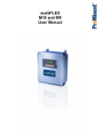
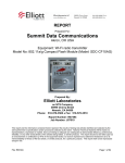
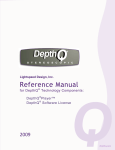
multiFLEX
Technical Manual
Updated June 23, 2015 - M714_Tech.doc
1
Contents: M714_Tech Manual
Safety
1. Installation-Commissioning
3.
1.1 Cabling – Wiring
1.2 LAN Communications
1.3 Modem Communications
1.4 Water Meters – Flowswitches – Contact Sets
2. Control Configuration
11.
2.1 Methods
2.2 Control Equations
2.3 Interlocks
2.4 Blocking Relays
2.5 Control Method
2.6 Special Controls
2.6.1 Bleed & Feed
2.6.2 Bleed then Feed
2.6.3 Percentage Time
2.6.4 Prebleed – Lockout
2.6.5 Captured Sample – Boiler Controls
2.6.6 Time Modulation
2.7.7 Timed Cycling
2.7.8 Holding Time
2.7 Timed Events
2.8 Variable Cycles
2.9 Feed Verification
3. Sensors
25.
3.1 Compensation
3.2 Calibration
4. System Configuration
4.1
4.2
4.3
4.4
28.
Power/Relay and I/O Modules
Installing Sensor & 4-20mA Drivers
System Settings
Module Testpoints
Appendix
34.
A. Resource Index
Updated June 23, 2015 - M714_Tech.doc
2
Safety
CAUTION: The operator of this instrument is advised that if the equipment is used in a
manner not specified in this manual, the protection provided by the equipment may be
impaired.
Electrical Shock Hazard
Opening the controller enclosure with the controller plugged in, exposes the
user to AC line voltages on the lower of the two controller circuit boards.
USER WARNING : CAUTION
Water Treatment Controllers operate steam and water valves and may pump
hazardous, corrosive and toxic chemicals. Opening the controller enclosure
exposes user to the risk of electrical shock at power line voltages.
Understand fully the implications of the control setpoints, interlocks and alarms that
you select. Harm to personnel and damage to equipment may result from misapplication.
Unplug or turn OFF the AC power to the controller if you have any concerns
regarding safety or incorrect controller operation and notify supervisory staff.
INDIVIDUAL CONTROLLERS
Controllers are supplied in many different configurations.
The HELP section in the M714_User manual contains the information for
terminating the sensors supplied with each controller.
The HELP section in the M714_User manual depicts the installation plumbing
header showing the sensor set supplied with each controller.
Updated June 23, 2015 - M714_Tech.doc
3
1. Installation-Commissioning
1.1 Cabling – Wiring
Controllers consist two circuit boards, an upper sensor module and a lower power module.
The top circuit board is either an M7, 7 Analog I/O & 6 digital Input or an M14, 14 Analog input &
12 digital input module. Both M7 & M14 include a LCD display and microcontroller module.
The lower circuit board is either a PR5, 5 Power Relay or PR10, 10 Power Relay module. Both
PR5 & PR10 include an alarm relay.
Controller Orientation
M14 - Analog-Digital
I/O Module
7, Dual
Analog I/O
Sockets
Modem
Serial Cable
LCD Display
Contrast
Relays
Enabled
RUN light
15-22 VDC
Supply for
Current
Loops
& Turbine
Meters
M7 Module
Relay 'ON'
neons
Alarm
Contacts
LAN
Link & Active
Lights
Ethernet
LAN
RJ45 Jack
Digital Inputs
'U' to 'Z'
Digital Inputs
'O' to 'T'
PR10 - Power Relay
Module
Line Fuse
Relays 6-10
Line Fuse
Relays 1-5
Field Wiring
Relays 1-3
Field Wiring
Relays 4-5
Relay 'ON'
neons
120-240VAC
Power In
Field Wiring
Relays 6-8
Field Wiring
Relays 9-10
120 VAC Controllers – Plug Box(es)
Updated June 23, 2015 - M714_Tech.doc
4
Controllers with pump controls are supplied one or more prewired120VAC plug boxes
Wired as shown in the following graphic. Individual plugs are labeled with the pump type;
Inhibitor, Acid Pump, Oxidant, Bleed etc.
PlugBox No.1
Red1
Green1
White1
GreenL
White3
Relay 8
Relay 9
Relay 10
R9 ON
R10 ON
Blue3
Relays 9 - 10
Updated June 23, 2015 - M714_Tech.doc
Green3
NC9 NO9 NC10 NO10
Blue3
Yellow3
Green3
R8 ON
Yellow3
Relay 7
Red3
R7 ON
Red3
Neutral
Brown3
White3
R6 ON
White3
Relays 6 - 8
Brown 3
PlugBox No.3
NO6 NC7 NO7 NC8 NO8
Red 2
Control
Fuse
Aluminum
Backplate
Fuse
6-10
Green3
Modem
AC
Power
Green2
Line
Voltage
Selector
GreenP
Green1
115
WhiteL
Power
Relay Module
Part# PR10
WhiteP
AC Input
BlackL
L N
Green2
BlackP
Fuse
1-5
Red2
Brown2
Power Cord
or
120VAC
Service
R4 ON
Brown2
NC4 NO4 NC5 NO5
Blue1
Relays 4 - 5
White2
Relay 6
R5 ON
White2
PlugBox No.2
Relay 5
Yellow1
Neutral
Green1
Blue1
Red1
RUN
Relay 4
R3 ON
Relay 2
Brown1
R2 ON
R1 ON
Relay 3
Relays 1 - 3
Relay 1
NO1 NC2 NO2 NC3 NO3
Yellow1
Alarm
Brown1
White1
AL1 AL2
White1
5
AC Power Wiring
Connect AC power ground to the aluminum backplate grounding screws located center, bottom.
Relay Neutral terminal blocks are commoned to the AC power input terminal N.
When a relay is ON, the NO terminal is at AC input L voltage and the neon light is ON.
When a relay is OFF, the NC terminal is at AC input L voltage and the NO terminal is
disconnected.
Analog Sensor Wiring
Each analog sensor, Conductivity, pH, ORP, Corrosion Rate, is identified by a letter A..N.
Assigning a fixed letter to each sensor, allows the user to modify the sensor name while
maintaining the physical location of the sensor driver and field wiring terminals.
The user manual HELP section includes wiring information specific to the controller part number.
Sensor E
Sensor F
Sensor D
Sensor C
Sensor A
Sensor B
Sensor G
M7 Module
Sensor Locations
Sensor K
Sensor L
Sensor I
Sensor H
Sensor C
Sensor J
Sensor G
Sensor D
Sensor N
Sensor F
Sensor A
Sensor M
Sensor E
Sensor B
M14 Module
Sensor Locations
M7 Module
Updated June 23, 2015 - M714_Tech.doc
6
Analog Sensor Wiring
Sensor Type
Conductivity & Temperature
Driver
Type
CT
Boiler – Condensate
Conductivity
B
PH, ORP
OP
Sensor 1
wiring
Red to S+
Black to SWhite to T+
Green to T-
Sensor 2
Wiring
No sensor 2
Black to S1
White to S1
Not polarized
Black to S2
White to S2
Not polarized
Coax Center to 1+
Shield to 1Solution ground
Coax Center to 2+
Shield to 2Solution ground
to
to
Corrosion Rate
CR
Red to S1
Black to S1
Not polarized
Red to S2
Black to S2
Not polarized
4-20mA inputs
CI
Loop + to 1+
Loop + to 2+
Loop – to
Loop – to
+ Out to 1+
- Out to 1-
+ Out to 2+
- Out to 2-
4-20mA outputs
IO
Auto polarity correction
Wiring Rules
Analog sensors, contact sets, water meters and flowswitches may be cabled in a common conduit
without causing operational problems.
Do not mix AC Line, 120VAC & 240VAC wiring with any sensor or communications cable in a
common conduit.
Grounded, metallic conduit is preferred in areas where variable frequency drives operate.
Sensor cables, with the exception of pH sensors, may be extended in paired AWG22, 0.25mm2
cable. Ensure that cabling splices are accessible in conduit fittings or junction boxes.
Verify that the shields on contact head water meters are also spliced when meter cables are
extended.
Updated June 23, 2015 - M714_Tech.doc
7
1.2 LAN Communications
Controllers not connected to a
network may be browsed
using a crossover cable and a
notebook’s or local PC’s browser
Refer to Application note
AN_T004 for detail on notebook
browser set-up.
Controllers use a static IP address to communicate using TCP/IP 10 base T.
Site IT provides LAN IP addresses and they may also wish to modify the ports used for HTML (default
80) and Telnet (default 23) . They may also require the controller MAC.
Key ENTER @ System and DOWN to ‘LAN Setup’ to view & modify IP, Netmask & Gateway.
MAC, HTML & Telnet ports are view only. Ports can be modified using a browser connection.
CAUTION: Exercise caution in making the controller Internet accessible. At a minimum, modify the
factory default passwords for Admin and Users 1-7, before making a controller Internet accessible.
Updated June 23, 2015 - M714_Tech.doc
8
1.3 Modem Communications
1.3.1 Installation
Terminate the site telephone service in an RJ11 jack and plug it into the LINE modem jack.
Modem
Serial Cable
Back of
Modem
Cabling
AC IN
Modem
Power
Cube AC
Line Phone
Phone
Line IN
Modem
Serial Cable
M7 - Analog-Digital
I/O Module
Control
& Modem
Fuse
PR5 - Power Relay
Module
Modem
AC
Power
Neutral
Modem
Fused
AC Power
Modem
Modem power cube :
WHITE to neutral
BLACK to Modem AC Power
Status LEDS
Updated June 23, 2015 - M714_Tech.doc
Modem
ON/OFF
Switch
9
1.3.2 Modem Test
Controller Power Up:
Modem Status LEDs: ON red MR,HS,TR,AA & green PWR
OFF red CD,OH,SD,RD
Press modem power switch if no status LEDs ON
Browser: Select Communicate/Diagnostic; displays OK, verifying modem power ON & controllerto-modem serial connection operational.
Dialing in to a Controller Modem
Dial in to a controller requires an application like Trackster, which will make the telephone
connection and then switch to Telnet for controller command and control.
If you manually dial a controller, it will pick up, time out and hang up because it cannot establish a
modem-to-modem connection.
Browser Dial-Out Test Sequence
1. Select Communicate/Modem Setup and verify that a phone number exists in one of the four
dial out slots. If no phone numbers exist, select Modify No.1, add Phone# & Submit. If you wish
to test Page out, check Pager before Submit. Entering your cell phone# and selecting Pager is
a simple test that verifies the site telephone service.
2. If you selected Pager, you now have the option to change the pager message (max 4 numbers)
and modify the Pager Delay (max 250 seconds). Pager delay in seconds occurs after the
number has been dialed and before the pager message is sent.
3. Start the modem test by selecting Communicate/Diagnostic & set Force Dial-Out to YES, select
one of the four phone numbers then submit.
4. Key Refresh frequently if you wish to follow the test sequence. If for example you do not have a
phone line connected to the modem & Pager has been selected, you’ll view ‘Testing’, ‘Pager
Dial-out’ and ‘NO DIALTONE’ in sequence.
5. If Pager is selected, the controller modem will dial the target phone#, wait the pager delay,
send the pager message & hang-up.
6. If Pager is not selected, the controller modem dials out, expecting to connect to another modem
at 19200. After connecting, the controller will send Controller Serial#, System Name, Location
Name, Date, Time, Active Alarms one per line and then hang-up.
7. Each alarm line is comprised of an I/O Letter or Number, Name, Alarm type, Date, Time alarm
tripped. Note that I/O points with ‘dial-out on alarm’ checked will dial-out every 60 minutes until
cleared.
8. Delays of several minutes occur between sequential modem tests to allow for recovery from
fault conditions; no carrier, loss of carrier detect…
Updated June 23, 2015 - M714_Tech.doc
10
1.4
Water Meters – Flowswitches – Contact Sets
Water meters, flowswitches and contact sets are connected between input terminal ‘O’ through ‘Z’
and a ground terminal. 5VDC limited by 10K puts 1/2mA through a closed contact set.
Hall effect Turbines and Paddlewheel water meters are powered by the 15-22VDC controller supply,
thermally fused at 100mA.
Seametrics type
Turbine Water
Meters
Contrast
White
U VW X Y Z
Black
LNK ACT
Red
LAN 15 VDC
Flowswitches
& Interlocks
CR2032
Green
Red
M7 Module
Black
O P Q R S T
Red
15 VDC
Black
Sensor Module
Contact Head
Water Meters
C&D
Water Meters, Flowswitches and
Contact Sets may be connected any
digital input 'O' to 'Z'
Connect cabling shields at the controller ends of the cable only, to any ground terminal either on the
M7 or M14 module or on the aluminum backplate, bottom, center
Updated June 23, 2015 - M714_Tech.doc
11
2. Control Configuration
2.1 Methods
2.1.1 ON/OFF: RELAYS
Relay Outputs 1..10 without a control equation are OFF unless turned ON by a timed event,
priming, bleed and feed, bleed then feed, percentage time or pre-bleed.
Sensor Control:
ON-OFF setpoint control by sensors A..N.
Control equations combine up to four sensor A..N.
Modified by 2.5 Control Method.
Volume Control:
Measure setpoint Volume then turn ON for setpoint Seconds.
Measure setpoint Volume ‘O’ then turn ON for setpoint Volume ‘P’
Control equations combine up to four meters O..Z.
Status Control:
Turn ON setpoint seconds after contact set closes
Timed Controls:
Biocide Timing turn ON for user set period at user set Day & Time
Prebleed and Lockout on each Biocide timed event.
Bleed & Feed and Bleed then Feed based on bleed ON time.
Percentage ON time in every 5 minutes.
Detailed in 2.6 Special Controls.
2.1.2 PROPORTIONAL: 4-20 mA OUTPUTS
4-20mA Outputs C1..C8 without a control equation, in AUTO mode, are 4mA.
Sensor Control:
Analog sensor A..N, using the sensor value to control current level.
Relay Control:
Relay 1..10 using the value of the relay control equation to control current level.
Auto / Manual:
Switch between user set Manual % output and automatic control by Sensor or Relay value.
2.1.3 USEABLE, NON-EXISTANT I/O
Analog and Digital inputs and Relays that do not physically exist can be used for logging and
control or as placeholders for blocking or as 4-20mA controls.
Examples:
Input ‘M’ in an M7 controller is used to log the results of a manual inhibitor ppm test.
Relay 8 in a PR5 controller is controlled by a ‘C’-‘D’ temperature difference and the difference is
used to control a 4-20mA output.
Water ‘V’ in an M7 controller is used to log the volume measured as GPM on analog input ‘E’.
Input ‘E’ compensation is set to Rate-to-Volume’, targeting input ‘V’.
The resulting volume on ‘V’ is used to control relay 1 Inhibitor pump feed.
Updated June 23, 2015 - M714_Tech.doc
12
2.2 Control Equations
There are three types of sensors used for control, Analog Sensors A..N, Watermeters O..Z and
Contact Sets O..Z. Sensor types cannot be combined in a Control Equation.
The first Input letter of the Control Equation is used to provide the Output units and resolution,
grouping within the Browser view and LCD Display sequencing.
The controller blocks illegal control equations.
Control equations are verified on power up and Load from Flash.
Illegal control equations are removed.
Sensors used in control equations cannot be disabled.
Analog Sensors A..N:
Operators: + Sum, - Difference, / Division, *Multiply
Control Equation limited to four Inputs and three Operators.
The first letter of a control equation must be a letter A..N.
All sensors used in a control equation must be enabled.
The relay ON/OFF state on setpoints is controlled by 2.5 Control Method
Examples: E/F A+B/C*D
G-N
Watermeter Sensors O..Z:
Operators: + Sum, - Difference, : Sequence
Sum & Difference control equations limited to four meters.
The first letter of a control equation must be a letter, water meter O..Z.
All water meters used in a control equation must be enabled.
Volume – ON Time Example:
Measure Water Meter Volume 200. Then Turn ON for 15 seconds.
Turn ON times accumulate & are displayed as Time Owed
Sequence Example:
O:P, measures a volume on O and the turns ON until the turn OFF volume
is measured on P.
Sequence can be used for Water Meter Cycle Control and for volumetric chemical feeds:
Measure 100 Gallons, Feed 10mL.
Contact Sets O..Z:
Limited to one letter O..Z
Turn ON setpoint seconds after the contact set closes.
Turn OFF setpoint ignored.
Example:
Control equation = T. Turn ON setpoint = 30.
Relay turns ON 30 seconds after contact set ‘T’ displays ‘ON’ and stays ON until contact
set T displays ‘OFF’.
Updated June 23, 2015 - M714_Tech.doc
13
4-20 mA Output Controls:
Control equation may be one of an analog sensor A..N
OR
A Relay number 1..10. If a Relay number is used then the current value of the
relay control equation is used to control the current level.
Current Output in mA = 4mA + 16mA x ( Sensor Value – 4mA Value) / ( Span )
Example:
Current Output C2 is controlled by pH sensor connected to input ‘E’.
Tower pH ‘E’ = 7.91 pH
C1 is set to AUTO with 4mA = 5 pH and 20mA = 10.
C1 output current is 13.3mA [ 4mA + 16mA x ( 7.91 – 5 ) / ( 10 – 5 ) ]
Updated June 23, 2015 - M714_Tech.doc
14
2.3 Interlocks
When an Interlock contact set OPENS, the interlocked relay turns OFF
When an Interlock contact set OPENS, the interlocked 4-20mA output is 4mA
An open interlock contact set displays OFF. A closed interlock contact set displays ON.
Interlocks may be used with all three types of controls; analog sensors A..N, water meters O..Z
and contact sets O..Z.
Note:
4-20mA outputs are limited to a single interlock O..Z,
ANDing & Oring interlocks does not apply to 4-20mA outputs.
Contact sets used in Interlocks cannot be disabled.
Example: Relay 2 controls a bleed solenoid. It’s interlocked with contact set T.
Contact set ‘T’ would typically be a flowswitch.
When contact set ‘T’ opens & displays OFF, Relay 2 will turn OFF or will not turn ON.
The state on Relay 2 will be ‘Interlocked T’ when T is OFF.
‘OR’ing contact sets:
If any one of the OR’ed contact sets is ON, the relay can turn ON.
Up to four contact sets may be ‘OR’ed
The forward slash, ‘/’ separates ‘OR’ed contact sets
Example: Boiler Steam Line Treatment pump is interlocked with contact sets T/X/Y
The pump can operate whenever any one of T, X or Y is ON.
Typically T, X & Y are ON whenever boilers 1, 2 or 3 are ON.
‘AND’ing contact sets:
All of the AND’ed contact sets must be ON, before the relay can turn ON.
Up to four contact sets may be ‘AND’ed
The plus sign, ‘+’ separates ‘AND’ed contact sets
Example: A pH control operates when both Y+Z contact sets are ON
Where Y & Z are ON when both the transfer pump and the tank full contact sets are
closed.
Updated June 23, 2015 - M714_Tech.doc
15
2.4 Blocking Relays
When a blocking relay turns ON; it turns OFF, blocks, the relay with that relay number in it’s
blocking field.
Example: Relay 1 feeds an inhibitor and has Relay 3 set in its Blocking field.
Relay 3 feed oxidant and has ‘none’ set in its Blocking field.
Whenever Relay 3 turns ON, Relay 1 turns OFF.
More than one blocking relay:
Up to four blocking relays may be set in any relay’s blocking field as 2+4+8+9 where
2,4,8 & 9 are enabled relays.
The ‘+’ sign separates more than one blocking relay
The controller prevents a relay from blocking itself.
2.5 Control Method
Sets the deadband response of an ON/OFF relay control
Applies only to relays controlled by sensors A..N
Method
Function
Examples
Rising Setpoint
ON: Sensor > Turn ON Setpoint
OFF: Sensor < Turn OFF Setpoint
Tower Bleed
Boiler Blowdown
Condensate Bypass
Acid Feed
Falling Setpoint
ON: Sensor < Turn ON Setpoint
OFF: Sensor > Turn OFF Setpoint
Oxidant Feed
Caustic Feed
Between Setpoints
ON: Sensor < Turn ON Setpoint
& Sensor > Turn OFF Setpoint
OFF: Sensor > Turn ON Setpoint
Sensor < Turn OFF Setpoint
Blocking Controls
Level Controls
Event Rising
Rising Setpoint
Acid wash – flush
Operates only during Timed Events Cleaning controls
Event Falling
Falling Setpoint
Oxidant slug feeds
Operates only during Timed Events
Event Between
Blocking – sequencing
Between Setpoints
Operates only during Timed Events controls
Updated June 23, 2015 - M714_Tech.doc
16
2.6 Special Controls
2.6.1 Bleed & Feed
Application: Pumps cooling tower inhibitor proportional to tower load.
The longer the bleed solenoid is ON the more inhibitor is pumped.
Setup:
Operation:
Notes:
User selects Inhibitor Pump relay & selects Bleed & Feed Special Control
User sets bleed solenoid relay number.
User sets % of bleed time 1-100%
Inhibitor Pump turns ON when Bleed Solenoid Relay turns ON.
Turns OFF when % ON time is exceeded in every 300 seconds.
If % of Bleed = 40%, Inhibitor Pump would be ON for 120 seconds
in every 300 seconds of Bleed ON time.
Bleed & Feed use is limited to sites where the bleed OR the inhibitor pump is
undersized and there not enough time between bleed periods to pump inhibitor.
Bleed then Feed is the preferred inhibitor feed method for sites, which do not
have a make-up water meter.
Sites which have wide variation in make-up conductivity typically will have
problems maintaining the target inhibitor level using Bleed & Feed.
Poor location of feed point and bleed take-off may result in inhibitor being
pumped down the drain.
Bleed setpoint dead band should be set to 1% for short bleed and short feed
periods.
2.6.2 Bleed then Feed
Application: Pumps cooling tower inhibitor proportional to tower load after the bleed solenoid
turns OFF.
The longer the bleed solenoid is ON the more inhibitor is pumped.
Setup:
Operation:
Notes:
User selects Inhibitor Pump relay & selects Bleed then Feed Special Control
User sets bleed solenoid relay number.
User sets % of bleed time 1-100%
Inhibitor Pump turns ON after Bleed Solenoid Relay turns OFF.
Turns OFF when % of Bleed ON time is exceeded.
If % of Bleed = 60% and Bleed was ON for 8.6 minutes, the Inhibitor Pump
would pump for 310 seconds ( 0.6 x 8.6 x 60 sec/minute).
Bleed then Feed is the preferred inhibitor feed method for sites that do not have
a make-up water meter.
Do not use Bleed then Feed at sites where the bleed or inhibitor feed pump is
undersized. There will not be enough time between bleed periods to feed
inhibitor.
Sites which have wide variation in make-up conductivity typically will have
problems maintaining the target inhibitor level using Bleed then Feed.
Bleed setpoint dead band should be set to 1% for short bleed then feed
periods.
Updated June 23, 2015 - M714_Tech.doc
17
2.6.3 Percentage Time
Application: Base feeds chemicals by cycling a relay ON/OFF every 5 minutes.
Reliable method of control for static systems or where users manually adjust
feed rates in response to on-site testing or process changes.
NOTE: Particularly useful where a contact set or flowswitch opens when the
system is offline. % Time controls do NOT accumulate time when the interlock
is OFF.
Setup:
Operation:
Notes:
User selects relay & selects the Percentage Time Special Control
User sets % of ON Time 1-100%
Every 5 minutes, 300 seconds, the relay will turn ON for the user set %.
If % ON time = 24%, relay would be ON for 72 seconds in every 300 seconds.
If the interlocking contact set opens, the relay will turn OFF and % Time is
suspended in it’s current state, resuming when the contact set closes.
Commonly used method to feed boiler chemicals where a contact set closes
when the boiler is on-line. Typically boiler chemistry is verified by the operator,
adjusting % time as required.
2.6.4 Prebleed – Lockout
Application: Prebleed lowers the tower conductivity before a biocide is fed to prevent
bleeding and subsequent biocide loss or dilution during biocide kill time.
Lockout prevents the bleed from operating during the biocide kill time.
Prebleed and Lockout execute on every timed event.
Setup:
Operation:
Example:
User selects Biocide pump relay & selects Prebleed-Lockout Special Control
User sets Bleed Relay number. This is the relay that will be Prebled and then
Locked Out every time a Biocide Event occurs on the Biocide pump relay.
User sets Lock-out time in minutes. Zero minutes = no lockout.
User sets Prebleed time in minutes. Zero minutes = no prebleed.
User sets prebleed conductivity OR ‘none’ if Prebleed is to be based on time
only.
User sets prebleed conductivity value.
Prebleed time starts when the timed event is scheduled on the Biocide relay.
Prebleed ends when the target conductivity is achieved or when the prebleed
time completes.
Biocide turns ON for the user set time.
Lockout starts at the start of the Biocide timed event.
Biocide Event on relay No.4 starts at 07:00 for 30 minutes
Prebleed Relay No.2 is set for 30 minutes & 750uS on Conductivity Sensor ‘E’.
Lockout time is set for 120 minutes.
At 07:00, Relay No.2 turns ON and the tower conductivity start to decrease.
At 07:20, the Tower Conductivity is 749uS.
At 07:20, Relay No.2 Bleed turns OFF and is Locked Out until 09:20.
At 07:20, Relay No.4 Biocide Pump turns ON
At 07:50, Relay No.4 Biocide Pump turns OFF
At 09:20, Relay No.2 can turn ON when the conductivity exceeds the Turn ON
Setpoint.
Updated June 23, 2015 - M714_Tech.doc
18
2.6.4 Prebleed – Lockout
Notes:
continued
The time required to lower the tower conductivity is dependent on tower load.
Subsequently, most biocides are fed early in morning when cooling towers are
not loaded.
Typical Lockout times of four hours may be a problem if tower load increases.
Since the bleed cannot operate, tower conductivity may exceed chemistry
limits.
2.6.5 Captured Sample – Boiler Controls
Application: Captured Sample controls boiler blowdown using a conductivity sensor installed
in a boiler’s surface blowdown line, upstream of the blowdown valve.
An optional Fail-to-Sample sensor detects a failure to open the blowdown valve
or an inadvertently closed isolation valve.
Setup:
Operation:
Notes:
User selects Blowdown Valve relay & selects Captured Sample Special Control
User sets Sampling time in seconds, typically 30-60.
User sets Measure time in seconds, typically 60-120 seconds
User sets Blowdown time in seconds, typically 60-300 seconds
User sets Re-Sample delay in minutes, varies with boiler type and service from
30 minutes to 720 minutes (12 hours).
User sets location of optional Fail-to-Sample sensor, a contact closure input
from ‘none, through ‘O’ to ‘Z’.
Captured Sample Blowdown Control is a four step process:
SAMPLE: The blowdown valve opens, purging the surface blowdown line and
delivering a sample of boiler water to the conductivity sensor.
MEASURE: The blowdown valve closes, the sample at the sensor cools & at
the end of the Measure period, the controller measures the conductivity.
If the conductivity is greater than the Turn ON Setpoint, go to Blowdown else go
to Re-sample.
BLOWDOWN: The blowdown valve opens for a user set time then the
controller goes to Measure.
RE_SAMPLE: The blowdown valve is closed for a user set time and then the
controller goes to Sample.
FAIL-TO-SAMPLE: An optional normally open thermal switch, installed opposite
the conductivity sensor, closes at nominally 200F, 95C. The controller checks
the state of the Fail-to-Sample switch at the end of the Measure period. A
closed Fail-to-Sample switch indicates a functioning blowdown.
As long as the measured conductivity is more than Turn ON Setpoint the
controller will repeat the Measure-Blowdown-Measure-Blowdown cycle.
The Measure period provides thermal compensation. The initial temperature is
fixed by the boiler pressure. A rapid, but repeatable temperature drop occurs
during the Measure period.
Updated June 23, 2015 - M714_Tech.doc
19
2.6.6 Time Modulation
Application: Cycles a chemical feed pump ON/OFF, decreasing the ON time as the
controlling sensor approaches the Turn OFF setpoint
Typically used for pH control, reducing acid feed as the Turn OFF setpoint is
approached.
Setup:
Operation:
Example:
Notes:
User selects a relay & selects Time Modulation Special Control
User sets Time Period in seconds, minimum 60, maximum 600 seconds.
Relay ON time = [ (Control – Turn OFF Setpoint) / Deadband ] x Period
where Deadband = Turn ON – Turn OFF setpoints.
Relay ON 100% of Period when Control is greater than Turn ON setpoint
Relay is OFF when Control is less than Turn OFF setpoint.
Acid Pumps Turn ON = 10 and Turn OFF = 8. Period = 120 seconds
At pH >= 10, Pump ON for 120 seconds in every 120 seconds
At pH = 9.5, Pump ON for 90 seconds in every 120 seconds
At pH = 9.0, Pump ON for 60 seconds in every 60 seconds
At pH = 8.5, Pump ON for 30 seconds in every 120 seconds
At pH <= 8.0, Pump OFF
Time Modulation control is not applicable when the system response time is
faster than 5x the Period. In the previous Example; If the measured pH moves
from 10 to 8 in less than 300 seconds, Time Modulation may not improve
control.
Process buffering, pump setting, feed point and system volume all affect the
response to chemical feed.
Time modulation also works on Falling Setpoints.
2.7.7 Timed Cycling
Application: Large volume systems where the response to a chemical feed or control action
is delayed in time.
Swimming pool pH, conductivity and ORP controls are typical applications.
Setup:
Operation:
Example:
Notes:
User selects a relay & selects Time Modulation Special Control
User sets ON Time in minutes, minimum 1, maximum 360 minutes.
User sets Period in minutes, minimum 1, maximum 360 minutes.
Controller forces Period >= ON Time.
Setpoint Controls turn ON the relay.
Time Modulation turns OFF the relay after ON Time minutes.
Time Modulation keeps the relay OFF for ‘Period – ON Time’ minutes.
During the OFF period, the system has time to respond to the ON Time feed.
Time Modulation ON Time = 10 minutes, Period = 60 minutes
Brine feed is controlled on conductivity using a Falling Setpoint.
Conductivity setpoint control turns ON the Pool Brine feed relay.
After 10 minutes the Pool Brine feed turns OFF.
After another 50 minutes the Pool Brine feed turns ON for another 10 minutes if
below the Turn ON setpoint or remains OFF if the conductivity is above the
Turn OFF setpoint.
Condensate systems are also slow to respond to amine feed.
However the response time may vary with time of year and steam production.
Updated June 23, 2015 - M714_Tech.doc
20
2.7.8 Holding Time
Application: Prebleed Holding Time averages the value of a control over a user-defined
period. Averaging lowers the effect of process transients and limits the effect of
the delay between feed and measuring the effect of the feed. Control of amine
feed by a pH sensor in the condensate return is a typical use of Holding Time
control.
Setup:
Operation:
Notes:
User selects relay & selects Holding Time Special Control
User sets averaging Period in minutes.
Minimum 30 and maximum 1440 minutes.
Holding Time controls use the controller data logs, limiting the control equation
to a single analog sensor A..N.
Controller retrieves the controlling sensor data log average entries for the most
recent Period. It averages the sensor value over the number of log entries and
uses the average for setpoint control.
If the number of log entries x log rate is less than Period, the controller uses all
of the available log entries.
If there are no log entries, the controller uses the current value of the sensor for
control.
The number of samples used for control is the Period / Log Rate.
Log entries are an average over the Log Period.
You may choose to reduce the Log Period to increase response to transients or
increase the Log Period to limit transient response.
The same effect may be achieved by altering the Holding Time Period.
Updated June 23, 2015 - M714_Tech.doc
21
2.7 Timed Events
Operation:
Timed events load ‘Time Owed’ with ON Time when they are scheduled.
Timed events always start on the minute.
If a timed event is prevented from turning ON a relay, it will turn ON when the
block clears or the flowswitch closes.
Time Owed is loaded after Prebleed if the Biocide Pump relay has the
Prebleed-Lockout Special Control selected.
Clear Alarms on a relay zeroes Time Owed, ending a timed event and
prebleed.
Clear Alarms on a Locked Out bleed relay will end the Lock Out
Timed events can operate in parallel with other controls. For example, a water
meter could add oxidant a low rate, proportional to load with a Timed event
providing a weekly slug feed.
Number of Events: Each relay 1..10 can have up to 28 timed events.
Start Time:
Each event has a user defined start time using a 24-hour clock with
1 minute resolution from 00:00 to 23:59.
ON Time:
User set relay ON time from 1 to 1440 minutes per event.
Prebleed-Lockout: Each biocide control relay can have its own prebleed-lockout timing,
user defined bleed relay and conductivity sensor.
Support for user with multiple systems or cooling towers.
For example: four towers with four bleeds and four biocide pumps, each of the
four with it’s own prebleed conductivity sensor.
Event Cycles:
Each relay can select a 1, 7 or 28 day event cycle.
You may elect to feed alternating organic biocides on a 28 day cycle,
daily oxidant on a 7 day cycle and an every 4 hour sensor wash on
a 1 Day cycle.
One day cycle is always Day 1.
Sunday is Day 1 for seven and twenty eight day cycles.
Twenty Eight day cycles have the option to set the most recent Sunday to
Day 1 using System/Configure command sequence.
Event Frequency: Varies with selected Event Cycle.
Allows user to quickly enter repeating events
1 Day Cycle: Once, Alternate Hours, Hourly
7 Day Cycle: Once, Alternate Days, Daily
28 Day Cycle: Once, Alternate Weeks, Weekly
Updated June 23, 2015 - M714_Tech.doc
22
2.8 Variable Cycles
Problem:
Tower make-up conductivity may change rapidly.
If hardness tracks make-up conductivity, then controlling a cooling tower on
tower basin conductivity may over cycle at low make-up conductivities and
under cycle at high make-up conductivities.
Overcycling may exceed water treatment chemistry for scale control.
Undercycling wastes water & increases sewerage charges.
Solutions:
Variable Cycles sets three ranges of cycles of concentration bleed control with
ranging switched on make-up conductivity.
Variable Cycles also sets a maximum tower basin conductivity that overrides
the cycle controls at high tower conductivities.
Setup:
User selects relay, Configure and sets the Variable Cycles.
User selects relay, Variable Cycles and sets:
Low Range: Makeup conductivity less than Low Range…
Low Cycles: Controls the bleed at Low Cycles
Med Range: Makeup conductivity between Low & Medium Range…
Med Cycles: Controls the bleed at Medium Cycles
High Range: Makeup conductivity between High and Medium Range…
High Cycles: Controls the bleed at High Cycles
Max Conduct.: Tower Conductivity greater than Max. Conduct controls the
bleed on tower basin conductivity.
Operation:
The controller overrides the Setpoint controls, modifying the setpoints in
response to make-up and tower conductivity levels.
Users are able to view, but not modify ON & OFF Setpoints.
A 1% deadband applies to both Cycles and Maximum Conductivity setpoints.
A ratio control equation is required, in the form of E/F where E = Tower Basin
conductivity and F = Makeup Conductivity.
If the control equation is not a ratio, the Special Control state will be set to
OFFLINE.
Notes:
Any ratio of analog sensors A..N may be used in a Varying Cycles control.
When setting Varying Cycles setpoints, calculate the time delay effect of system
holding time on bulk system chemistry.
A change in makeup conductivity may take considerable time to modify the bulk
chemistry of a cooling tower, particularly at low load.
Updated June 23, 2015 - M714_Tech.doc
23
2.9 Feed Verification
Controller Option. Field upgrade available.
Services:
Calculates and logs inhibitor ppm based on make-up volume, cycles of
concentration and volume of inhibitor fed.
Alarms on fail to feed inhibitor.
Calculates tank level, eliminates tank level sensing.
Application: Requires a feed meter on the output of the inhibitor feed pump.
Measures the make-up volume and feeds inhibitor based on user set control
mode.
Meters the volume of inhibitor fed and calculates current ppm based on fixed
cycles, meter cycles or bleed cycles on concentration
Reduces the inhibitor inventory by the volume of inhibitor fed.
Setup:
User selects relay, Configure and sets the Feed Verification.
User selects relay, Feed Verification and sets:
Verify Meter:
The water meter input O..Z connecting to the meter on the
output of the inhibitor feed pump.
Inventory location: The analog sensor input A..N used to log the calculated
inhibitor tank volume.
ppm location:
The analog sensor input A..N used to log the calculated
ppm
ppm method select:
Fixed Cycles: User sets a fixed number of cycles, default 3.500
Meter Cycles: User selects Bleed water meter input O..Z.
Uses the ratio of the tower make-up to the Bleed meter
as concentration for ppm calculation.
Bleed Cycles: User select Bleed Relay number 1..10.
Use the value of the Bleed Relay control equation as
concentration, assuming that the relay is controlled by
the ratio of Tower to Make-up conductivity.
Operation:
Assumes that the feed verification meter measures mL.
The controller calculates ppm based on the make-up volume fed from midnight,
the ml of inhibitor fed and concentration from the user selected ppm method.
Failure to measure volume after the relay has been ON for 30 seconds, sets a
Fail to Feed alarm on the Feed Verification meter.
Every 10mL of inhibitor fed reduces the inhibitor inventory. Inventory is
calculated in Gallons. If the metric units switch is set, inventory is calculated in
liters.
Notes:
The default feed verification meter provides 1 pulse/mL.
Any type of meter can be used for metering inhibitor feed and should calibrated
for mL/pulse or contact closure.
PPM can be corrected for inhibitor concentration by calibrating the ppm analog
input for the % active.
Do not calibrate the feed verification meter input for % active.
Updated June 23, 2015 - M714_Tech.doc
24
2.10 Priming
Setup:
Select the target relay using either the keypad or the browser.
Then select Diagnostics.
Keypad users set Time Owed to 5 minutes on selecting Prime.
Browser users can set the Prime time in minutes.
Operation:
Time Owed > 0 minutes, immediately turns ON the relay.
SAFETY: Interlocked relays will not turn ON until the interlock contact set
closes.
SAFETY: Blocked relays will not turn ON until the blocking relay turns OFF.
Relays OFF, alarmed on feed limit timers will not turn ON when primed.
Clearing the relay alarm will also end Priming; requiring you to re-Prime.
Relays with Special Control set to Captured Sample
will bypass Captured Sample timing, immediately turning ON the blowdown
valve.
Ending Prime:
Clearing Alarm on the relay ends Prime by setting Time Owed = 0.
Notes:
Time Owed is also incremented by water meter volume feed controls and timed
events and is zeroed by Clearing Alarms
Updated June 23, 2015 - M714_Tech.doc
25
3. Sensors
3.1 Compensation
Analog Sensors A..N
Type
Thermal
Rate-to-Volume
Corrosion Rate
Setup
User selected thermal
sensor A..N.
User set %/degree
compensation.
User selected water meter
O..Z displays and logs
resulting volume.
User selected rate/minute
or rate/hour
User set alloy number,
default 1.00, Carbon Steel
User selected conductivity
sensor A..N. corrects
corrosion rate for
conductivity.
Manual Entry
Calculated
Inventory
Feed Verification calculated
ppm log.
Feed Verification calculated
tank volume log.
Notes
Applied to conductivity sensors.
Zero at 70F or 20C, dependent on ‘metric units’
switch setting.
The defaults are 0.97%/F or 1.746%/C
Typically a 4-20mA input proportional to gpm
makeup rate or lbh steam production is
converted to volume to feed ON/OFF based on
volume & time setpoints.
Controller sets alloy to default and conductivity
sensor to ‘none’ on CR driver installation.
Conductivity sensor optional.
Remove driver to remove compensation.
Logs the results of ppm testing or any analog
value.
Any analog input without a driver card or with an
IO, 4-20mA output driver, may be used for
Manual Entry.
Remove by setting compensation to ‘none’
Remove by setting to ‘none’ in Feed Verify
control.
Remove by setting to ‘none’ in Feed Verify
control.
Water Meter Sensors O..Z
Switching from Contact Set to Water Meter clears log.
Type
Contact Head
Setup
User set volume/contact
Turbine
User set ‘K’ factor,
pulses/unit volume
Updated June 23, 2015 - M714_Tech.doc
Notes
Contact Head compensation turns ON software
debouncing.
Volume counts on contact closure.
Contact opening ignored.
Counts pulse on falling edge, 400Hz max.
Ignores rising edge.
26
Contact Sets, Flowswitches, Fail-to-Sample Sensors O..Z
Switching from Water Meter to Contact Set clears log.
Type
Contact Set
Setup
User selects Contact Set
Notes
Contact sets are ON when closed and OFF
when open.
ON time is logged.
Contact sets used for interlocking, prevent relays
from turning ON when contact set is OFF, or
open.
3.2 Calibration
3.2.1 Single Point Calibration
All inputs A..Z with the exception of 4-20mA, type ‘CI’ inputs, are single point calibrations.
Calibration of contact set inputs is blocked.
SENSORS A..N:
Conductivity, Calculated:
Sensor GAIN is adjusted so that the sensor value
matches the user’s calibration value.
Temperature, pH, ORP, Corrosion Rate: Sensor OFFSET is adjusted so the sensor value
matches the user’s calibration value.
Inventory, Manual:
WATER METERS:
Sensor OFFSET is set so the sensor value matches the
user’s calibration value. Since the GAIN on these inputs is
zero, the OFFSET is the input value for control and
logging.
The user calibration value is Volume/contact for contact head meters
and ‘K’ factor (Pulses per unit volume) for turbine and paddlewheel meters.
During calibration users have the option to Reset to Factory, refer to Section 3.2.3 for Factory
GAIN & OFFSET values.
If the calibration OFFSET or GAIN is outside fault limits, users are offered the option to
OVERRIDE. OFFSET or GAIN outside of the fault limits typically indicates a sensor, cabling or
driver fault.
Users have the option to enter OFFSET and GAIN by selecting Sensor then Configure
The value of a sensor = Measured Level (mV) x GAIN + OFFSET.
This value may be modified by sensor compensation.
Compensation (Temperature, Rate-Volume, Corrosion Rate…) is applied after GAIN & OFFSET.
3.2.2 Two Point Calibration
Updated June 23, 2015 - M714_Tech.doc
27
Two point calibration is limited to type ‘CI’, the dual 4-20mA input driver.
There are no fault limits on GAIN or OFFSET for ‘CI’ drivers.
Reference Driver_CI.doc. See Appendix A for list of supporting documents.
3.2.3 Reset to Factory
Installed sensor driver cards & reconfigured water meters are Reset to Factory on Power on.
User selected Reset to Factory loads the GAIN, OFFSET set from the following table.
Sensor Type
Driver
Type
Boiler – Condensate
Factory
Gain
Factory
Offset
B
Fault
MAX
Fault
MIN
GAIN
GAIN
Conductivity
Type = Boiler
2.0
-15
10
0.5
Type = Condensate
8.0
-90
12
3.0
100
0
none
none
GAIN
GAIN
Calculated Value
Conductivity
CT
Range >100uS
5.6
-35
10
2.5
Range <100uS
0.4
-10
0.55
0.25
Corrosion Rate
CR
1
0
none
none
4-20mA Current Input
CI
1
0
none
none
1
0
0
0
OFFSET
OFFSET
Manual Entry
ORP - pH
OP
Type = pH
Type = ORP
Temperature
0.017
7
8
6
-1
0
50
-50
OFFSET
OFFSET
CT
US units
0.18
-459.4
-430
-590
Metric units
0.1
-273
-253
-293
None
none
Water meter
Contact Head
100
Turbine
100
Updated June 23, 2015 - M714_Tech.doc
28
4. System Configuration
4.1 Power/Relay and I/O Modules
Controllers consist of two circuit boards installed on a metal frame in a non-metallic enclosure with
optional driver cards and communications accessories.
Controller Part
PR10 Module
or
PR5 Module
M7 Module
or
M14 Module
Modem
Status
Services
AC input and ON/OFF power relay terminal blocks.
Required Alarm relay and field wiring terminals.
Power relay and Control Fusing, surge suppression and
snubbing on relays 2-5 and 7-10.
1
NEON relay ON indicators. Hardware watchdog.
per
controller
PR10: 10 Power relays, Eight of ten with Power OpenPower Closed terminals. Fused in two groups of 5 @ 6.3
Amps ea.
Controller alarms on loss of each relay fuse,
Current transformer measures total load current.
PR5: 5 Power relays, Four of five with Power Open-Power
Closed terminals. Fused at 6.3 Amps.
Controller alarms on loss of relay fuse.
4 lines x 20 character backlit LCD supply & 5 key keypad.
Required 15-22VDC output for current loops and three wire water
meters.
Automatic controller re-configuration on sensor driver card
1
installation and/or removal.
per
controller
M7: 6 Digital inputs, individually configurable as water
meters or dry contacts. Three-dual and one single analog
input sockets.
M14: 12 Digital inputs, individually configurable as water
meters or dry contacts. Seven dual analog input sockets.
Optional
Updated June 23, 2015 - M714_Tech.doc
V.90 56K Data Fax Modem, with 12VAC power cube.
Controller-to-Modem serial flat cable, DB9 to
polarized IDC 10, socket.
29
4.2 Installing Sensor & 4-20mA Drivers
There are 6 types of optional driver cards.
Four of the six types are provided as either a single or dual I/O card.
Driver Cards
Services
B, Boiler – Condensate
Single & Dual
Single or dual boiler – condensate sensor driver.
Each sensor may be set to boiler or condensate.
M7: Max 7 sensors, M14: Max 14 sensors.
CI, Current Input
Dual
Loop powered 4-20mA input, thermally fused, polarity protected.
Loop active LEDs at more than 3.5mA
M7: Max 7 inputs, M14: Max 14 inputs.
Single or dual sensor. Support for steel, copper, admiralty and zinc
or dual metals on dual CR drivers.
CR, Corrosion Rate
Single & Dual
M7: Max 7 sensors, M14: Max 14 sensors.
CT, Conductivity –
Temperature
Sensor driver for single conductivity-temperature sensor.
Conductivity and temperature logged alarmed & available for
control. Two ranges <100uS & >100uS.
M7: Max 3 sensors, M14: Max 7 sensors
IO, 4-20mA Output
Single & Dual
DC isolated loop or controller powered.
User configurable controls. Manual & Auto modes.
Interlocked loops go to 4mA.
M7 & M14: Max eight 4-20mA outputs.
OP, ORP – pH
Single & Dual
Single and dual sensor. User configurable to pH or ORP.
Dual cards may be user configured for one pH & one ORP or dual
pH or dual ORP.
M7: Max 7 sensors, M14: Max 14 sensors.
Driver installation-removal sequence:
1. Unplug or turn the controller power OFF. Do not install or remove driver cards with the
controller power ON.
2. If removing a driver, compress the locking tangs on the nylon card pin and pull the end of the
driver up over the locking tangs. Pull the driver out of its socket horizontally, removing the
driver.
3. Install a driver, aligning the driver socket with the header on the M7 or M14 module and
pushing the card down on the installation pin until the pin locks the driver in place.
4. CAUTION: Verify that the driver is aligned with the white footprint on the M7 or M14 module.
Incorrectly aligned cards will immediately fail both the driver and M7 or M14 on power up.
5. Connect sensor(s) to the driver card.
6. Power up the controller and view the present value of sensor, calibrating if necessary.
7. Corrosion Rate drivers require 16 seconds to measure. All other drivers will measure sensors
within a few seconds.
Updated June 23, 2015 - M714_Tech.doc
30
4.3 System Settings
Accessed by System / Configure. Requires Admin password
Parameter
Function
Site Name
Site Location
This Sunday Day1
Default
Access
Location Name, maximum 17 characters
-
Browser
System Name, maximum 17 characters
YES: 28 Day Cycle biocide cycle reset day 1 to
the most recent Sunday.
-
Browser
NO
Browser
Metric Units
YES:
Driver temperature inputs immediately Celsius.
FV calculations immediately in Liters
4-20mA inputs, which measure temperature,
are unaffected.
Temperature compensation factors for
conductivity unmodified. Corrected if
compensation set to ‘none’ then reset to
Thermal.
On Reset & New Type, water meters default to
Liters
NO
Browser &
Keypad
Keypad Passwords
YES: Keypad users prompted for userid
whenever modifying controller parameters
NO
Browser &
Keypad
Alarm Opens
Contacts
YES: Alarm contacts default to closed in the
non-alarm state. Alarm, loss of power or cable
break, opens alarm contacts
YES
Browser &
Keypad
Load Configuration
YES: Shuts controller down and loads the most
recent Save Configuration on restart.
Factory Default is loaded if user has never
executed Save Configuration.
YES: Shuts controller down. Takes about 5
minutes to write controller configuration to
FLASH memory then restarts controller.
NO
Browser &
Keypad
NO
Browser &
Keypad
Shuts controller down & restarts.
Checks for new & removed driver cards.
NO
Browser
Save Configuration
System restart
Updated June 23, 2015 - M714_Tech.doc
31
4.3 Module Testpoints
Supplied for bench testing only, not intended for field use.
A/D inputs will scan too quickly for DVM’s. Constantly changing levels indicate that the MUX
and driving logic is functional.
Unregulated 15-22VDC supply accessible both before and after Thermal Fuse
1000:1 Current Transformer level =100mV/A after rectification.
Modem - Serial Port
Sensor Module
PR Module Cable
/Run
G
Sensor Module
E&F
5VD
15V
12V
IN,G=IAC
CD
M7 Module Testpoints
J12
2V5
Vin
2V5
Calibration Level +/-2%
Vin
A/D Input, after MUX
5VA Analog 5VDC
IN=50Hz
3V3 Microcontroller DC supply
5VD Digital DC Supply
5VA
J12
Current Transformer DC level
CD
Modem Carrier Detect
15V
Unreg. supply before fuse
12V
Relay supply
Contrast
DVM
15VF
15VF Unreg supply after fuse
DC volts
V
COM
+
-
/RUN
Low when relays enabled
CR2032
3V3
LNK ACT
Sensor Module
A&B
Test
Point
M7 Module
LAN
Updated June 23, 2015 - M714_Tech.doc
O P Q R S T
15 VDC
Sensor Module
C&D
32
4.3 Module Testpoints continued
2V5
Sensor Module
Sensor Module
M&N
Sensor Module
K&L
Sensor Module
Vin1 A/D Input A..G, after MUX
G&H
Calibration Level +/-2%
E&F
2V5
Vin1
IN=50Hz
A&B
Sensor Module
M14 Module Testpoints
5VA Analog 5VDC, A..G
3V3 Microcontroller DC supply
5VD Digital DC Supply
CD
5VA
C&D
Sensor Module
IAC Current Transformer DC level
Modem Carrier Detect
15V Unreg. supply before fuse
Vin2 A/D Input H..N, after MUX
12V/11 Relay supply / 11
/RUN
Low when relays enabled
Contrast
3V3
LNK ACT
O P Q R S T
Modem - Serial Port
15 VDC
15V/11 Unreg supply / 11,fused
PR Module Cable
LAN 15 VDC
DVM
DC volts
V
-
+
5VD
IAC
U VW X Y Z
COM
CD
15V
Test
Point
Vin2
15V/11
12V/11
IN=50Hz
/Run
I&J
Sensor Module
Updated June 23, 2015 - M714_Tech.doc
33
4.3 Module Testpoints continued
/AC1
12VAC
/AC2
15VDC
/AC2 Low when Fuse 6-10 OK
Common
Relays 6 - 8
R6 ON
R7 ON
R8 ON
IAC Current Transformner Level
12VDC relay DC Power Supply
NO6 NC7 NO7 NC8 NO8
Typical Relay
I AC
100mV/A
NC Line VAC when relay OFF
Neutral
/3 Low when relay coil hot
NO Line VAC when relay ON
PR Module Cable
12VAC
Fuse
6-10
Modem
AC
Power
Line
Voltage
Selector
120VAC
Control Transformer
115
L N
AC Input
Fuse
1-5
120VAC
Power
Relay Module
Part# PR10
NC4 NO4 NC5 NO5
Relays 4 - 5
Common DVM & module common
/Run
NO
AC
R4 ON
R5 ON
Neutral
15VDC Unreg 15-22 VDC supply
12VDC
NC
Relays 1 - 3
/3
Typical
Relays 1..11
NO1 NC2 NO2 NC3 NO3
RUN
R3 ON
R2 ON
Alarm
R1 ON
AL1 AL2
Low when relays enabled
/Run
12VDC
Relays 9 - 10
R10 ON
R9 ON
AC Line VAC after relay fuse
NC9 NO9 NC10 NO10
34
Updated June 23, 2015 - M714_Tech.doc
PR10 & PR5 Module Testpoints
/AC1 Low when Fuse 1-5 OK
Appendix A: Resource Index
Spare parts, documentation: www. [text required]
Telephone Support: [text required]
Documentation
Type
Subject
Filename
Manual
M714 Technical Manual
M714_Tech
Manual
M714 Keypad – LCD Manual
M714_User
App note
CS Command: Telnet State Stream
API information for non-browser user interfaces
AN_T001
App note
AM Command: Admin – Manufacturer
Not in the public domain
AN_T002
App note
Controller Communications:
URL Encoding – Telnet
API information for non-browser user interfaces
AN_T003
App note
Browsing a controller not connected to a LAN
AN_T004
B Driver
Boiler-Condensate driver technical manual
Driver_B
CI Driver
Current Input driver technical manual
Driver_CI
CR Driver
Driver_CR
CT Driver
Corrosion Rate driver technical manual
Conductivity – Temperature driver technical
manual
IO Driver
Current Output driver technical manual
Driver_IO
OP Driver
ORP – pH driver technical manual
Driver_OP
Updated June 23, 2015 - M714_Tech.doc
Driver_CT
35