1
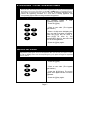
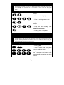
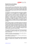
TABLE OF CONTENTS
•
Glossary of terms.................................................................... 2
•
Understanding the Code pad lights ........................................ 3
•
Code pad tones ..................................................................... 3
•
Code Pad Diagram ................................................................. 4
•
Fully arming the system – ON MODE .................................... 5
•
Fully arming the system - Quick Arm MODE ........................ 5
•
Partially arming the system – Home MODE........................... 6
•
Disarming – from the On or Home MODE ............................. 6
•
Bypassing – a zone from being armed................................... 7
•
Group bypass.......................................................................... 7
•
Changing / adding user codes................................................ 8
•
Walk test ................................................................................. 8
•
Assigning user code master code functions........................... 9
•
Setting the door chime............................................................ 9
•
Viewing alarm memory ........................................................... 10
•
Reset latched alarms .............................................................. 10
•
Set code pad tones................................................................. 11
•
Set code pad back light level.................................................. 11
•
Change area view................................................................... 12
•
Communicator and siren test.................................................. 12
•
Service light ............................................................................ 13
•
Zone List ................................................................................. 14
•
Installation company details ................................................... 14
GLOSSARY OF TERMS
Abort Delay: An option that allows a delay in reporting to the central station.
Authority Level: The level of access an individual has when using an alarm panel.
Central Station: Location where alarm data is sent during an alarm report.
Chime Feature: An option that allows the code pad to sound a ding-dong whenever an
entry/exit door is opened.
Codes: Can be either User Codes (relating to a person) or Function Codes (a toggle switch to
turn specific functions on/off). NOTE: A system may have up to 99 four (4) digit codes or 66 six
(6) digit codes, but not a mixture of the two.
Duress Code: An option that allows a special code to be sent to the central station that
indicates the alarm system is being operated under duress.
Forced Arming: An option that allows the system to be turned on (ARMED) with one or more
zones open. A system that is ready to be “force armed” will flash the ready light. (Note: Those
zones that are not ready will not create an alarm.)
Function Code: A Function Code is either a four (4) or six (6) digit code that has been
programmed by the installer to operate a device.
Group Bypass: An option that allows the user to bypass multiple zones with a single
operation.
Master Code: A master arm/disarm code that can program other user codes.
Multi Area System: A system divided into multiple areas in which its own user or users control
each area.
Perimeter: The outer edge of the protected area.
Quick Arm: An option that allows you to turn on (ARM) the security system by pressing either
the [ON] or [HOME] key on the code pad control (for ARMING only) as programmed by the
installation company.
Home Arm: A mode used to arm the perimeter and unused areas of an occupied premises.
Universal Arming (Uni Arm): When enabled, your alarm system can automatically determine
whether to arm in the Full mode or in the pre-set Home mode by looking to see if you exit your
premises or home inside after arming your system. NOTE: This feature can be used in
conjunction with “Quick Arm”.
User Code: A four (4) or six (6) digit entry used to arm or disarm the system.
Page 2
UNDERSTANDING THE LIGHTS
ON Light
The On light is “on” when the system is armed. The On light is “off” when it is disarmed. The
On light will flash when there has been an alarm during the previous arm cycle.
Power Light
The power light is on if the primary power is on. The power light will flash if the system has a
low battery condition.
Ready Light
The ready light is “on” when the system is ready to arm and “flashes” if ready to force arm. The
ready light is off when the system is not ready to arm because of a zone(s) being faulted.
Home Light
The home light is “on” when the system is armed in the Home Mode. All non bypassed zones
will be delayed and follow the Home delay time. When armed in Home Mode and the On light
will be “on”.
Service Light
The service light is “on” when the is a system fault condition. Refer to the Service menu further
in this Owners Guide for more details.
Zone Light
The zone lights are “off” when everything is normal. A zone light will be “on” if the zone has
been bypassed. If a zone light is “flashing”, that zone is in alarm or has been faulted. If a zone
light is “flashing” rapidly, it means that the zone is in a trouble condition. Trouble conditions are:
Hardwire Zone Tamper, Wireless Zone Tamper, Sensor Low Battery and Sensor Loss of
Supervision
(A combination of Alarm/Fault and Tamper/Trouble will produce a rapid “flashing” light for a
short period of time, followed by a slow “flashing” light.)
CODE PAD CONTROL TONES (BEEPS)
•
•
•
•
•
•
•
•
•
•
•
Beeps for all key presses; Sounds a continuous tone during the entry delay time.
Pulses when a day zone is violated while the system is disarmed.
Pulses when a fire zone has a trouble condition.
Beeps 3 times for trying to arm with the “Ready” light off, if “Force Arming” has not been
selected.
Beeps for 1 second or emits a “ding-dong” sound for the “Chime” feature.
Beeps during an exit delay; beeps rapidly for the last 10 seconds of an exit delay; and
beeps 1 second at the end of the exit delay.
Pulses when the armed status changes and the AC power is off.
Pulses when the armed status changes and any zone(s) is bypassed.
Pulses when the armed status changes and a low battery is detected.
Pulses when the armed status changes and a tamper condition is detected. Beeps to
indicate telephone line cut, if selected.
Pulses when one or more of the following conditions are detected: zone or box tamper,
low battery, AC power fail, or expander trouble.
Entering a valid code will silence the code pad sounder when it is pulsing. Please
contact your installation company if the trouble condition exists.
Page 3
ON KEY
HOME KEY
KEYS 1 & 3
FIRE
KEYS 4 & 6
MEDICAL
EMERGENCY
ACTIVATION KEYS
PRESS AND HOLD
FOR 2 SECONDS
KEYS & #
DURESS
*
Page 4
FULLY ARMING THE SYSTEM – ON
MODE
ON is used when the user is away from the premise and wants the interior protected. Listed
below are the steps to arm in the ON Mode:
1.
2.
Close all protected doors and windows. The Ready light will turn on when all protected zones
and sensors are secure. NOTE: If any zones are bypassed, a sensor in that zone can be
violated without affecting the ready light. The security system will not arm if the ready light is
not on. If the power light is off, you have no AC power. Restore power if possible. If not,
contact your installation company.
Enter your 4 digit user code to arm the system. The armed and exit lights will turn on. You
may now leave the building via the designated exit path.
Note: The exit light will flash rapidly for the last 10 seconds of the exit delay as a warning to
the user that the exit time is about to expire.
Key Sequence
Operation
Example shows a User code of 1234
being used to set the system to the
ON Mode.
FULLY ARMING THE SYSTEM – QUICK
ARM MODE
ON is used when the user is away from the premise and wants the interior protected. Listed
below are the steps to arm in the ON Mode:
1.
2.
Close all protected doors and windows. The Ready light will turn on when all protected zones
and sensors are secure. NOTE: If any zones are bypassed, a sensor in that zone can be
violated without affecting the ready light. The security system will not arm if the ready light is
not on. If the power light is off, you have no AC power. Restore power if possible. If not,
contact your installation company.
The [ON] key to arm the system. The armed and exit lights will turn on. You may now leave
the building via the designated exit path.
Note: The exit light will flash rapidly for the last 10 seconds of the exit delay as a warning to
the user that the exit time is about to expire.
Key Sequence
O
ON
Operation
N
Example shows ON key being used
to set the system to the ON Mode.
Page 5
PARTIALLY ARMING THE SYSTEM – HOME
MODE
HOME is used when the user is inside the premise and wants protection around the
perimeter. Listed below are the steps to arm in the HOME Mode:
1.
2.
Close all protected doors and windows. The Ready light will turn on when all protected zones
and sensors are secure. NOTE: If any zones are bypassed, a sensor in that zone can be
violated without affecting the ready light. The security system will not arm if the ready light is
not on. If the power light is off, you have no AC power. Restore power if possible. If not,
contact your installation company.
Press the [HOME] key. The bypass light will turn on if any zone(s) is bypassed. The light(s)
corresponding to the bypassed zone(s) will turn on, alerting the user that a zone(s) may be
unprotected and can be faulted without an alarm.
Key Sequence
Operation
HOME
Example shows HOME key being
used to set the system to the HOME
Mode.
DISARMING – FROM THE ON OR HOME MODE
When you enter the protected area through one of the designated Entry/Exit doors, the code
pad control will sound a solid continuous tone for the duration of the entry delay time, or until
you enter a valid code. After entering a valid code the red armed light will go off and the tone
will stop. The security system is now DISARMED. If a valid code is not entered before the end
of the entry delay, an alarm will occur. (NOTE: If the red armed light is flashing during the
entry delay, the alarm system has been activated in your absence. Leave the building
immediately and call your installation company and/or the police from a safe location.)
Key Sequence
Operation
Example shows a User code of 1234
being used to Disarm the system
from the ON or HOME Mode.
Page 6
BYPASSING - A ZONE FROM BEING ARMED
If you wish to bypass one or more zones, this must be done while the system is in the
disarmed state. The following steps are used for bypassing zones. Once you have Bypassed
the zone(s) you may Arm the system via the ON or HOME Mode. Any bypassed zone is
automatically un-bypassed when the system is disarmed. To manually un-bypass zones,
perform the bypassing procedure on a zone that is already bypassed. The
corresponding light for that zone will go off when un-bypassed.
Key Sequence
*
0
4
0
5
*
Operation
This example shows
bypassing zones 4 and 5.
1. Press the [*] key.
a
user
2. Enter a user code. (The bypass
light flashes.)
3. Enter a 2-digit zone indicating the
zone you wish to bypass. (Example:
Press the [0]-[4] key for zone 4,
press [0]-[5] for zone 5.) The
corresponding light for that zone will
turn on when bypassed.
4. Press the [*] key again.
GROUP BYPASS
By pressing the [*] key, followed by the [0][0] key, then the [*] key again, all zones that are
designated as group bypass zones will be bypassed. Now you can arm your system in either
the [ON] or [HOME] mode. Once armed pressing the [*] key again will toggle the bypassed
zones on and off.
Key Sequence
*
0
*
Operation
1. Press the [*] key.
0
2. Enter a user code. (The bypass
light flashes.)
3. Press the [0]-[0] keys. The group
bypass zone lights will turn on when
bypassed.
4. Press the [*] key again.
Page 7
CHANGING / ADDING USER CODES
User Codes are 4 digits long and must all be different to each other. A master Code must be
used to Change and Add user codes. The default master code is user code one [01] with a
code of [1234]. Any user code can be assigned as a master code (See User Code
Authorisation). Note the system must be disarmed before user codes can be changed or
added.
Key Sequence
Operation
Example shows user one [01] code
change.
1. Enter function five [*5].
2. Enter an existing master code.
3. Enter the user code to add or
change.
4. Enter the new four-digit user
code. Repeat steps 3 and 4 for
additional user codes.
5. Enter [#] when completed.
WALK TEST
Walk test is used to test the functionality of your entire zones, and should be performed
regularly. When in walk test mode the code chime sounder will sound each time a zone is
activated, while each activated zone will display on the code pad for the duration of the walk
test period. Once you have activated all zones we can exit the walk test mode. During walk
test the system will not report to the control room.
Key Sequence
*
Operation
1. Enter [*] [ON].
ON
1
2
3
4
1
2
3
4
2. Enter a master code. The system
is now in walk test mode.
3. Enter a master code to exit walk
test. If no master code is enter walk
test mode will automatically exit in 15
minutes.
Page 8
ASSIGNING USER CODES (Master Codes)
Any User Code can be assigned a master code so that code can change or add other codes
and have access to other functions available on this system.
Key Sequence
Operation
Example shows user two [02] code
change.
1. Enter function six [*6].
2. Enter an existing master code.
3. Enter the user code to have
changed to a master code.
4. Enter the four-[4] key. Repeat
steps 3 and 4 for additional user
codes.
5. Enter [#] when completed.
SETTING THE DOOR CHIME
The door chime is turned on or off by pressing the [HOME] key while the system is in the
disarmed state. Each press of the [HOME] key will toggle the chime feature on/off and
produce a momentary ding-dong sound.
Key Sequence
*
HOME
Operation
Press the [HOME] key to turn on or
turn off the chime feature.
Page 9
VIEWING ALARM MEMORY
Whenever an alarm activation occurs on you system all zones that were in alarm during that
activation will be held in memory. The last alarm activation can be reviewed via the function
listed below.
Key Sequence
Operation
The ALARM MEMORY feature [*][3]
will flash those zones that created
alarms and will light steady those
zones that were bypassed during the
last alarm.
RESET LATCHED ALARMS
To reset Smoke Detectors, Zone Troubles and Zone Tampers, the Reset Latched Alarms
function must be used. Note: If the code pad begins beeping, the reset did not execute
properly. Enter your code to silence the code pad. Wait a few minutes and repeat the reset
function to attempt another reset. If the code pad still beeps after repeated attempts, please
contact your installation company.
Key Sequence
Operation
1. Enter you code to silence the
code pad sounder.
2.
Page 10
Enter the reset function [*][7].
SET CODE PAD TONES
Each code pad can have its sounder tone frequency adjusted to your individual
requirements. Follow the steps below to adjust the code pad sounder.
Key Sequence
*
1
9
0
Operation
1. Enter [*] [9][0] to start the code
pad tone adjustment. The code pad
sounder will sound at the current set
frequency.
2. Enter the one [1] key to raise the
tone or the two [2] key to lower the
tone.
2
#
3. Enter [#] to exit and save the
selected code pad tone.
SET CODE PAD BACK LIGHT LEVEL
Each code pad can have its back light level adjusted to your individual requirements. Follow the
steps bellow to adjust the code pad back light level.
*
1
2
#
Key Sequence
Operation
9
1. Enter [*] [9][1] to start the code
pad back light adjustment.
1
2. Enter the one [1] key to brighten
the back light or the two [2] key to
dim the back light.
3. Enter [#] to exit and save the
selected code pad back light level.
Page 11
CHANGING AREAS
In a multi-area system it is possible to control more than one area from the one code pad by
switching area views. To change the current code pad area view, follow the key sequence
show below. Note that once an area view is accessed the code pad will revert to the default
area view after 10 seconds unless a key is pressed, in which case it will only switch back 60
seconds from the last key press.
Key Sequence
*
1
1
-
8
Operation
1. Enter [*] [1] to access the change
area function.
2. Enter an area number from 1
through to 8 to select the area to
view.
COMMUNICATOR & SIREN TEST
The system sirens and communicator should be tested regularly. The key sequence below is
used to perform the siren and communicator test.
Key Sequence
Operation
1. Enter keys [*] [4] [4] to initiate the
test option
2. Enter the 4 digit user code to turn
off the sirens.
Page 12
SERVICE LIGHT
The service light will be “on” if the security system requires service. If the service light is
“on”, press the [*] key followed by the [2] key to determine the service condition. One or
more zone lights will turn on indicating what service(s) is required. Call you local Chubb
Service Branch immediately for these problems. Below is a listing of what each light means
in a service condition.
Key Sequence
Operation
1. Enter keys [*] [2] and use the table
below to identify the service condition.
LIGHT
Condition
1
SYSTEM FAULT - Press the [1] key. The zone light(s) that is turned on corresponds to
the system fault(s) below:
1
Over Current Fault
5
Expander Low Battery
2
Siren Trouble
6
Expander Box Tamper
3
Box Tamper
7
Expander Trouble
4
Expander Power
8
Reserved
Note: Faults 1 & 2 are global in nature and will affect all areas of a multi-area system.
Press the [#] key to return to the 1 of 8 service lights.
2
ZONE TAMPER - Press the [2] key and the zone light(s) will turn on showing the zone(s)
that is tampered. Press the [#] key to return to the 1 of 8 service lights.
3
ZONE LOW BATTERY - Press the [3] key. The zone light(s) will turn on showing which
zone(s) has a low battery. This only applies to wireless zones. Press the [#] key to
return to the 1 of 8 service lights.
4
ZONE LOSS OF SUPERVISION - Press the [4] key and the zone light(s) will turn on
showing which zone(s) has loss of supervision. This only applies to wireless zones.
Press [#] key to return to the 1 of 8 service lights.
5
ZONE TROUBLE - Press the [5] key and the zone light(s) will turn on showing which
zone(s) has a trouble condition. Press the [#] key to return to the 1 of 8 service lights.
6
TELEPHONE LINE TROUBLE/LINE CUT - This light will turn on when there is
telephone line trouble or the telephone line has been cut. The service light will remain lit
until the telephone trouble clears and a user code is entered. Note: This fault is global in
nature and will affect all areas of a multi-area system.
7
FAILURE TO COMMUNICATE - This light will turn on when there is a failure to
communicate between your system and the central station. Note: This fault is global in
nature and will affect all areas of a multi-area system.
8
LOSS OF SYSTEM TIME - This light will turn on when there has been a loss of power
and your system clock needs to be reset. Instructions are on page 15. Note: This fault is
global in nature and will affect all areas of a multi-area system.
Exit
To exit the Service Light Mode - press the [#] key.
Page 13
3
4
5
6
7
8
INSTALLATION COMPANY DETAILS
NAME
ADDRESS
CONTACT NAME
PHONE
FAX
EMAIL
NEXT SERVICE
WARRANTY PERIOD
Page 14
24 HOUR
2
HOME
MODE
ENTRY /
EXIT
ZONE LIST
1