1
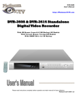
M PEG 4 S TAND-ALONE D VR DVR STAND-ALONE MPEG4 KPD-M Series User’s Manual ■ Some system menu can be different from each model ■ Some system menu is subject to change by firmware upgrade ■ Please read this manual carefully before running DVR system CAUTION TO REDUCE THE RISK OF ELECTRICAL SHOCK, DO NOT OPEN COVERS. NO USER SERVICEABLE PARTS INSIDE. REFER SERVICING TO QUALIFIED SERVICE PERSONNEL. Please beware of the following precautions before installing the DVR. Avoid any place with moisture, dust, or soot. Avoid any place with direct sunlight or heating appliances. Keep the product away from electric shock or magnetic substances. Avoid high or low temperature. (Recommended operation temperature is between 0°C ~ 40°C). Do not place any conductive material through the ventilation. Turn off the system before installation. Ensure enough space for cable connections. Place the system on a solid surface with sufficient air ventilation. Avoid any surface that vibrates. Placing the system near electronic devices such as radio or TV may cause breakdown to the product. Do not disassemble the product without assistance from the manufacturer. Do not place any heavy object on the system. NOTE This equipment had been tested and found to comply with the limits for a CLASS A digital device, pursuant to Part 15 of FCC Rules. These limits are designed to provide reasonable protection against harmful interference when the equipment is operated in a commercial environment. PLEASE READ THIS MANUAL THOROUGHLY FOR EFFECTIVE AND SAFE USAGE OF THE DEVICE. 2 CONTENTS I. KEY FEATURES ------------------------------------------------------------------- 5~6 II. UNIT PACKAGE ------------------------------------------------------------------ 7 III. BUTTON AND CONNECTION ----------------------------------------------- 8~11 IV. REMOTE CONTROLLER ----------------------------------------------------- 12 V. OPERATION ---------------------------------------------------------------------------------------- 13~20 1. POWER ON -------------------------------------------------------------------------------------- 13 2. LOG IN SYSTEM ------------------------------------------------------------------------------- 13 3. RECORD ------------------------------------------------------------------------------------------ 13 4. LIVE MODE -------------------------------------------------------------------------------------- 14~15 5. SEARCH MODE ---------------------------------------------------------------------------- 16~17 6. FUNCTION --------------------------------------------------------------------------------------- 18~20 VI. SYSTEM SETUP ---------------------------------------------------------------------------------- 21~40 THE TABLE OF MENU --------------------------------------------------------------------- 21~22 1. SYSTEM ---------------------------------------------------------------------------------------- 23~26 z 1-1 PASSWORD ------------------------------------------------------------------------------ 23 1-2 TIME -------------------------------------------------------------------------------------- 24~25 1-3 PTZF PROTOCOL -------------------------------------------------------------------------- 25 1-4 STORAGE ------------------------------------------------------------------------------------- 25~26 1-5 CHANGE LANGUAGE ------------------------------------------------------------------- 26 1-6 SOFTWARE UPDATE ------------------------------------------------------------------ 26~27 1-7 SETUP DATA 27~28 ----------------------------------------------------------------------- 2. DISPLAY ------------------------------------------------------------------------------------------ 28~30 2-1 SEQUENCE DWELL (SINGLE) ----------------------------------------------------------- 28 2-2 SEQUENCE DWELL (GROUP) ----------------------------------------------------------- 28 2-3 CAMERA NAME ---------------------------------------------------------------------------- 28 2-4 CAMERA STATUS ------------------------------------------------------------------------- 29 2-5 CAMERA COLOR -------------------------------------------------------------------------- 29 2-6 SPOT DWELL (SINGLE) --------------------------------------------------------------------- 29 2-7 SPOT DWELL (GROUP) -------------------------------------------------------------------- 30 2-8 VGA FREQUENCY CHANGE ------------------------------------------------------------ 30 2-9 VIDEO STANDARD ------------------------------------------------------------------------- 30 3. RECORD -------------------------------------------------------------------------------------------3-1 REC PROPERTY ---------------------------------------------------------------------------- 31~35 31 3-2 REC OPTIONS ------------------------------------------------------------------------------- 31~32 3-3 EVENT REC ----------------------------------------------------------------------------------- 32~34 3 3-4 SCHEDULE REC ---------------------------------------------------------------------------- 34 3-5 DELETE REC --------------------------------------------------------------------------------- 35 3-6 LOCK/UNLOCK ------------------------------------------------------------------------------ 35 3-7 DELETE ALL REC -------------------------------------------------------------------------- 35 4. NETWORK ------------------------------------------------------------------------------------------ 36~38 4-1 NETWORK TYPE ---------------------------------------------------------------------------- 36 4-2 DDNS ------------------------------------------------------------------------------------------- 37 4-3 NET PASSWORD --------------------------------------------------------------------------- 37 4-4 NET CLIENT PORT ------------------------------------------------------------------------- 37 4-5 NET CLIENT ID ------------------------------------------------------------------------------ 38 4-6 NET DVR ID -------------------------------------------------------------------------------------- 38 4-7 NET CLIENT ADDR ------------------------------------------------------------------------- 38 4-8 NETWORK THROUGHPUT -------------------------------------------------------------- 38 4-9 WEB PORT --------------------------------------------------------------------------------5. SENSOR / AUDIO -------------------------------------------------------------------------------- 39~40 5-1 SENSOR TYPE ------------------------------------------------------------------------------ 39 5-2 ALARM MOTION MANAGER ------------------------------------------------------------ 39 5-3 ALARM SENSOR MANAGER ----------------------------------------------------------- 39 5-4 ALARM BUZZER ---------------------------------------------------------------------------- 40 5-5 ALARM OUTPUT ---------------------------------------------------------------------------- 40 5-6 ALARM OUT PERIOD ---------------------------------------------------------------------- 40 5-7 AUDIO ------------------------------------------------------------------------------------------ 40 * HDD INSTALLATION ------------------------------------------------------------------------------- 41 * TROUBLE SHOOTING ------------------------------------------------------------------------------- 42 4 KEY FEATURES Operation Embedded LINUX OS Enhanced MPEG4 compression Display, Playback, Recording, Network transmission Real time single or multi-screen display Easy operation by IR remote controller Hidden camera option (covert) Easy firmware update by network and USB 2.0 Playback Multi-screen playback Search by time, event and calendar with go first/last function Simple playback – automatic download of viewer software at backup Recording Recording resolution and quality level adjustable Recording frame rate can be set by user The recording speed of max. 120/100 images per second (NTSC/PAL) Continuous, manual, schedule and event (motion, alarm) recording Pre-alarm/post alarm recording Delete and lock/unlock recording video available 4 channel audio recording Alarm pop-up Event log view Network Live, playback with viewer software and IE(Internet Explorer) Remote control via networked PC with the exclusive client viewer Supporting Static, DHCP, DDNS, PPPoE Multi-user connection available Live and Recording audio File play in network 5 KEY FEATURES Audio 4 channel audio recording in real time 1 channel audio output Backup Remote backup on network PC with the exclusive client viewer CD-RW (DVD-RW) backup USB 2.0 backup( Both USB stick and USB connection HDD available) General Auto detection of video frequency(NTSC/PAL) Built-in hardware Watchdog S-Video output Alarm In/Out, RS-485, RS-232 Connections Loop-through connections Multiple Languages VGA output for PC monitor 6 UNIT PACKAGE MPEG4 DVR System Viewer Program/Manual Install Guide LAN cable Battery Remote controller Power cord HDD screws DC adaptor (DC12V 5A) 7 BUTTON AND CONNECTION 1-1 FRONT PANEL 2 3 4 5 6 7 8 9 16 10 11 12 15 1 14 1. Channel Selection You select a channel as full-size screen during live display or playback. When the number is above 10, please press the ‘+10’ button at first and press other number. 2. USB 2.0 slot It is used when you upgrade firmware update and backup video files. 3. MULTI When you press the button repeatedly, you can change the screen display mode as you want from PIP to multi channel to single channel view. 4. AUTO The function allows users to watch individual channels by rotating every channel in turn automatically. Please press the button again to stop it 5. PIP (Picture in Picture) If you press the button, you can see a master channel and a slave channel on the master simultaneously. Press the button again, and master becomes slave and vise versa. 6. MUTE You can turn off the audio. 7. INFO INFO key shows system information of DVR only in live display mode. 8. OSD If you do not need OSD, press the button. Pressing one more time retrieve the OSD. 9. BACKUP You can backup video in CD-RW (DVD-RW) or USB (Memory stick and exterior HDD) in playback mode. 10. LED Lights You can identify how power, record, HDD and network(NET) are. 11. MENU You can change DVR settings. When you want to return to the previous step, press the button again. 8 13 BUTTON AND CONNECTION 12. SEARCH You can choose the video file you want to find through this key. 13. REC You can manually record by pressing the button. Press it once more, and you can stop recording. 14. Playback REW (◀◀): Rewind the video (up to 128x) PLAY/PAUSE (▶/II): Play and Pause the video FAST (▶▶): Fast forward the video (up to 128) STOP (■): Stop the video. 15. PTZ When you want to control speed dome cameras, please press the button. 16. Control keys You can shift up, down, right and left and select what you want to. 9 BUTTON AND CONNECTION 1-2 REAR PANEL 1 2 3 4 KPD-M1601 14 13 12 11 10 9 8 7 KPD-M901 KPD-M401 1. Audio In RCA 4 channel audio inputs 2. Video Input Max 16 channel video inputs 3. Loop out Max 16 channel video loop outputs 4. Power switch 5. Power Input Input: 100V~240VAC 50/60Hz 1.5A Output: DC 12V, 5A 6. SEN. IN/AL/485 Sensor In:16Ch(1~16), 9Ch(1~9), 4Ch(1~4) 17-20: Alarm Out, 21: 485+, 22: 485-, 23-25: GND 10 6 5 BUTTON AND CONNECTION 7. RS232 Connection port for engineering use only 8. VGA VGA output connecting to LCD monitor 9. USB USB 2.0 for system update and video backup 10. LAN LAN connecting to a variety of networks 11. Audio Out RCA 1 channel audio output 12. S-Video Connecting to S-Video monitor 13. Video Out Connecting to monitor KPD-M401: 2 outputs, KPD-M901/1601: 1 output 14. Spot Out (*KPD-M901/1601) Connecting to spot monitor 11 HDD INSTALLATION 1 2 1. REC (Record) 3 2. Channel Selection You select a channel as full-size screen during live display or playback. When the number is above 10, please press the ‘+10’ button at first and press other number. 7 4 3. REC STOP: Record stop button 5 6 8 9 4. INFO: DVR Information 10 12 5. P/T: Pan, Tilt 11 6. Z/F: Zoom, Focus 13 7. OSD: OSD on/off 8. MENU 14 9. LOG: Log list view 19 10. SEARCH 11. Direction keys(▲, ▼, ◀, ▶) 15 16 17 18 : Move cursor or control PTZF Camera 12. MUTE 13. BACKUP 14. Playback control keys 15. SPOT 16. PIP 17. POP 18. AUTO 19. Multi display modes 12 HDD INSTALLATION 1. Power on Press power button on rear of the unit. If system begins, loading message will appear. (It takes around 30seconds to boot DVR system) 2. Log in system Enter your password (Default : 0000) to Login the system a. To change your password, please refer Page 23. b. Administration password pops up when users press MENU button. ENTER PASSWORD ---- ENTER ADMIN PASSWORD ---- 3. Record Press REC button to record the video. If you press REC button once more, recording will be stopped. BEFORE RECORDING, PLEASE CHECK!! ,,,(1) Check out whether the date and time are ,,,,,correctly set. ,,,(2) Check out whether HDD is formatted. ,,,,,,,,,If HDD is not formatted, please format HDD. ,,,,,,,,,Æ Please refer Page 27 to format HDD ,,,(3) Make sure that each camera screen displays ,,,,,properly. ,,,(4) Set up the camera channel name. ,,,(5) Select recording quality. ,,,(6) Select recording method. ,,,(7) Recording can be stopped by pressing REC ,,,,,,,,button again. To keep recording, we recommend ,,,,,,,,you to set recording mode in “CONTINUOUS”. 13 HDD INSTALLATION ,,,,,,,Æ Please refer Page 31. 4. Live mode Date / Time 4.1 Display on screen Current mode 2006/09/25-11:11:25 LIVE : Live video PLAY : Playback USB : USB equipment is connected REC : Recording >> : Fast forward Speed rate on playback << : Fast rewind Speed rate on playback LIVE HDD status MA-A:99% SL1-B:NONE 4.2 Display of full screen mode Camera status 1 : Camera No. R : Record M : Motion S : Sensor HDD status Current mode LIVE 1RMS MA-A:90% SL1-B:NONE LIVE : Live video PLAY : Playback REC : Recording >> : Fast forward Speed rate on playback << : Fast reward Date / Time Speed rate on playback 2006/02/01-12:00:07 4-3. Quad screen (*Remote control) To see quad screen when the full screen mode, press 4-4. Full screen (*Remote control) To see specific camera by full screen, press button. button * KPD-M901 / M1601 4-5. 9ch display mode (*Remote control) To see cameras by 9ch mode, press button * KPD-M1601 4-6. 16ch display mode (*Remote control) To see camera by 16ch mode, press button * KPD-M901 / M1601 4-7. POP mode (*Remote control) Press POP button to enlarge specific camera. Whenever pressing POP button, go to next camera. POP 4-8. Auto Sequence (Auto) Interval display on the monitor before going to the next channel. the default time span from one channel to another is 2 seconds. User can select the range of time from 1 to 60 seconds. 14 HDD INSTALLATION If you want to change interval time to rotate the camera, please go to ‘MENU’ and setup the interval time. 4-9. PIP When it is in full screen display mode, you can see other camera in a small window. (1) Press PIP button of remote controller to go to PIP mode (2) If you press this button in PIP mode, the position of two cameras will be swapped. 1 2 ‘PIP’ Button 2 1 (3) Press Camera button in PIP mode to change small screen to another camera. Example) 1 1 Cam ‘3’ Button 2 3 (4) Press Direction button to move small window at appropriate position. 15 HDD INSTALLATION 5. Search mode (1) Press Search button (2) Select Search method by using ▲▼ button and press ‘ENTER’ button Search data by Year /Month/Day/Time TIME SEARCH [SEARCH] Search only Data recorded by motion EVENT SEARCH detection function * TIME SEARCH CALENDAR SEARCH Search data in calendar * EVENT SEARCH Search from the top of the list GO FIRST * CALENDAR SEARCH * GO FIRST Search from the bottom of the list GO LAST * GO LAST 5-1. TIME SEARCH [TIME-SEARCH] YEAR : 0000 MONTH : 00 DAY : 00 TIME : 00:00 (1) If you select TIME SEARCH, Time Search table will appear (2) Key in the year, month, day and time that you want to search for. (3) Press the Enter key. 5-2. EVENT SEARCH (1) If you select EVENT SEARCH, the calendar will appear. (2) Select desired date by using ◀▶▲▼ button and press ‘ENTER’ button [CALENDAR-EVENT SEARCH] EVENT LIST 1/2 0013 060910:230233 FL MD 01 08 09 0012 060910:225033 FL MD 01 07 09 0011 060910:224233 FL MD 01 08 09 0010 060910:223233 FL MD 01 08 16 0009 060910:215233 FL MD 01 08 09 0008 060910:213233 FL MD 01 08 09 0007 060910:210233 FL MD 01 08 09 PGDN:< PGUP:> LAST:<< FIRST:>> <<2006-09>> SUN MON TUE WED THU FR I SAT 1 2 3 4 5 6 7 8 9 10 11 12 13 14 15 16 17 18 19 20 21 22 23 24 25 26 27 28 29 30 (3) Select desire video clip in the list by using ▲▼ button and press ‘ENTER’ button. * The specifications of Event list Date / Time MD : Motion detection SD : Sensor detection EVENT LIST 00078 PGDN:< File 1/7 20050705:121000 FL MD 01 02 03 04 L PGUP:> LAST : << Lock/Unlock Current page / Total pages FIRST:>> Recorded camera No 16 HDD INSTALLATION 5-3. CALENDAR SEARCH (1) If you select CALENDAR SEARCH, the calendar will appear. (2) Select desired date by using ◀▶▲▼ button and press ‘ENTER’ button (3) Select hour and minute that you want to search. The hour bar is divided into 24 sectors (unit of one hour), and the minute bar is done into 30 sectors (unit of two minutes). [SEARCH-TIME] <<2006-09>> SUN MON TUE WED THU FR I SAT 1 2 3 4 5 6 7 8 9 10 11 12 13 14 15 16 17 18 19 20 21 22 23 24 25 26 27 28 29 30 HOUR: MIN: TIME : 00:00:00 5-4. GO FIRST (1) If you select GO FIRST, you can play back from the top file of the list to bottom. 5-5. GO LAST (1) If you select GO LAST, you can play back from the bottom of the list. 5-6. Playback If you press Play button in live mode, the video clip recorded recently will be played. If you want to see specific camera by full screen, press camera button. For display of quad mode from full screen, press quad button. You can control playback speed with ◀◀ / ▶▶ button. Once you press the - X2, X4, X8, X16, X32, X64, X128 REWIND / Frame - Reduce Fast Forward speed while Fast Forward play ◀◀ by frame - Reverse playback frame by frame during PAUSE mode PLAY / PAUSE Play the video and pause the video ▶I - X2, X4, X8, X16, X32, X64, X128 FAST FORWARD ▶▶ - Reduce Fast Reward speed while Fast Rewind / Frame by frame - Forward play frame by frame during PAUSE mode STOP Stop the playback and go to Live mode ■ 17 HDD INSTALLATION 6. Function 6-1. INFO Show the present status of DVR system If you press direction button (▶), detailed information is shown. (Normal informationÆ REC information Æ S/W informationÆ HDD information) [STATUS] S/W VERSION S/W VERSION : VO.9.0-BY-16 (07/11/05 20:40) [HDD] MA:75G ( 10%) SL1: NONE SL2:36G(0%) SL3: NONE NETWORK : STATIC 192.168.1.200 MAC : 00.0E.B5.00.0C.B6 DDNS : DDNS OFF WEB PORT : 80 NEXT INFO : RIGHT KEY Software version HDD Indicate each HDD capacity and Used capacity NETWORK Indicate the information of Static or Dynamic IP address MAC Indicate DVR own MAC address DDNS Indicate service the statue of DDNS [REC] SIZE [REC] SIZE : 360X240 CH RATE QUALITY CH RATE QUALITY 1 30 NORM 9 30 NORM 2 30 NORM 10 30 NORM 3 30 NORM 11 30 NORM 4 30 NORM 12 30 NORM 5 30 NORM 13 30 NORM 6 30 NORM 14 30 NORM 7 30 NORM 15 30 NORM 8 30 NORM 16 30 NORM CH RATE QUALITY KERNEL : Unknown BOOT LOADER : Unknown ENC. FIRMWARE : 20051031_0 DEC. FIRMWARE : 20051031_0 APPLICATION : 1.0.7 UI VER : 1.0.5-F16 DECODER VER : 1.4.0-0 ENCODER VER : 1.0.2-1 NETWORK VER : 1.0.5-3 DB VER : 1.0.1-3 MA : 20050412_084000_nCw.ps 20050427_162000_pCw.ps SL1 : HARD DISK NOT EXIST SL2 : CD-ROM SL3 : HARD DISK NOT EXIST 18 Recording resolution Camera No. Statue of frame rate for recording Indicate recording quality (BEST/HIGH/NORMAL/BASIC) HDD INSTALLATION 6-2. MUTE When you press MUTE key, AUDIO setup window appears. Press the enter key when you set mute mode or Audio on. FYI, Audio works only full screen mode. [AUDIO] STATUS : ▷ MUTE 6-3. BACKUP User can backup the data to USB stick (USB HDD) or built-in CD (DVD)-RW. (1) Connect USB equipment to USB port of DVR system. (2) Press ‘BACKUP’ button. (3) Select a method and press ‘ENTER’ button. CD-R CD-RW DVD-R DVD-RW USB MEMORY ① Select device to backup FILE FORMAT NATIVE ② Select backup file BACKUP BASE FILE TIME ③ Select backup type CAMERA ALL [.]1~[.]16 ④ Select camera to backup [BACKUP] MEDIA TYPE : ▷ CD-R FILE FORMAT : ▷ NATIVE BACKUP BASE : ▷ FILE CHANNEL : ▷ ALL [*] 1 [*] 2 [*] 3 [*] 4 [*] 5 [*] 6 [*] 7 [*] 8 [*] 9 [*] 10 [*] 11 [*] 12 [*] 13 [*] 14 [*] 15 [*] 16 START : END : TOTAL SIZE : 0M MEDIA TYPE BACKUP ⑧ Select BACKUP and press ‘ENTER’ button ⑨ In case of CD/DVD-RW, you can erase data in media by FORMAT MEDIA. FORMAT MEDIA START END TOTAL SIZE ⑤ Start time to backup file ⑥ End time to backup file ⑦ Indicate total size to backup 6-4. PTZ (Pan / Tilt ) Press the PTZ button. Users can control PAN/TILT camera by direction button. PTZF << CH: 01 >> << PAN :>> << TILT :>> << ZOOM >> << FOCUS>> CH: 01 Press direction button to set the PTZ camera channel. PAN Press direction button to move camera up and down. TILT Press direction button to move camera right and left. ZOOM Press direction button to zoom in and out. FOCUS Press direction button to focus the video images. 19 HDD INSTALLATION 6-5. LOG LIST (*Remote controller only) Show all information about what happened to DVR system during operation. [EVENT LOG VIEW] EVENT TYPE : ALL MOTION : [.] SENSOR: [.] ALARM : [.] V-LOSS : [.] SYSTEM: [.] HDD : [.] FILE : [.] DB : [.] POWER : [.] NET : [.] FROM: 2005-11-05 00:00 TO: 2005-11-05 23:59 OK CANCEL ① Select Log view type and press ‘ENTER’ button ALL Show all information EVENT TYPE PART Show desired information ② Select desired sub-items and press ‘ENTER’ button when you choose “PART”. ③ Input desired start time FROM ④ Input desired end time TO ⑤ Select OK and press ‘ENTER’ button * Example of Log list 1234 No. Event MD SD VL SY FL PW NT HD DB 060123:095436 MD Event date / time Event. Meaning Motion Detection Sensor Detection Video Loss System File Power Network Hard Disk Data Base OOOOOOOOOOOO Detailed information Description Detect motion Detect sensor No video Change system setup Delete or Create a file Power On / Off Access system by network Information of HDD Information of data base 20 OPERATION Tips for setup of DVR system (1) (2) (3) (4) (5) (6) (7) Press ‘MENU’ button to setup DVR system. The window for password input will appear. Enter your Password. (Default : 0000) Select desired sub-menu item with Direction button. Press ‘ENTER’ button to go to submenu or save system. Press ‘MENU’ button to go to previous mode without save or escape system menu. How to use text input dialog box when you need to input a text to system 1) When text input dialog box appears, select [TEXT INPUT DIALOG] desired alphabet and mark by Direction button. ABCDEFGH I J 2) Press ‘ENTER’ button to input text. KLMNOPQRST 3) Then, the selected text will appear. 4) Press ‘MENU’ button to quit dialog box. UVWXYZ ← a b c d e f g h I j k l mn o pq r s t u v wx y z .~ / : 0123456789 _ - @ SPACE CH 01 -------------------------- The Table of MENU MENU SUB MENU 1-1.PASSWORD 1-2.TIME 1. SYSTEM 2. DISPLAY DESCRIPTION 1-1-1.ADMIN PASSWORD Change system password for administrator 1-1-2.USER PASSWORD Change system password for user 1-1-3.PASSWORD CHECK Activate system password 1-2-1.TIME SETUP Setup current time 1-2-2.TIME FORMAT Setup time format 1-2-3.TIME OSD FORMAT Set TIME OSD color and position on screen 1-3.PTZF PROTOCOL Set PTZF cameras 1-4.STORAGE Format HDD / Overwrite setting 1-5.CHANGE LANGUAGE Change Language of Menu 1-6.SOFTWARE UPDATE Upgrade System Software 1-7. DEFAULT SETUP Set the system as to factoring default 2-1.SEQUENCE DWELL(SINGLE) Set switching time interval on Live full display 2-2.SEQUENCE DWELL(GROUP) * 9/16ch Set switching time interval on Live quad display 2-3.CAMERA NAME Input Camera name 2-4.CAMERA STATUS Show or Hide a specific camera 2-5.CAMERA COLOR Control the color of camera 2-6.SPOT DWELL (SINGLE) * 9/16ch Set switching time interval on full display of Spot 21 OPERATION 3. REC 4. NETWORK 5. SENSOR / SOUND 2-7.SPOT DWELL (GROUP) * 9/16ch Set switching time interval on quad display of Spot 2-8.VGA FREQUENCY CHANGE Change VGA frequency 2-9.VIDEO STANDARD Set the video standard 3-1.REC PROPERTY Set recording property (Resolution/Quality/Frame rate) 3-2.REC OPTIONS Set recording option (Continuous / DEINTERLACE / Water mark ) 3-3.EVENT REC Set Motion / Sensor 3-4.SCHEDULE REC Set schedule recording 3-5.DELETE REC Delete record file 3-6.LOCK/UNLOCK REC Protect specific file from delete 3-7.DELETE ALL REC Delete all files 4-1.NETWORK TYPE Set the present network system (Static / Dynamic) 4-2.DDNS Set network for DDNS 4-3.NET PASSWORD Assign password to access the DVR system by Net-client software 4-4.NET CLIENT PORT Assign port for port-forwarding in user’s router 4-5.NET CLIENT ID Assign additional ID and password to access the DVR system by Net-client software 4-6.NET DVR ID For system check of net client when network connection 4-7.NET CLIENT ADDR Limit Client IP address to access DVR system * With only registered IP address, allow user to access DVR system 4-8.NETWORK THROUGHPUT Set the speed of data transmission in DVR system 5-1.SENSOR TYPE Set present network system (Static / Dynamic) 5-2.ALARM MOTION MANAGER Set Alarm output when motion is detected 5-3.ALARM SENSOR MANAGER Set Alarm output when sensor is detected 5-4.ALARM BUZZER Set Alarm buzzer ON/OFF 5-5.ALARM OUTPUT Set Alarm output ON/OFF to each camera 5-6.ALARM OUT PERIOD Set working time of Alarm output 5-7.AUDIO Set audio on designated channel 22 OPERATION 1. SYSTEM 1-1. PASSWORD 1-1-1 . ADMIN PASSWORD Admin password is for administrator. With this password, user can access to all menus of system. Password consists of only four digit numbers. (1) Enter new Password to change by using Number button. (2) Enter new Password again to confirm the Password. [ADMIN PASSWORD] CONFIRM NEW ADMIN PASSWORD :____ [ADMIN PASSWORD] ENTER NEW ADMIN PASSWORD ____ 1-1-2. USER PASSWORD (1) Enter new Password to change by using Number button. (2) Enter new Password again to confirm the Password. [USER PASSWORD] CONFIRM NEW ADMIN PASSWORD :____ [USER PASSWORD] ENTER NEW ADMIN PASSWORD ____ 1-1-3. PASSWORD CHECK (1) Select desire sub-menu to setup by using ▲▼ button and press ‘ENTER’ button ADMIN : Access all system [CHECK PASSWORD] USER : Only for logging on system ADMIN : ON USER (2) Select OFF or ON ON : can access the system after confirmation of Password OFF : can access the system without Password input : ON [CHECK PASSWORD] - OFF - ON (3) Press ‘MENU’ button to go to previous mode. In case you forgot the passwords, please press the keys in the remote controller. INFO->MUTE->SEARCH->■-> When you press the keys in turn, you can see ‘Factory Setup’ mode to reset the password again. If the reset password works correctly, you have to set the DVR into the factory default in System menu. 23 OPERATION 1-2. TIME 1-2-1. TIME SETUP (1) Select desired sub-menu by direction button and enter Year / Month / Day / Time by using Number button. (2) New window will appear. Press ‘ENTER’ button to change time. If you really want to change, press Yes, otherwise No. WARNING!!! TIME SETUP TIME WILL BE CHANGED THE FILES AFTER CHAHGED TIME WILL BE DELETED YEAR : 0000 MONTH : 00 DAY : 00 TIME : 00:00 Are you sure? [ENTER] Æ YES, [MENU]Æ NO If you change the date/time to previous date/time, previous recorded data can be deleted as follows. So, strongly recommended to backup data before changing time. Changed new date/time previous date/time DATA FILE This part of data file will be deleted 1-2-2. TIME FORMAT (1) Select desire TIME format by direction button and press ‘ENTER’ button. If the date is Dec 30th 2006 [TIME FORMAT] - YY / MM / DD - DD / MM / YY - MM / DD / YY FORMAT DISPLAY YY/MM/DD 2006/12/30 DD/MM/YY 30/12/2006 MM/DD/YY 12/30/2006 <Format description> 24 OPERATION 1-2-3. TIME OSD FORMAT (1) Select desire position and color of time format and press ‘ENTER’ button. TOP-WHITE [TIME OSD FORMAT] TOP-WHITE TOP-BLACK BOTTOM-WHITE BOTTOM-BLACK OFF TOP-BLACK 2005/06/20 12:30:05 2005/06/20 12:30:05 OFF 2005/06/20 12:30:05 2005/06/20 12:30:05 2005/06/20 2005/06/20 BOTTOM-BLACK BOTTOM-WHITE 1-3. PTZF PROTOCOL (1) In PTZF protocol menu, select sub-item of desire camera and press ‘ENTER’ button to set CH 01 02 03 04 05 06 ID ▷000 ▷000 ▷000 ▷000 ▷000 ▷000 [PTZF PROTOCOL] PROTOCOL BAUD ▷PELCO_D ▷2400 ▷PELCO_D ▷2400 ▷PELCO_D ▷2400 ▷PELCO_D ▷2400 ▷PELCO_D ▷2400 ▷PELCO_D ▷2400 SPEED ▷9 ▷9 ▷9 ▷9 ▷9 ▷9 (2) ID : Enter PTZF camera ID (From 000 to 255) (3) PROTOCOL : Select appropriate protocol. * Available protocol: Pelco D, Pelco P, Chubb i SD, COP, LILIN, CYNIX, DSC230… (4) BAUD : Select appropriate BAUD rate (5) SPEED : Select desire speed for Pan tilt camera (6) Press ‘MENU’ button to finish the setting 1-4. STORAGE 1-4-1. OVER WRITE [STORAGE] OVER WRITE : ▷ YES HDD-A : FORMAT HDD-B : NONE HDD-C : NONE HDD-D : NONE OVER WRITE - NO - YES 25 Select YES or NO (When you choose YES, new video files can be overwritten on recorded ones.) OPERATION 1-4-2. FORMAT When you install HDD in DVR system, you need to format HDD. Make sure that Format function will erase all data file in HDD, which is an unrecoverable command. Completing the formatting, the message (“DISK FORMAT COMPLETE”) will appear. Press the MENU button, and it returns to STORAGE window. If there’s more HDD to format, you can format them again. If not, press MENU button. DVR will reboot automatically. WARNING!!! HDD-A WILL BE FORMATTED ARE YOUR SURE? [‘ENTER’] ->YES PROGRESS FORMAT Yes 55% [‘MENU’]->NO When the HDD detection status is “N/F”, recording function doesn’t work. You have to format the HDD in N/F before recording. 1-5. CHANGE LANGUAGE (1) Press ‘ENTER’ button “Change Language”. (2) Select desired language and press ‘ENTER’ button. [CHANGE LANGUAGE] ENGLISH PORTUGUESE RUSSIAN 1-6. SOFTWARE UPDATE There are two methods to upgrade the DVR system. USB UPDATE : Upgrade the DVR system by using USB memory stick. NETWORK UPDATE : Upgrade the DVR system through Internet After software update, user must turn DVR into Default values in SYSTEM. 1-6-1. USB UPDATE [SOFTWARE UPDATE-USB] WARING Firmware update will start !!! Make sure the new firmware is in USB device. Don’t power off during firmware update [ENTER] ->YES , [MENU]->NO [SOFTWARE UPDATE] - NETWORK UPDATE - USB UPDATE (1) Copy provided Firmware file to your USB memory stick The firmware file should be in Root directory of USB memory 26 OPERATION (2) Connect USB memory stick to USB port in unit. (3) Press ‘MENU’ button and go to Software Update (4) Select USB UPDATE and press ‘ENTER’ button to proceed with software upgrade. (5) After completing upgrade, the system will reboot automatically. (6) Then, Check S/W version through INFO menu. 1-6-2. NETWORK UPDATE [SOFTWARE UPDATE] - NETWORK UPDATE - USB UPDATE [SOFTWARE UPDATE-NETWORK] SERVER IP : videonetserver.com FILE NAME : kpro-16.tar.gz UPDATE CANCEL (1) Check the unit is connected to the Internet. (2) Press ‘MENU button’ and go to Software Update. (3) Check Server IP and File name whether it is correct to download. If it is wrong, select Server IP and File name and press ‘ENTER’ button to input new information by Text input Dialog box. Make sure the information of Server IP & File name through your supplier. (4) Select ‘UPDATE’ and press ‘ENTER’ button to proceed with Software upgrade. (5) After completing upgrade, the system will reboot automatically. (6) Then, Check S/W version by press INFO button 1-7. SETUP DATA KPD-M series supply users with another convenient function. In case users have to setup the menus of several DVR in the same modes, SETUP DATA function reduce the repeated labor by backing up and restoring the menu setup through USB. BACKUP SETUP DATA 1-7-1. BACKUP SETUP DATA Users can backup the current menu setup for Connect USB-Memory and Press ENTER to continue [ENTER]->YES, [MENU]->NO the other DVR menu setup. RESTORE SETUP DATA 1-7-2. RESTORE SETUP DATA Users can restore the backed-up menu setup for Connect USB-Memory and Press ENTER to continue [ENTER]->YES, [MENU]->NO the other DVR menu setup. [DEFAULT SETUP] WARNING Are You Sure? [‘ENTER’] ->YES , [‘MENU’]->NO 1-7-3. DEFAULT SETUP 27 OPERATION Press ‘ENTER’ button to initialize the system in default setup mode. 2. DISPLAY 2-1. SEQUENCE DWELL(SINGLE) (1) In Sequence dwell menu, select desired [S.DWELL(SINGLE)] SEC CH SEC ▷02 09 ▷02 ▷02 10 ▷02 ……… ………. ……… ………. 04 ▷02 16 ▷02 CH 01 02 Camera by using ▲▼ button and press ENTER button. (2) Input desired second by using number button and press ‘ENTER’ button to finish the setting. Maximum time is up to 60 seconds. If you want to cancel, press ‘MENU’ button. 2-2. SEQUENCE DWELL(GROUP) * KPD-M901 / M1601 (1) In Sequence dwell menu, select desired quad no. by using ▲▼ button and press ‘ENTER’ button. [S.DWELL(GROUP)] NO SEC 01 ▷03 02 ▷03 03 ▷03 04 ▷03 (2) Input desired second by using number button and press ‘ENTER’ button to finish the setting. Can enter maximum up to 60 seconds If you want to cancel, press ‘MENU’ button. Group No. Camera Group No. 1 Channel 1 ~ Channel 4 1 Channel 1 ~ Channel 4 2 Channel 5 ~ Channel 8 2 Channel 5 ~ Channel 8 3 Channel 6 ~ Channel 9 3 Channel 9 ~ Channel 12 4 Channel 13~ Channel 16 [KPD-M901] Camera [KPD-M1601] 2-3. CAMERA NAME (1) Select desired camera by using ▲▼ button and press ‘ENTER’ button. (2) TEXT INPUT DIALOG window will appear. (3) Enter desired camera name and press ‘MENU’ button to finish input 28 [CAMERA NAME] NO NAME NO NAME 01 CH 01 09 CH 09 02 CH 02 10 CH 10 03 CH 03 11 CH 11 ........ ……. ……. ……. 08 CH 08 16 CH 16 OPERATION 2-4. CAMERA STATUS (1) Select the camera and press ‘ENTER’ button in Camera status mode. (2) Select desire sub-item and press ‘ENTER’ button. SHOW : Display the camera on monitor HIDE : Not display the camera on monitor [CAMERA STATUS] STATUS ▷SHOW 09 ▷SHOW ▷SHOW 10 ▷SHOW ▷SHOW 11 ▷SHOW ▷SHOW 12 ▷SHOW ……. …….. ……. …….. 08 ▷SHOW 16 ▷SHOW NO 01 02 03 04 Even if a camera is set in hide mode, the camera actually is recorded. Hidden camera won’t be displayed on playback mode also. [STATUS] SHOW HIDE 2-5. CAMERA COLOR (1) Select a desired camera by direction button and press ‘ENTER’ button (2) Select desired item and Press ◀▶ button to ‘ENTER’ the value. ◀ button :- (decrease value): -125 ▶ button : + (increase value) : -125 CHANNEL 1 BRIGHT : 0 CONTRAST : 0 COLOR : 0 DEFAULT -:< +:> (3) Press ‘ENTER’ button to finish the setting. (‘MENU’ button : Cancel the setting) [CAMERA COLOR] CH COLOR CH COLOR 01 ▷DEFAULT 09 ▷DEFAULT 02 ▷DEFAULT 10 ▷DEFAULT 03 ▷DEFAULT 11 ▷DEFAULT [CAMERA COLOR] CH COLOR CH COLOR 01 ▷ADJUST 09 ▷DEFAULT 02 ▷DEFAULT 10 ▷DEFAULT 03 ▷DEFAULT 11 ▷DEFAULT 08 ▷DEFAULT 16 ▷DEFAULT 08 ▷DEFAULT 16 ▷DEFAULT 2-6. SPOT DWELL(SINGLE) * KPD-M901 / M1601 (1) Select desired Camera by using ▲▼ button and press ENTER button. (2) Input desired second by using number button and press ‘ENTER’ button to finish the setting. [SPOT DWELL (SINGLE)] CH SEC CH SEC 01 ▷02 09 ▷02 02 ▷02 10 ▷02 ……… ………. ……… ………. 04 ▷02 16 ▷02 Can enter maximum up to 60 seconds. If you want to cancel, press ‘MENU’ button. 29 OPERATION 2-7. SPOT DWELL(GROUP) * KPD-M901 / M1601 (1) Select desired Camera by using ▲▼ button and press ‘ENTER’ button. (2) Input desired second by using number button and press ‘ENTER’ button to finish the setting. Can enter maximum up to 60 seconds If you want to cancel, press ‘MENU’ button. [SPOT.DWELL(GROUP)] NO SEC 01 ▷02 02 ▷02 03 ▷02 04 ▷02 Group No. Camera Group No. 1 Channel 1 ~ Channel 4 1 Channel 1 ~ Channel 4 2 Channel 5 ~ Channel 8 2 Channel 5 ~ Channel 8 3 Channel 6 ~ Channel 9 3 Channel 9 ~ Channel 12 4 Channel 13~ Channel 16 [KPD-M901] Camera [KPD-M1601] 2-8. VGA FREQUENCY CHANGE (1) Press ‘ENTER’ button in Change VGA freq. (2) Select desired video frequency. [CHANGE VGA FREQ] - 60HZ [CHANGE VGA FREQ] - 60HZ - 50HZ 2-9. VIDEO STANDARD (1) Select your video system AUTO DETECTION : Set video automatically. SWITCH : Set video according to jumper on main board. NTSC : Set video to NTSC system. [VIDEO STANDARD] ▷AUTO DETECTION ▷SWITCH ▷NTSC ▷PAL PAL : Set video to PAL system. After changing Video standard, DVR system will reboot automatically 30 OPERATION 3. REC 3-1. REC PROPERTY. Select desired item and press ‘ENTER’ button to change value. [SETUP-REC-PROPERTY] REC RESOLUTION : ▷ 720X480 CH 01 02 03 08 QUALITY ▷ HIGH ▷ HIGH ▷ HIGH ……. ▷- HIGH RATE ▷ 2 ▷ 2 ▷ 2 CH 09 10 11 ▷ 2 16 QUALITY ▷ HIGH ▷ HIGH ▷ HIGH …… ▷ HIGH RATE ▷ 2 ▷ 2 ▷ 2 ▷ 2 3-1-1. REC resolution (1) Select desired resolution and press ‘ENTER’ button 3-1-2. Quality (1) Select desired quality and press ‘ENTER’ button 3-1-3. Rate RESOLUTION - 720 X 480 - 720 X 240 - 320 X 240 QUALTY - BEST - HIGH - NORMAL - BASIC (1) Select desire frame rate by ◀▶ button and press ‘ENTER’ button [FRAME RATE] 0 1 2 4 8 15 30 (2) Non-available frame in each resolution mode will be indicated as Red color. (3) Press ‘MENU’ button to save and go to previous mode. 3-2. REC OPTIONS [REC OPTION] RECORD CONTINUOUS : ▷OFF PLAY DEINTERLACE ▷ON WATER MARK ▷OFF 3-2-1. RECORD CONTINOUS ON : DVR system will record always. Cannot stop recording by manual operation. [REC CONTINUOUS] - ON - OFF OFF : DVR system will record in manual operation. If REC-CONTINUOUS IS OFF, anybody can stop recording by record stop button. So, recommended to set REC-CONTINUOUS mode to ON. 31 OPERATION 3-2-2. PLAY DEINTERLACE When displaying playback recorded by 720X480 resolution through analog monitor, there can be flickering of image. With this function, you can see smooth display. 3-2-3. WATER MARK With this function, users can protect recorded data not to modify image. If there is any attempt to modify the [PLAY DEINTERLACE] - ON - OFF [WATER MARK] - ON - OFF video, the video cannot be played. 3-3. EVENT REC [EVENT] - MOTION DETECTION - SENSOR DETECTION - OPTIONS 3-3-1. MOTION DETECTION NO 01 02 03 08 SEN ▷0 ▷0 ▷0 ……. ▷0 [EVENT REC(M/D)] AREA NO SEN ▷OFF 09 ▷0 ▷OFF 10 ▷0 ▷OFF 11 ▷0 …… ▷OFF 16 ▷0 AREA ▷OFF ▷OFF ▷OFF ▷OFF (1) Select desired camera to set motion detection and press ‘ENTER’ button - SEN : Adjust sensitivity of motion. Enter sensitivity value from 0 to 9 by number button. Sensitivity rate : 0(Low) <1<2……<8<.9(High) - AREA : Adjust the area of motion .ALL : select all area .PART : Select desired area. .OFF : Quit motion detection function. 32 [AREA] - ALL - PART - OFF SEN 1 2 3 4 5 OPERATION Non motion detection area CH1 If you select ‘part’ of specific camera, the screen will change to set like side picture. Select desire area with direction button and press ‘ENTER’ button to select area. To cancel the selected block, press ‘ENTER’ button one more. Motion detection area 3-3-2. SENSOR DETECTION Select desire position and press ‘ENTER’ button. z z CH ■ : Sensor detection ON □ : Sensor detection OFF 1 2 S 01 S 02 S 03 S 04 [EVENT REC(S/D)] 1 3 4 5 6 7 8 9 0 1 2 3 4 5 6 □□□□□□■□□□□□□□□□ □□□□□□■□□□■□□□□□ □□□□□□■□□□■□□□□□ □□□□□□■□□□□□□□□□ Sensor No. ALL Camera No. Example) If Sensor No.2&3 is detected, camera No. 11 is recorded. □□□□□□■□□□□□□□□□ 3-3-3. OPTIONS Set recording options when event happens. [EVENT-OPTIONS] POST-RECORD TIME : ▷ 10SEC PRE-RECORD TIME : ▷ 4SEC POP-UP SCREEN : ▷ ON 3-3-3-1. POST-RECORD TIME ; Set recording time after Event occurs 3-3-3-2. PRE RECORD TIME ; Set recording time before Event occurs 33 [POST REC TIME] - 10SEC - 30SEC - 1 MIN - 5 MIN - 10MIN [PRE REC TIME] NO PRE REC - 2SEC - 4SEC - 6SEC - 8SEC - 10SEC OPERATION 3-3-3-3. POP UP ON : When event happens in specific camera, the camera will be popped up. OFF : The popup function is off. [POP UP SCREEN] ON OFF 3-4. SCHEDULE REC Users can set up the schedule recording on desired channel, date and time. (1) Select desired camera to record by schedule and press ‘ENTER’ button. [SCHEDULE REC] CH 01 02 03 04 ALL (2) Select desire position for a day of week & time and press ‘ENTER’ button z z ■ □ Example) System will record from 06:00 to 07:00 in whole week. If you select specific time of “ALL DAY”, the specific time of whole week will be marked. : RECORDING : NOT RECORDING [SCHEDULE: CH-1] 1 0 SUN 1 2 3 4 5 6 7 8 9 0 2 1 2 3 4 5 6 7 8 9 0 1 2 3 □□□□□□■□□□□□□□□□□□□□□□□□ MON □□□□□□■□□□□□□□□□□□□□□□□□ TUE □□□□□□■□□□■■■■□□□□□□□□□□ WED □□□□□□■□□□□□□□□□□□□□□□□□ THU □□□□□□■□□□□□□□□□□□□□□□□□ FRI □□□□□□■□□□□□□□□□□□□□□□□□ SAT ALL □□□□□□■□□□□□□□□□□□□□□□□□ □□□□□□■□□□□□□□□□□□□□□□□□ DAY Example) System will record from 10:00 to 14:00 on Tuesday 34 OPERATION 3-5. DELETE REC (1) Select desired data clip and press ‘ENTER’ button. (2) New window announcing WARNING will appear. (3) Press ‘ENTER’ button to delete selected data clip. (‘MENU’ button : cancel) FILE LIST – DELETE 1/105 0338 20050806_125000 600S D L W 0338 20050806_125000 600S D U W 0338 20050806_125000 600S D U W 0338 20050806_125000 600S D U W 0338 20050806_125000 600S D U W 0338 20050806_125000 600S D U W 0338 20050806_125000 600S D U W 0338 20050806_125000 600S D U W 0338 20050806_125000 600S D U W 0338 20050806_125000 600S D U W PGUP:〈 PGDN: 〉 [WARNING!!!] DELETE FILE 0338 20050806_125000 600S D U ARE YOU SURE? [‘ENTER’]→YES [‘MENU’]→NO LAST:《 FIRST: 》 3-6. LOCK / UNLOCK REC You can preserve some desired data with this function. The locked data will be marked to ‘L’ and will not be erased on overwriting of HDD. (1) Select desired file to protect and press ‘ENTER’ button. 0338 0338 0338 0338 0338 0338 0338 0338 0338 0338 FILE - LOCK/UNLOCK 1/105 20050806_125000 600S D U W 20050806_125000 600S D U W 20050806_125000 600S D U W 20050806_125000 600S D U W 20050806_125000 600S D U W 20050806_125000 600S D L W 20050806_125000 600S D U W 20050806_125000 600S D U W 20050806_125000 600S D U W 20050806_125000 600S D U W PGUP:〈 PGDN: 〉 Protected file LAST:《 FIRST: 》 3-7. DELETE ALL REC (1) Press ‘ENTER’ button to delete all data (‘MENU’ button : Cancel) [WARNING!!!] ALL RECORDED FILE WILL BE DELETED ARE YOU SURE? [‘ENTER’] -> YES [‘MENU’] -> NO You can’t delete files while recording. Please stop recording if you delete files. 35 OPERATION 4. NETWORK 4-1. NETWORK TYPE (1) Select network type according to your network system. z z z NETWORK TYPE STATIC DYNAMIC PPPOE STATIC : Static IP DYNAMIC : Dynamic IP PPPOE : when your system is connected to ADSL modem (2) STATIC IP 1) Enter IP ADDRESS / GATEWAY / SUBNETMASK by using number key 2) Press ‘ENTER’ button to save. (3) DYNAMIC IP 1) If you select Dynamic IP, system will detect IP address automatically and show IP information. [STATIC IP] IP ADDRESS XXX.XXX.XXX.XXX GATEWAY XXX.XXX.XXX.XXX SUB-NETMASK XXX.XXX.XXX.XXX [DYNAMIC IP] IP ADDRESS XXX.XXX.XXX.XXX GATEWAY XXX.XXX.XXX.XXX SUB-NETMASK XXX.XXX.XXX.XXX (4) PPPOE (for ADSL) ; If your network system is ADSL, you need to enter your ID (NAME) and password (AUTH) to access Internet. If you don’t know your ID & [PPPOE] NAME : XXXX AUTH : XXXXX Password, please ask your ISP supplier of your ID & Password. 36 OPERATION 4-2. DDNS z z z This is for user who is using dynamic IP. With this function, user can use dynamic IP like static IP This system supports two website at www.dyndns.org and www.ipupdater.com For details, please refer network manual. Domain : input your domain name of DDNS website User ID : input your ID of DDNS web site Group ID : input your group ID of DDNS web site PASSWORD : input password of DDNS web site Activate : Select website that you registered to activate DDNS function. [DDNS] DOMAIN : USER ID : GROUP ID : PASSWORD : ACTIVATE : <- NO> ACTIVATE NO videonet.co.kr Example) [DDNS] DOMAIN : kpro.dyndns.org USER ID : kpro GROUP ID : XXXXX PASSWORD : 1234 ACTIVATE : videonet.co.kr 4-3. NET PASSWORD (1) Enter new NET Password to change by Number button. (2) Enter new NET Password again to confirm the Password. [PASSWORD] ‘ENTER’ NEW NETWORK PASSWORD :____ [PASSWORD] CONFIRM NEW NETWORK PASSWORD :____ 4-4. NET CLIENT PORT (1) Press ‘ENTER’ button in net client port mode. (2) Select desire port rate and press ‘ENTER’ button (3) Press ‘MENU’ button [CLIENT PORT] PORT AREA : ▷7620-7624 PORT1(LOGON) : 07620 PORT2(CONTROL) : 07621 PORT3(LIVE) 07622 PORT4(PLAY) 07623 : 07624 POR51(BACKUP) 37 PORT AREA -7620-7624 -7630-7634 -7640-7644 -7650-7654 -7660-7664 OPERATION 4-5. NET CLIENT ID (1) Press ‘ENTER’ button to input ID & Password in net client ID mode. (2) Enter name by TEXT INPUT DIALOG and press ‘MENU’ button when you finish. 1 2 3 4 [CLIENT ID] LOGIN-ID : PASSWORD : : : : 4-6. NET DVR ID (1) Press ‘ENTER’ button to input ID in net DVR ID mode. [DVR ID] ID: (2) Enter name by TEXT INPUT DIALOG and press ‘MENU’ button to save. This function is for system check when network connection. It’s not necessary to set this menu for network connection. 4-7. NET CLIENT ADDR z Enter IP address by using number key to register IP address that can access to the system. Can register maximum 10 IP address to access the system. 4-8. NETWORK THROUGHTPUT [CLIENT IP] CLIENT IP 01: 000.000.000.000 CLIENT IP 02 : 000.000.000.000 CLIENT IP 03: 000.000.000.000 CLIENT IP 04: 000.000.000.000 CLIENT IP 05: 000.000.000.000 CLIENT IP 06: 000.000.000.000 CLIENT IP 07: 000.000.000.000 CLIENT IP 08: 000.000.000.000 CLIENT IP 09: 000.000.000.000 CLIENT IP 10: 000.000.000.000 [NETWORK-THROUGHT] THROUGHPUT : ▷UNLIMITED (1) Press ‘ENTER’ button. (2) Then, sub-menu will appear. (3) Select desire speed rate and press ‘ENTER’ button. [THROUGHPUT] UNLIMITED 64K 128 K 256 K 512 K 1M 2M 4M 10 M 4-9. WEB PORT When remote-access with Web-browser, default web-port is port # 80, but you can assign you own specific web-port, such as port 8080 or 1080, as an Web port. Enter Number (0000~9999) 0000 38 OPERATION 5. SENSOR / SOUND 5-1. SENSOR TYPE (1) Select connected sensor No. and press ‘ENTER’ button. (2) Select Sensor type and press ‘ENTER’ button. [SENSOR TYPE] ▷NO SENSOR 9 ▷NO SENSOR10 ▷NO SENSOR11 ..................... SENSOR 8 ▷NO SENSOR16 SENSOR 1 SENSOR 2 SENSOR 3 . ▷NO ▷NO ▷NO TYPE NC NO ▷NO 5-2. ALARM MOTION MANAGER ; If camera detects motion, designated alarm will output. (1) Select Camera no & Alarm no and press ‘ENTER’ button. (2) Press ‘MENU’ button to save. CHANNEL 1 [MOTION MANAGER] 1 2 3 4 5 6 7 8 9 0 1 2 3 4 5 6 ALARM 4 □□□□□□□□□□□□□□□□ □□□□□□□□□□■□□□□□ □□□□□□□□□□■□□□□□ □□□□□□□□□□□□□□□□ ALL ALARM □□□□□□□□□□□□□□□□ ALARM 1 ALARM 2 ALARM 3 ■ : Alarm out ON □ : Alarm out OFF If Motion is detected at Camera No.11, Alarm No 2,3 will output 5-3. ALARM SENSOR MANAGER ; If sensor is detected, designated alarm will output. (1) Select Sensor no & Alarm no and press ‘ENTER’ button (2) Press ‘MENU’ button to save SENSOR NO 1 [SENSOR MANAGER] 1 2 3 4 5 6 7 8 9 0 1 2 3 z 4 5 6 ALARM 4 □□□□□□□□□□□□□□□□ □□□□□□□□□□■□□□□□ □□□□□□□□□□■□□□□□ □□□□□□□□□□□□□□□□ ALL ALARM □□□□□□□□□□□□□□□□ ALARM 1 ALARM 2 ALARM 3 39 z ■ : Alarm out ON □ : Alarm out OFF If Sensor No.11 is detected, Alarm No 2,3 will output OPERATION 5-4. ALARM BUZZER ON : Alarm buzzer is working when sensor signal is detected. OFF : Buzzer OFF. [BUZZER OUTPUT] - ON - OFF 5-5. ALARM OUTPUT (1) Select desire Alarm no and press ‘ENTER’ button (2) Select ON or OFF and press ‘ENTER’ button [ALARM OUTPUT] ALARM 1 ▷ OFF ALARM 3 ▷ ON ALARM 2 ▷ ON ALARM 4 ▷ ON [ALARM OUTPUT] ON OFF 5-6. ALARM OUT PERIOD (1) Press ‘ENTER’ button in Alarm out period mode.. (2) Select desire period of alarm out and press ‘ENTER’ button 5-7. AUDIO [ALARM OUT PERIOD] 30 SEC 01 MIN 03 MIN 10 MIN CONTINUOUS * KPD-M901/M1601 Select the channel connected to audio and press ‘ENTER’ button. [AUDIO] CHANNEL 1 AUDIO 1 AUDIO 2 AUDIO 3 AUDIO 4 2 3 4 5 6 7 8 9 1 0 1 2 3 4 5 6 ■□□□□□□□□□□□□□□□ □■□□□□□□□□□□□□□□ □□■□□□□□□□□□□□□□ □□□■□□□□□□□□□□□□ 40 Audio1 Audio2 Audio3 Audio4 Æ Channel 1 Æ Channel 2 Æ Channel 3 Æ Channel 4 HDD INSTALLATION 1. Unscrew the top cover of DVR. 2. Assemble hard disks and HDD bracket the same as the picture. Please be noted that that bracket has front and rear. You must put HDD in right direction. 3. Install the HDDs assembled in the bracket at the designated spot. The cables connected to the front board should be under the HDD bracket. 4. Connect the HDDs to mainboard with gray cable. The connector outside the mainboard is for HDD. Before installing the Hard Disk Drives, please read the jumper setting information on the label. If the jumper is not set properly, the system will be disordered. 5. Make sure that the HDDs are set to “Master” & “Slave” properly and cover the top. * Check if HDD has no problem after HDD installation because record function may not work well due to HDD problem. * It may reboot automatically when HDD has problems or it doesn’t detect HDD. * Contact your local distributor and exchange with new one when you find your HDD has a problem. 41 TROUBLE SHOOTING In the event of a product malfunction, please check the list below for a possible solution before requesting service. Problem Power Video Explanation / Solution Check that the power plug is connected to a wall outlet and a SMPS 9 Check the video input / output connections on the product rear panel No Video or the Video is 9 Check the camera / the camera video/power cable connections back screen 9 Check if Camera status in menu is SHOW Æ Refer to Page 18 9 No power Not display camera name Audio 9 Camera name is shown only in full screen mode. No Audio but Video is 9 Check the audio input / output connections on the O.K during monitoring product rear panel / No Audio but Video is 9 Audio works only in full screen mode O.K during playback Can’t stop recording by 9 Check RECORD CONTINUOUS of REC OPTION remote controller of MENU is OFF Playback Can’t find recording data previous Backup Not compatible with USB memory stick Network Can’t connect by network 9 The product operates automatically OVERWRITE function. It deletes previous recording data to overwrite when HDD is full. 9 Please check if USB memory stick has protection(Password) function. USB memory stick should not have protection function. 9 9 Check if network of menu is setting correctly Check if your internet line is available. Please ask your service provider to check internet line If the problem you are experiencing persists or is not mentioned above, please contact service center or your local distributor. 42


![[Proxyview]User`s Manual (5.1.4.0)](http://vs1.manualzilla.com/store/data/005658349_1-e7f841297d622d23913e7f3fcabf599d-150x150.png)