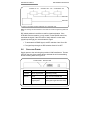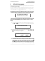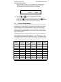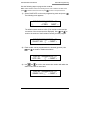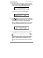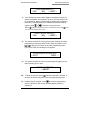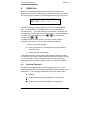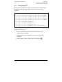
1
KTD-460/463
Alarm Input Module and
Alarm Chassis
© 2003 Kalatel, a GE Interlogix company
All Rights Reserved.
Any GE Interlogix, Kalatel division,
software supplied with GE Interlogix,
Kalatel division, products is proprietary and
furnished under license and can be used
or copied only in accordance with the
terms of such license.
This document contains proprietary
information that is protected by copyright.
No part of this document may be
reproduced or transmitted in any form or
by any means without the prior written
permission of GE Interlogix, Kalatel
division.
The information contained in this
document is subject to change without
notice. GE Interlogix, Kalatel division, in
keeping pace with technological advances,
is a company of product innovation.
Therefore, it is difficult to ensure that all
information provided is entirely accurate
and up-to-date. GE Interlogix, Kalatel
division, accepts no responsibility for
inaccuracies or omissions and specifically
disclaims any liabilities, losses, or risks,
personal or otherwise, incurred as a
consequence, directly or indirectly, of the
use or application of any of the contents of
this document.
For the latest product specifications, visit
GE Interlogix, Kalatel division, online at
www.GE-Interlogix.com or contact your
Kalatel sales representative.
For technical support before and after installation, call 800-469-1676.
Technical support is available 24 hours a day, 7 days a week.
Call:
Fax:
Web:
Tech Support 800-469-1676 (6 A.M. – 5 P.M. PST Monday through Friday)
Tech Support 541-740-3589 (all other times)
Main
800-343-3358 or 541-754-9133
Tech Support 541-752-9096 (available 24 hours a day)
Main
541-754-7162
www.GE-Interlogix.com
1041310B / March 2003
KTD-460/463 User Manual
Table of Contents
TABLE OF CONTENTS
BEFORE YOU BEGIN ................................................................4
1
KTD-463 INTRODUCTION ..................................................5
1.1 PLACEMENT IN A SYSTEM ...........................................5
1.2 INSTALLATION............................................................6
1.3 CONNECTING THE CABLES .........................................6
1.4 CONNECTING THE PRINTER (OPTIONAL).......................8
2
KTD-460 INTRODUCTION ..................................................9
2.1 PLACEMENT IN A SYSTEM ...........................................9
2.2 INSTALLATION..........................................................10
2.3 MOUNTING THE UNIT ................................................10
2.4 CONNECTING THE CABLES ........................................10
2.5 SETTING THE DIP SWITCH........................................13
2.6 SUPPLYING POWER .................................................14
3
KTD-463 PROGRAMMING ................................................15
3.1 CONTACT PROGRAMMING ........................................16
3.2 PRINTER SETUP ......................................................20
3.3 SETUP MENUS ........................................................21
4
OPERATION ....................................................................24
4.1 SHUNTED CONTACTS ...............................................24
4.2 PRINTED REPORTS ..................................................25
1041310B / March 2003
3
Before You Begin
KTD-460/463 User Manual
BEFORE YOU BEGIN
Read these instructions before installing or operating this product.
Note: This installation should be made by a qualified service person and should conform to
local codes.
This manual provides installation and operation information. To use this
document, you must have the following minimum qualifications:
• A basic knowledge of CCTV systems and components
• A basic knowledge of electrical wiring and low-voltage electrical
hookups
Use this product only for the purpose for which it was designed.
Customer Support
For assistance in installing, operating, maintaining, and troubleshooting
this product, refer to this document and any other documentation
provided. If you still have questions, contact Kalatel Technical Support:
GE Interlogix, Kalatel division
Call: 800-469-1676
Fax: 541-752-9096
Note: You should be at the equipment, ready with details before calling Technical Support.
Conventions Used in this Manual
Boldface or button icons highlight command entries. The following
WARNING, CAUTION, and Note statements identify potential hazards:
* WARNING:
Improper use of this equipment can cause severe bodily injury or
equipment damage.
** CAUTION:
Improper use of this equipment can cause equipment damage.
Note: Notes contain important information about a product or procedure.
* This symbol indicates electrical warnings and cautions.
** This symbol indicates general warnings and cautions.
4
1041310B / March 2003
KTD-460/463 User Manual
1
KTD-463 Introduction
KTD-463 INTRODUCTION
®
The KTD-463 desktop alarm is used in Digiplex systems for automatic
camera call-up, site annunciation, and preset camera positioning during
an alarm event. The KTD-463 operates in combination with KTD-460
alarm input modules, each of which provides 16 alarm inputs. Up to 16
KTD-460s can be connected to the KTD-463 via RS485 twisted-pair
cable, for a total of 256 alarm contact inputs.
1.1
PLACEMENT IN A SYSTEM
The KTD-463 must be placed ahead of all other Digiplex components on
the RS422 line. With two KTD-463s, one must be configured as the
master and one as the slave. The slave must be placed ahead of the
master on the RS422 line. A KTD-83 can be used to provide a return
RS422 cable to the KTD-463. See Figure 1 and Figure 2.
Keypad
Video switcher
KTD-83
Additional PTZ
receivers
CyberDome
KTD-460s (8)
KTD-460s (8)
KTD-463
Figure 1. System placement of one KTD-463
1041310B / March 2003
5
KTD-463 Introduction
KTD-460/463 User Manual
Video
switcher
Keypad
KTD-83
PTZ receivers
KTD-463
master
KTD-460 inputs
(0 – 255)
KTD-463
slave
KTD-460 inputs
(256 – 511)
Figure 2. System placement of two KTD-463s
1.2
INSTALLATION
CAUTION:
Complete all instruction steps before supplying power to the unit.
1.3
CONNECTING THE CABLES
See Figures 3 through 5.
1)
Locate the removable terminal strips on the rear of the KTD-463.
2)
Make cable connections as shown in Figures 3 through 5.
• Observe polarity when connecting the Digiplex RS422 control
cable.
• Observe polarity when connecting the RS485 alarm input cables.
3)
6
Supply power to the unit using the provided 9 VAC transformer.
1041310B / March 2003
KTD-460/463 User Manual
KTD-463 Introduction
Power
Fuse
RJ45
(RS232
6-pin
terminal
strip
16-pin terminal strips
Figure 3. KTD-463 back panel connections
Out
In
Relay
Relay output
RS422 control
signal input
RS422 control
signal output
Figure 4. KTD-463 six-pin terminal strip connections
1041310B / March 2003
7
KTD-463 Introduction
KTD-460/463 User Manual
RS485 signal input (up to 16 KTD-480s can be installed on one line or in any
combination on separate lines)
Figure 5. KTD-463 16-pin terminal strip connections
1.4
CONNECTING THE PRINTER (OPTIONAL)
A serial printer can be connected to the system using the RJ45 eight-pin
modular jack located on the rear of the unit. See Figure 6.
Figure 6. KTD-463 printer cable pinout connections (RS232)
Refer to section 3, KTD-463 Programming, for initial setup and
programming of the KTD-463.
Note: The KTD-463 cannot be programmed for proper operation until the KTD-460 alarm
input modules have been installed.
8
1041310B / March 2003
KTD-460/463 User Manual
2
KTD-460 Introduction
KTD-460 INTRODUCTION
The KTD-460 alarm input module provides 16 alarm inputs: supervised,
non-supervised, dry contacts, or voltage sources.
Each supervised contact input communicates a status level of normal
(contact not activated), alarm (contact activated), or trouble (short or
break on the alarm input line) to the KTD-463.
The KTD-460 also has an output relay that is energized when any alarm
contact is closed.
2.1
PLACEMENT IN A SYSTEM
Up to 16 KTD-460 alarm input modules can be connected to the
KTD-463 via RS485 twisted-pair cable. All 16 modules can be “daisy
chained” on one line or can be connected in any combination on multiple
lines (up to 16 individual KTD-460s on 16 separate lines). See Figure 7.
Figure 7. Examples of KTD-460 to KTD-463 connections
Note: If more than one KTD-460 is connected to the KTD-463 on the same alarm input
port, it must be connected in a “daisy chain” (loop through) configuration on a single line. It
cannot be connected in a parallel configuration.
1041310B / March 2003
9
KTD-460 Introduction
2.2
KTD-460/463 User Manual
INSTALLATION
CAUTION:
Complete all instruction steps before supplying power to the unit.
2.3
MOUNTING THE UNIT
Mount the unit on a wall or flat surface using the slots provided.
2.4
CONNECTING THE CABLES
Locate the removable terminal strips. See Figure 8 and Figure 9.
16-pin
terminal strips
6-pin
terminal strip
Cover screw (2)
Mounting flange
(2)
Power jack
10-position
DIP switch
LEDs
Figure 8. Top view of KTD-460
10
1041310B / March 2003
KTD-460/463 User Manual
KTD-460 Introduction
Out
In
Relay
Relay output
RS485
signal input
RS485
signal output
Figure 9. KTD-460 six-pin terminal strip connections
• Observe polarity when connecting the RS485 alarm cables.
• If voltage sources are used, observe polarity when connecting
alarm contacts.
Inputs
Inputs
Figure 10. KTD-460 16-pin terminal strip connections
Figure 11 shows the two types of supervised alarm contact
configurations for the KTD-460: normally open and normally closed.
1041310B / March 2003
11
KTD-460 Introduction
Normally open configuration
KTD-460/463 User Manual
Normally closed configuration
Alarm: contact closed
Alarm: contact open
Trouble: break before resistor
Trouble: short before resistor
Figure 11. Supervised contact configurations (resistor = 8.2K Ω)
Note: A supervised contact indicates that the alarm contact line contains a resistor.
Unsupervised contacts (no resistors) can be installed on the KTD-460, in which case the
REPORT TROUBLE feature must be disabled (see section 3.3, Setup Menus).
12
1041310B / March 2003
KTD-460/463 User Manual
2.5
KTD-460 Introduction
SETTING THE DIP SWITCH
Locate the 10-position DIP switch on the KTD-460 (Figure 8) and set as
follows:
DIP switch positions
1 through 4 are used
to set the module
address. Each
module will have an
address range from
0 to 15. See Table 1.
Table 1. DIP switch settings for module addresses
DIP switch
setting
Module
Address
DIP switch
setting
Module
Address
0
8
Note: DIP switch positions
5 through 8 are not
programmed for use.
1
9
Note: The module
addresses do not need to
be set in sequential order,
nor in the order in which
they are installed. (For
example, modules 0, 8,
and 5 could be daisy
chained on the same
RS485 alarm input cable.)
See Figure 12.
2
10
3
11
4
12
5
13
6
14
7
15
1041310B / March 2003
13
KTD-460 Introduction
KTD-460/463 User Manual
Contacts 0 – 15
Contacts 128 – 143
Contacts 80 – 95
KTD-460
KTD-463
Figure 12. Example of module addresses not in sequential order
Note: Do not assign the same address to more than one module. Programming failure will
occur.
DIP switch positions 9 and10 are used for signal termination. If the
KTD-460 is the last module, or only module, on the RS485 control line,
terminate the signal. If the KTD-460 is “daisy chained” to other units
(signal loop-through), do not terminate the signal.
• To terminate the RS485 signal, set DIP switches 9 and 10 to ON.
• For signal loop through, set DIP switches 9 and 10 to OFF.
2.6
SUPPLYING POWER
Supply power to the unit using the provided 9 VAC transformer. The two
LEDs on the side of the module blink to indicate the unit is transmitting
and/or receiving data. See Figure 13.
Transmit LED
LED
Receive LED
Blink Pattern
Status
Transmit
Short, regular pulse
Operating normally
Receive
None
Only one unit on RS485 line
Short or long,
regular pulse
More than one unit on RS485 line
(pulse gets longer with more units)
Figure 13. KTD-460 power LEDs
14
1041310B / March 2003
KTD-460/463 User Manual
3
KTD-463 Programming
KTD-463 PROGRAMMING
Note: The KTD-463 cannot be programmed for proper operation until the KTD-460 alarm
input modules have been installed.
For new installations, follow the programming instructions in the order in
which they are given. To update programming, enter the programming
mode and advance to the appropriate screen.
All programming menus will be displayed on the KTD-463’s LCD screen.
The first time power is supplied to the unit the following menu appears:
NO MODULES ENABLED!
ENTER PROGRAM MODE
This menu will not be displayed again after programming data is entered,
unless the CLEAR MEMORY option is selected in section 3.3, Setup
Menus.
1)
To enter the programming mode, simultaneously press and hold
and
keys for 3 seconds. The following prompt appears:
the
ENTER ACCESS CODE
2)
Enter the security code by sequentially pressing
. The following screen appears:
,
,
,
,
CONFIG:MASTER (NO SLAVE)
↑↓
3)
←EXIT
NEXT→
A second KTD-463 can be configured as a slave chassis, providing
an additional 256 alarm contact inputs. The slave chassis must be
located ahead of the master on the RS422 control line. Use the
keys to scroll through the choices: MASTER (NO SLAVE),
and
MASTER (w/SLAVE), and SLAVE. For systems with one KTD-463
(less than 256 alarm contact inputs), select MASTER (NO SLAVE).
1041310B / March 2003
15
KTD-463 Programming
KTD-460/463 User Manual
Note: All contacts on the slave unit are programmed from the master chassis.
However, finding and enabling KTD-460 modules connected to the slave is
performed from the slave chassis (see section 3.3, Setup Menus).
ENTER CHOICE: CONTACTS
↑↓
4)
←EXIT
NEXT→
Use the
and
keys to scroll through the choices:
CONTACTS, SETUP, and PRINTERS. When a choice has been
made, press
to advance to the next menu or press
to return
to the start-up menu or the normal operating display.
3.1
CONTACT PROGRAMMING
The alarm contacts on the KTD-460s can be programmed for automatic
camera call-up, site annunciation, and preset camera positioning. Each
alarm contact input can be programmed to initiate any or all of these
functions. Before programming the contacts, however, it is important to
understand the relationship between the contact number and the alarm
input module number.
The KTD-463 assigns a numerical value to each contact connected to a
KTD-460 based on the module’s address (0 – 15), and the pin (1 – 16)
each contact is connected to. For example, contact 2 on module 2 would
be assigned a value of 33. See Table 2 to determine the contact number.
Table 2. Contact numerical values based on module number and pin
Module #
Pin
Connection
Contact
Range
Module #
Pin
Connection
Contact
Range
0
1 – 16
0 – 15
8
1 – 16
124 – 143
1
1 – 16
16 – 31
9
1 – 16
144 – 159
2
1 – 16
32 – 47
10
1 – 16
160 – 175
3
1 – 16
48 – 63
11
1 – 16
176 – 191
4
1 – 16
64 – 79
12
1 – 16
192 – 207
5
1 – 16
80 – 95
13
1 – 16
208 – 223
6
1 – 16
96 – 111
14
1 – 16
224 – 239
7
1 – 16
112 – 127
15
1 – 16
240 – 255
16
1041310B / March 2003
KTD-460/463 User Manual
KTD-463 Programming
Use the following steps to program the contacts.
Note: Unless otherwise noted, in the following menus, when a selection has been made
press
1)
to advance to the next menu or press
to return to the previous menu.
Select CONTACTS on the main programming menu and press
The following menu appears:
.
CONTACT:000@MOD:00 - 01
↑↓
←PREV
NEXT→
The default contact number is 000. (The module number and pin
and
to
connection of the contact are also displayed). Use
scroll to the number of the first alarm contact you wish program.
CONTACT:000@MOD:00 - 01
SHUNT? NO ↑↓ ←NEXT→
2)
Each contact can be programmed to be shunted (ignored). Use
and
to enable or disable this feature.
CONTACT:000@MOD:00 - 01
SITE: 000
↑↓ ←NEXT→
3)
and
to scroll to the camera site number with which the
Use
alarm contact will be associated.
CONTACT:000@MOD:00 - 01
SENSE: N.O. ↑↓
←NEXT→
1041310B / March 2003
17
KTD-463 Programming
4)
KTD-460/463 User Manual
The alarm contacts will be configured as normally open (NO), or
normally closed (NC). This affects how the KTD-463 reports a
trouble state on an alarm input line (see Step 6 in section 3.3,
and
to select whether the KTD-463
Setup Menus). Use
senses the alarm contact as normally open or normally closed.
CONTACT:000@MOD:00 - 01
VID ALRM: YES ↑↓ ←NEXT→
5)
If a monitor is in the alarm mode and the "Video Alarm" feature is
being used, the camera site associated with the alarm contact will
appear on the monitor screen when an alarm event occurs (unless
and
to enable or
the monitor is disarmed for that site). Use
disable the video alarm feature.
CONTACT:000@MOD:00 - 01
HOLD DLY: 00 ↑↓ ←NEXT→
6)
Each alarm contact can be programmed with a hold delay that will
keep the alarmed site on the monitor screen for a specified period
of time after the alarm condition has ended.
To use this function, enter the desired hold delay time (00 – 14
and
keys. To have the alarmed site
seconds) using the
display indefinitely, scroll until hold delay time reads INF. In this
case a manual command is required from the keypad (e.g.,
CLEAR ALARM) to clear the site from the screen after an alarm
event.
CONTACT:000@MOD:00 - 01
ANNUNC?: NO ↑↓ ←NEXT→
18
1041310B / March 2003
KTD-460/463 User Manual
7)
KTD-463 Programming
If this setting is used, an alarmed site will be annunciated at the
keypad as a site call-in when an alarm occurs. For this function to
be used, the controller keypad must be programmed for
annunciation, as explained in the keypad installation and operation
and
to enable or disable annunciation. A
manual. Use
looping RS422 control cable configuration is required (see
Figure 1).
Note: External devices are required for site annunciation functions. Contact the
factory for details.
CONTACT:000@MOD:00 - 01
PRESET: NONE ↑↓ ←NEXT→
8)
With this setting, if the controller keypad and PTZ receivers have
been programmed for preset positioning, the camera will move to
an assigned position when an alarm occurs. In addition, if preset
tours have been assigned, this setting can be used to activate the
tours. Example: Alarm contact 2 is assigned to tour 2 on camera 1.
When alarm contact 2 is activated, camera 1 will begin its
preprogrammed tour 2.
If presets are being used, determine the number of the preset
and
position programmed into the site's PTZ receiver. Use
to enter the same preset number. If tours are being used
and
to assign a contact to a tour
(maximum of four), use
number.
CONTACT:000@MOD:00 - 01
MACRO NUM: NONE ↑↓ ←NEXT→
9)
10)
This setting is used to assign a programmed macro to an alarm
contact. Macro programming is done during setup. Currently,
macros are reserved for custom Digiplex commands provided by
the factory.
Exit to the main programming menu, and repeat steps 1 through 9
for the next alarm contact.
1041310B / March 2003
19
KTD-463 Programming
3.2
KTD-460/463 User Manual
PRINTER SETUP
The KTD-463 features an RS232 serial port (eight-pin, RJ45 jack), which
can connect to a printer or another serial device. This enables the user to
print setup reports and hard copies of contact activity (see Figure 14).
Use the following steps to enable the printer.
Note: Unless otherwise noted, in the following menus, when a selection has been made
press
1)
to advance to the next menu, or press
to return to the previous menu.
Select PRINTER on the main programming menu and press
The following menu appears:
.
ENABLE PRINTER: NO
YES ↑
NO ↓
←NEXT→
2)
to enable the printer. Press
to disable the printer (if
Press
already enabled). Pressing
or
will return to the main
programming menu. If the printer is enabled, the following menu
appears:
HANDSHAKE PROT: NONE
↑↓
3)
←PREV
NEXT→
Handshake protocol determines how data will be buffered by the
printer (or serial device). Use
and
to select NONE or
CTS/RTS. Check with the documentation provided with the printer
(or serial device) for protocol requirements.
PRINTER BAUD RATE: 9600
↑↓
20
←PREV
NEXT→
1041310B / March 2003
KTD-460/463 User Manual
KTD-463 Programming
4)
This menu is used to set the baud rate of data transmitted on the
RS232 serial line. The default is 9600 (KTD-463 maximum). If the
serial device requires a slower rate, use
and
to select
1200, 2400, 4800, or 9600.
5)
Printer setup is complete. Press
programming menu.
3.3
to return to the main
SETUP MENUS
When the alarm contacts have been programmed, the alarm chassis can
be programmed for operation. Use the following steps.
Note: Unless otherwise noted, in the following menus, once a selection has been made
press
1)
to advance to the next menu, or press
to return to the previous menu.
Select SETUP on the main programming menu and press
following menu appears:
. The
CLEAR MEMORY?
YES↑
2)
NO↓
←NEXT→
The CLEAR MEMORY option will erase all data in the alarm
chassis’ nonvolatile memory and reload factory default values. To
. The following menu appears:
clear the chassis’ memory, press
ARE YOU SURE?
←NO
3)
YES→
to reload the chassis’
This menu offers a safety check. Press
memory with factory default values. The screen will return to the
master/slave menu. Press
for no change.
FIND MODULES?
YES↑
1041310B / March 2003
NO↓
←NEXT→
21
KTD-463 Programming
4)
KTD-460/463 User Manual
When the KTD-460s have been installed, the KTD-463 must find
and enable each module. Press
to initiate an automatic search
for each module. The following menu appears momentarily:
ALL ACTIVE MODULES
WILL BE ENABLED
When a module is found, it is automatically enabled:
MODULE: 00 ENABLED
PORT:04 STOP↓ ←NEXT→
5)
to stop the scrolling and hold on the module displayed.
Press
advances to the report trouble menu. When the status
Pressing
of all modules has been reported, the display automatically
advances to the next menu.
Note: On new installations, or if new alarm input modules are added to the system,
this procedure must be followed for the KTD-463. If a KTD-463 slave chassis is
added to the system, this procedure must be performed by the slave unit.
REPORT TROUBLE? YES
YES↑
NO↓ ←NEXT→
6)
The KTD-460 modules feature supervised contacts, so the status
level (normal, alarm, trouble) of each contact is continually
monitored. The menu above enables a global alert if any alarm
and
contact is in a trouble state (short in the line, etc.). Use the
keys to enable or disable this feature.
If unsupervised alarm contacts were installed on the KTD-460 (no
resistors on the alarm contact line), select NO for this feature
(applies for all contacts).
Note: Trouble states are reported to external devices (keypad controller, Paragon®
GUI).
22
1041310B / March 2003
KTD-460/463 User Manual
KTD-463 Programming
PROGRAM MACRO?
YES↑
7)
NO↓
←NEXT→
The KTD-463 can send custom Digiplex commands (macros) for
special operational circumstances. Up to 64, five-step macros can
be programmed. Macro programming procedures are provided by
the factory. Unless directed to do otherwise by Kalatel technical
or
to advance to the next menu.
support, press
Note: If
(YES) is inadvertently pressed, on subsequent menus press
you return to the program macro menu.
until
PRINT SETUP REPORT?
YES↑
NO↓ ←NEXT→
8)
This feature enables the user to print a report detailing all contact
programming information and KTD-463 setup information. Press
,
to skip this and return to the main programming menu.
If you select YES, the following menu appears:
ALIGN PAPER IN PRINTER?
←EXIT
9)
NEXT→
This feature enables the user to manually align the paper (on dot
matrix printers) prior to print.
PRINTING REPORT
←ABORT
10)
To abort the print job, press
. When the print job is finished, or
aborted, the screen will return to the main programming menu.
11)
at the main programming
Programming is complete. Press
menu to advance to the normal operating display (section 4,
Operation).
1041310B / March 2003
23
KTD-463 Programming
4
Operation
OPERATION
When the KTD-460 alarm input modules have been installed and
programmed, and the KTD-463 setup procedures have been performed,
the unit will begin operations. The following appears on the LCD screen:
MODULE ADDR: 00 PORT: 01
000 – 015: – –A– – – T– – – – – – –
The normal operating display shows the alarm input module address
(00 – 15), which alarm port (RS485 alarm input line) the module is
connected to (01 – 16), and the status of each contact. The display will
automatically scroll through each module (every 2 to 3 seconds) showing
or
. To scroll another
its status. To pause the display, press
module, press
or
.
The dashed lines (or arrows) next to the alarm contact numbers
represent each contact connection and indicate the following:
– (dash) = normal (okay) state
A = alarm (contact open, if normally closed; contact closed, if
normally open)
T = trouble (contact not reporting)
In the above example, we see that contact number 2 (the third contact)
on module 0 is in an alarm state. Contact number 6 (the seventh contact)
is in a trouble state. This indicates either the contact has lost power
(through tampering or power outage) or that it is not properly installed.
4.1
SHUNTED CONTACTS
If a contact was shunted during contact programming, the A, T and –
(dash) displayed on the Normal Operating Display will be replaced with a
lowercase “s.” The s changes depending on the state of the contact:
s = shunted.
s = shunted contact closed (regardless of contact sense).
s = shunted contact open (regardless of contact sense).
24
1041310B / March 2003
KTD-460/463 User Manual
4.2
Operation
PRINTED REPORTS
If the printer is enabled (see section 3.2, Printer Setup), a hard copy of
KTD-460 module and alarm contact activity will be printed. See
Figure 14.
Date
Time
Site
Contact #
Status Input
Activity
09-24-99 11:05:32 SITE 128
CONTACT 128 CLSD
MOD-08-01 ALARM ON
09-24-99 11:05:37 SITE 128
CONTACT 128 SUPR
MOD-08-01 ALARM OFF
09-24-99 11:05:43 SITE 128
CONTACT 128 OPEN
MOD-08-01 TROUBLE ON
09-24-99 11:05:57 SITE 128
CONTACT 128 SUPR
MOD-08-01 TROUBLE OFF
09-24-99 11:06:05 MODULE 08 TROUBLE ON
09-24-99 11:06:12 MODULE 08 TROUBLE OFF
09-24-99 11:06:23 SITE 129
INF ALARM CLEAR
09-24-99 11:06:28 SITE 131
CONTACT 131 CLSD
MOD-08-04 ALARM ON
Figure 14. Example of printed activity report
Notes on printed reports:
• Module trouble indicates the associated KTD-460 became
disconnected or disabled.
• Infinite alarms can be cleared only by an external controller
(keypad).
• Under “status,” CLSD = closed; SUPR = supervised.
1041310B / March 2003
25