1
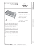
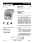
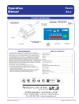
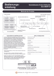
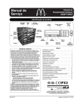
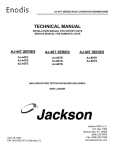
Operating
Instructions
Vertical Contact Toaster
296 & 297 Series
Limited Warranty
This product is warranted to be free from defects in
material and/or workmanship for a period of 1 year from
date of original installation, not to exceed 18 months
from the date of manufacture.
Any component which proves to be faulty in material
and/or workmanship will be replaced or repaired (at the
option of Prince Castle, Inc.) without cost to the
customer for parts and labor. This warranty covers on
location service (i.e. trip charges and/or mileage). Travel
mileage is limited to 100 miles (200 Kilometers) round
trip (one trip warranty) from an authorized service
agency or its sub-service agency.
This warranty is subject to the following exceptions/
conditions:
• Use of any non-genuine Prince Castle parts voids
this warranty.
• All labor to be performed during regular work hours.
Overtime premium (the incremental amount) will be
charged to the customer.
• Damage caused by carelessness, neglect and/or
abuse (e.g., dropping, tampering or altering parts,
equipment damaged in shipment, by fire, flood or an
act of God) is not covered under this warranty.
• All problems due to operation at voltages other than
that specified on equipment nameplates are not
covered by this warranty. Conversion to correct
voltage is the customer’s responsibility.
• This equipment must be serviced by Prince Castle
Authorized Service Agency or a Prince Castle
Service Technician during the warranty period.
• Normal adjustments as outlined in this manual are
not covered under warranty.
• Motors that fail due to the lack of monthly lubrication
will not be covered under warranty.
Electrical Specifications
Volts
230
110/120
220
Hz
60
60
50/60
Watts
1700
1700
1700
Amps
7.5
15.5
7.5
Table of Contents
Installation . . . . . . . . . . . . . . . . . . . . . . . . . . . . . . .
2
Operation . . . . . . . . . . . . . . . . . . . . . . . . . . . . . . .
2
Adjustments . . . . . . . . . . . . . . . . . . . . . . . . . . . . .
3
Cleaning . . . . . . . . . . . . . . . . . . . . . . . . . . . . . . . .
4
Troubleshooting . . . . . . . . . . . . . . . . . . . . . . . . . . .
5
Parts List . . . . . . . . . . . . . . . . . . . . . . . . . . . . . . 5 – 8
Wiring Diagram . . . . . . . . . . . . . . . . . . . . . . . . . . .
197-538revC-EN
9
355 East Kehoe Blvd. • Carol Stream, IL 60188 USA
Telephone: 630-462-8800 • Fax : 630-462-1460
Toll Free: 1-800-PCASTLE
www.princecastle.com
Printed in USA 6/06 © 2006
6.
Installation
1.
Slide the release sheet holding bracket onto the top of
the platen housing.
After you have removed the toaster from the carton,
inspect the unit for signs of damage. If there is damage
to the unit:
• Notify carrier within 24 hours after delivery.
Holding Bracket
• Save carton and packing material for inspection
purposes.
• Contact your Prince Castle dealer or the
Prince Castle Customer Sales Department at
1-630-462-8800 if purchased directly.
2.
Figure 3
7.
Attach conveyor to the toaster by sliding the four pins
(conveyor slides) on the conveyor housing into the four
conveyor guides. Lower the conveyor housing until it is
securely in place.
8.
Hook the back end of the crumb tray onto the bar
located below the conveyor assembly.
Plug unit into a grounded receptacle.
Verify that all parts have been received.
• Slim-Line Bun Toaster and conveyor assembly.
• Release Sheet Kit — located in a 14" box.
• Crumb Tray — taped to the front of the conveyor.
3.
Place toaster on flat surface. Remove protective
covering.
9.
4.
Lift conveyor off conveyor guide rails and set aside.
Remove all packing materials (nylon tape, foam block,
plastic coating on sheet metal, and black rubber
packaging spacers) from conveyor and conveyor
guides.
Operation
1.
Conveyor Guides
Power Switch
Figure 1
5.
Turn the Power switch to the “On” position. The orange
indicator light will illuminate. Allow 30 minutes for platen
to reach operating temperature.
Figure 4
Place the Teflon sheet over the top of the platen
housing, making sure to have three inches of overhang.
2.
3-inch Overhang
Place a sample run of the product being toasted into
the top of the conveyor housing. The side to be toasted
should face the platen.
Release Sheet
Figure 2
Figure 5
Printed in USA 6/06 © 2006
2
3.
The toasted product will be dispensed automatically
from the bottom of the conveyor assembly.
4.
Verify that product meets acceptable standards. If not,
see adjustment section.
197-538revC-EN
Bun Compression:
Adjustments
The toaster platen can be adjusted to provide the necessary
compression needed on various products.
• Turn the two platen adjustment knobs clockwise to
compensate for use on thicker bread products. Turn
the two platen adjustment knobs counterclockwise
for thinner products. The numbers on the front of the
end and motor housing will indicate the settings, 1 for
thinnest product, 5 for thickest.
Conveyor and Motor Gears:
There will be a 1/64" clearance between the conveyor gear
and motor gear when properly aligned. Improper alignment
will cause the conveyor to periodically bind.
1/64" Clearance
Gears
Properly
Mesh
Thermostat Knob
Figure 6
Tools Needed:
3/32" Allen wrench
Wicking grade thread locking fluid
1.
2.
Platen Adjustment
Knobs
Working from the “back side” of the toaster, loosen the
2 setscrews at the bottom of the conveyor guide until
they are even with the conveyor stop. Note: the
conveyor assembly may need to be removed for easier
access.
Figure 8
Use the Allen Wrench to tighten the left setscrew (end
housing side) until the setscrew just touches the
conveyor slide.
THICKER
5
Top of the #10-32 Setscrew
Both Sides
4
3/32 Hex
Head Key
3
2
1
THINNER
Figure 9
Figure 7
Platen Temperature:
3.
Tighten the right setscrew (motor housing side) until
the bottom of the conveyor housing is parallel to the top
of the base.
4.
Carefully tighten each setscrew another 1/2 turn.
5.
Remove the conveyor assembly.
The temperature of the platen can be adjusted to
compensate for darker or lighter toasting requirements.
• Turn the thermostat adjustment knob clockwise for
darker toasting. Turn the thermostat adjustment knob
counterclockwise for lighter toasting.
6.
Apply a drop of wicking grade thread locking fluid to
each setscrew.
IMPORTANT: Allow 15 minutes for toaster to stabilize after
adjusting the thermostat.
7.
Replace conveyor assembly.
197-538revC-EN
3
Printed in USA 6/06 © 2006
Cleaning
Preventive Maintenance (Motor)
CAUTION: This is not jet-water approved, and
should not be cleaned with a water hose or jet
spray.
To extend the life of your replacement motor, have an
authorized factory service technician or store manager wick
the shaft of the motor with 2-3 drops of oil every 3,000 hours
of run time.
CAUTION: Do not immerse in water.
1.
IMPORTANT: Unplug toaster before performing any
preventive maintenance.
Turn off the Power switch and unplug the toaster.
2.
Allow platen to cool for 60 minutes before cleaning.
3.
Remove the conveyor assembly.
4.
Wipe the conveyor with a damp cloth. For the chain use
a soft bristle brush.
5.
Remove the release sheet and lay it on a flat surface.
Thoroughly clean both sides with a damp cloth making
sure all carbon buildup is removed. Allow to air dry.
Shaft
IMPORTANT: Rotate two sheets daily for longer life. Sheets
last 4 – 6 months based on care and volume of product
toasted.
6.
Use a damp cloth to remove any carbon buildup on the
platen surface.
IMPORTANT: Do not use sharp objects, Scotch Brite pads,
scouring pads, or abrasive cleaners on the platen or Teflon
release sheets as it will cause irreparable damage.
Figure 10
Printed in USA 6/06 © 2006
4
197-538revC-EN
Troubleshooting
PROBLEM
Unit will not heat up.
PROBABLE CAUSE
No power to unit.
Power rocker switch light off.
Inoperable power cord.
Loose connection on power switch.
Inoperable power switch.
Unit will not heat up.
Inoperable thermostat.
Power rocker switch light on.
Inoperable platen.
Unit heats up, but the conveyor Loose motor switch connection.
does not run.
Inoperable motor.
Stripped drive gear.
Loose chain sprockets.
Gears not meshing.
Inoperable motor switch.
Inoperable thermostat.
Unit under- and over-heats
(does not respond to thermostat
adjustments).
Buns under or over done.
Check platen adjustment. (See Bun
Compression on page 3.)
Check platen temperature. (See Platen
Temperature on page 3.)
Front View
SOLUTION
Ensure power cord is connected to proper
receptacle and the power inlet.
Replace power cord.
Tighten power switch connections.
Replace power switch.
Replace thermostat.
Replace platen.
Tighten motor switch connection.
Replace motor.
Replace drive gear.
Adjust and tighten sprockets.
Adjust conveyor setscrews (see Conveyor and
Motor Gears on page 3).
Replace switch.
Replace thermostat.
Adjust platen for proper compression.
Adjust thermostat for proper temperature.
Parts List
5
Item
1
3
2
Part
Number
1
2
3
4
5
*
*
78-184S
197-185S
70-012
197-232S
197-124
197-475
197-259
*
197-402
*
297-151
*
297-149
*
197-260
Description
Power Lighted Rocker Switch
Platen Adjustment Knob (Pkg of 2)
Thermostat Knob
Foot (Pkg of 4)
Conveyor Guide with Handle
Overlay (Motor Housing)
Release Sheet Conversion Kit,
197/297
Release Sheet (Pkg of 2)
Conversion Kit 296 Series
Release Sheet (Pkg of 4)
297-T12PHH only
Clamp Bar
297-T12PHH only
Release Sheets (Pkg of 2),
297 Series
* Not shown.
4
197-538revC-EN
5
Printed in USA 6/06 © 2006
Conveyor Assembly
10
11
4
5
4
2
2
8
3
3
1
1
4
4
9
7
6
7
Parts List
Item
Part
Number
1
197-463S
2
197-459S
3
4
5
81-015
197-467
197-280
Printed in USA 6/06 © 2006
Description
Item
Left and Right Side Shaft Carrier
Assy
Left and Right Side Shaft Carrier
Adjustment Assy
Compression Spring
Conveyor Slide
Shaft Assy.
6
7
8
9
10
11
6
Part
Number
197-465
197-302
89-684
89-590
197-7S
197-466S
Description
Driven Shaft
Sprocket Kit (Pkg of 2)
Complete Chain Assy
Single Conveyor Chain Link
Black Handle with Screw
Complete Conveyor Assy (Passive)
197-538revC-EN
Rear View
12
13
2
3
11
14
10
15
9
8
16
4 Places
1
17
5
6
4
Parts List
Item
1
2
3
4
5
6
8
9
10
Part
Number
197-436S
197-476S
197-477S
197-437S
196-026S
197-114
197-473
76-225
197-131
197-33
197-497
73-007
197-16
76-165
76-640
197-96
Description
Item
Gear Kit (20/40 Second)
Gear Kit (12 Second)
Gear Kit (14 Second)
Gear Kit (30 Second)
Gear Kit (55 Second) (196-Jack)
Motor Cover
End Housing
Slotted Pan Head Screw
Guard
Crumb Tray
Crumb Tray (297-T12PHH only)
Hex Nut
Conveyor Stop
Setscrew
Screw
Left Side Bun Fence
11
12
13
14
15
16
17
Part
Number
73-008
73-030
79-016
76-033
76-640
197-13
197-97
197-431S
197-430S
196-023S
197-95
72-232S
72-233S
72-280S
*
Description
Self Locking Hex Nut
Hex Nut
Flat Washer
Slotted Flat Head Screw
Screw
Lead Pan Weldment
Right Bun Fence
Platen (220 Volt) (297)
Platen (110 Volt) (297)
Platen (110 Volt) (296)
Tray Support
Line Cord (CE)
Line Cord (GB)
Line Cord (120 Volt)
Instruction Card for 297-T12PHH
* Part not shown.
197-538revC-EN
7
Printed in USA 6/06 © 2006
Internal Components
Parts List
12
Item
11
1
2
10
3
4
5
6
7
1
9
8
6
13
9
1
2
10
8
11
12
13
4
Printed in USA 6/06 © 2006
76-300
87-028AS
87-029S
73-031
79-033
76-051
79-055
76-040
79-017
73-030
76-150
79-094
79-016
76-095
197-90
197-89
3
5
Part
Number
7
8
197-428
197-429
196-19
197-140
297-010S
Description
Slotted Pan Head Screw
Motor (208-240 Volt)
Motor (120 Volt)
Hex Nut
Washer
Slotted Binder Head Screw
Flat Washer
Slotted Binder Head Screw
Split Lock Washer
Hex Nut
Slotted Pan Head Screw
Flat Washer
Flat Washer
Slotted Binder Head Screw
LH Side Plate Weldment with
Adjustment Screw
RH Slide Plate Bracket with
Adjustment Screw
Baffle (Motor Housing)
Baffle (End Housing)
Housing
Thermostat with Knob
Thermostat with Knob and Thermo
Compound
197-538revC-EN
Wiring Diagram
Voltage Connection
High Voltage Connection (220-240 Volts)
197-538revC-EN
Low Voltage Connection (200-208 Volts)
355 East Kehoe Blvd. • Carol Stream, IL 60188 USA
Telephone: 630-462-8800 • Fax : 630-462-1460
Toll Free: 1-800-PCASTLE
www.princecastle.com
Printed in USA 6/06 © 2006