1
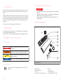
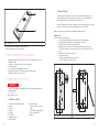
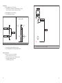
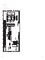
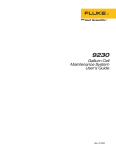
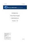
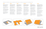
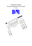
On-The-Wall Installation manual IMPORTANT: Read this manual carefully before using the fresh-r! Keep this manual for future use. Installation manual Contents 1. Intended use 4 2. Target group 4 3. Symbols used in this manual 3.1 Safety symbols 3.2 Other symbols 4 4 4 Foreword Installation manual for the contractor 4.General safety instructions 5 5. Main components 5 6. Tools needed for the installation 6 7. How to install the fresh-r? 6 Dear contractor, Thank you for purchasing the VAVENTIS fresh-r On-The-Wall. This manual is intended for professionals and contains all the necessary installation information. To install the fresh-r correctly and safely, it is essential that you read this information carefully and familiarize yourself with the fresh-r before you start. The fresh-r requires a 230 V mains electricity supply and must be connected by a qualified electrician. 8.Specifications 18 9.Who can I contact for questions, spareparts or more information? 18 Other information relating to the target group can be found in chapter 2. 10.Warranty 18 The information in this manual is important for the correct and safe installation of the fresh-r. With the table of contents you’ll be able to find the right information in the manual quickly. This is the installation manual. Besides this manual there is also an user manual available. 11. Frequently asked questions 19 12. Declaration of conformity 23 13.Appendix 24 13.1 Technical drawings fresh-r24 2 3 1. Intended use 4. General safety instructions DANGER The Vaventis fresh-r On-The-Wall is a decentral ventilation unit with heat recovery. The fresh-r takes heat from the stale air it expells and uses it to warm up the fresh air it brings in from outside. It improves air quality for a healthy indoor air quality and at the same time reduces your energy bill. No ducting is needed for this unit, which makes installation easier than a conventional HRV system. The fresh-r is equipped with CO², RH and temperature sensors and has an intelligent control system and other than conventional HRV’s the fresh-r also works efficient at sub zero temperatures. The Vaventis fresh-r On-The-Wall may only be installed on a wall. • Connecting the fresh-r to the mains electricity supply must be done by a qualified electrician. • Risk for electric shocks or electrocution. Turn off the mains electricity supply in the distribution box before connecting the fresh-r electrically. • The person responsible for installing the fresh-r should be familiar with the local building regulations. 5. Main components 2. Target group The manual describes how to install the fresh-r. The installation must be done by contractors who are familiar with local building regulations. Connecting the fresh-r to the mains electricity supply must be done by a qualified electrician. top side A B C 3. Symbols used in this manual D E 3.1 Safety symbols F DANGER Indicates an immediate risk of irreversible injury or death when not observed. WARNING Indicates a risk of severe personal injury and/or serious damage to the product if the procedures are not followed carefully. CAUTION Indicates that the product may be damaged if the procedures are not followed carefully. G H NOTICE Alerts the user to additional information and possible problems. fig. 1 Main components 3.2 Other symbols CE marking: This is the CE logo indicating that the fresh-r meets the legal requirements. 4 A. B. C. D. ON/OFF switch Power connection wire Unibody Front door (connected to the Unibody) E. F. G. H. Grilles Grilles cover Grilles assembly (2pcs) Duct pipes with EPP covers (2pcs) 5 2 Prepare the wall I You will need two round holes (Ø 160 mm) in the outer wall of the building, for the air pipes; the lowest hole needs to have a slope of 2 degrees. You also need four holes in order to attach the fresh-r on the wall with four screws 6 x 120. For efficient ventilation place the unit centrally in the room, ideally at least at 80 cm from the floor level, but not too high. You must be able to see the controls easily. J fig. 2 Main components I. Fresh air input socket, with fan (for upper duct pipe) J. Stale air output socket (for lower duct pipe) 6. Tools needed for the installation • Equipment to drill 2 round holes (Ø 160 mm) in the wall (typically water-cooled diamond core drill) • Pozidriv nr. 3 screw driver; for the 6 x 120 wood screws • 8 mm masonry drill • PVC cement (this is standard glue for hard PVC) • Spirit level (or another tool to check for a prefect vertical position) • Deburring or grinding tool, such as a file Mark the openings using the cardboard wall-cut/drilling template supplied. Draw the holes To draw the holes, do the following: 1. Place the template against the outer wall, make sure it’s vertical leveled. 2. Tape the template on the wall. Use removable tape in the corners. Make sure “UP” is visible and is pointing upwards. 3. Mark the centres of the big holes by tracing the four notches around the hole. Use a pencil and a ruler to make two crosses. The crosses mark the centres of the holes. 4. Mark the centre of the four corner holes. 5. Remove the template. Check the centre distance of the two big holes. The centre distance should be 897 mm. UP UP 7. How to install the fresh-r? DANGER • The person responsible for installing the fresh-r should be familiar with the local building regulations. 897 mm Please follow steps 1 to 10. 1 Check the contents 1 × Cardboard wall-cut/drilling template 1 × Unibody 1 × Front door 2 × PVC pipe 2 × EPP pipe 1 × User manual 1 × Installation manual 2 × Grilles assembly 6 3 × Bags with content: • Bag A, 4 screws 6 x 120 and 4 plugs • Bag B, Mounting kit for grilles • Bag C, Spare parts kit 1 × EPP glue fig. 3 Make sure the template is vertical leveled fig. 4 Draw two centres using the template 7 The big holes To drill the lower big hole, do the following: 1. Drill through the outer wall(s) at a downward angle of 2 degrees. This is to allow the condensate to drain towards outside. 243 mm To drill the upper big hole, do the following: 2. Drill straight through the wall(s). 105 mm Section cut AA 111 mm A Inside the Outside the house house 160 ± 2 mm 1055 mm 897± 2 mm 160 ± 2 mm 2 degrees A fig. 5 Make sure the wall is well prepared fig. 6 3. 4. Check the dimensions of the corner holes before drilling Remove dust and other materials from the holes. Get a duct pipe with EPP cover and try if it fits the holes. The four corner holes To drill the four corner holes, do the following: 1. Check the dimensions as shown in fig. 6. 2. Drill the four corner holes. Use a 8 mm masonry drill. 3. Place plugs into the four corner holes. You’ll find the plugs in bag A. 8 9 3 Cut the duct pipes 4Place the duct pipes in the Unibody NOTICE NOTICE Make sure if you cut the duct pipes, the part you want to keep has a lip. To cut the duct pipes, do the following: 1. Remove the EPP covers. 2. Cut the upper duct pipe (input fresh air) to the total width of the wall (D1) + 15 mm. Use the provided EPP glue for the lower duct pipe. The lower duct pipe is the condensate drain and needs to be water tight. Apply PVC glue to the last 3 cm of the duct and to the white ring. Apply the EPP glue to the EPP and the insulating foam around the pipe. Make an airtight connection: the air in the ducts can be very cold. No warm, moist indoor air may reach the cold ducts. 1. Tip: Use a wide tape or two paper sheets taped together to mark the duct pipes and get a perpendicular cut. 3. 4. Put PVC glue on the white ring which is located in the inside of the stale air output socket (see fig. 9). Do not put PVC glue on the freh air input tube. Cut the lower duct pipe (output stale air) to the total width of the wall(s) (D1) + 55 mm. Deburr the duct pipes. Use a deburring tool, such as a file. D1 + 15 mm D1 fig. 9 Put PVC glue in the stale air output socket on the white ring only 2. Place the duct pipes into the Unibody. Make sure the lips are pointed towards the bottom side of the Unibody. D1 + 55 mm Bottom side fig. 7 10 Determine D1 fig. 8 Make the duct pipes to the correct size fig. 10 Place the PVC duct pipes into the Unibody 11 3. Put EPP glue on the Unibody around the PVC duct pipes fig. 13 fig. 11 Put EPP glue around the edges of the covers Put EPP glue on the Unibody around the PVC duct pipes 4. Place the EPP covers on the duct pipes. Cut the Epp covers. They need to cover the whole duct pipe. The lips need to extend beyond the covers. fig. 14 Cut the EPP covers fig. 12 Place the EPP covers 5. Put EPP glue around the edges of EPP covers of the upper duct pipe and the lower duct pipe. NOTICE The connection of the lower duct pipe and the upper duct pipe to the Unibody needs to be airtight because air leaks will create unwanted condensation. 12 fig. 15 The lips need to extend beyond the covers 13 5 Mount the Unibody on the wall 1. 3. Remove the four corner bolts (don’t remove the middle bolts). The first person: Hold the Unibody as shown in fig. 18. Place the Unibody with the upper duct pipe and lower duct pipe in the wall. CAUTION Hold the Unibody till it’s mounted with the four 6 x 120 screws. fig. 16 Remove the four corner bolts The following steps need to be done by two persons. First read step 2, 3, 4 and 5 so you are well prepared. Then perform the actions. 2. Place the Unibody in vertical position and open the door as far as possible. fig. 18 Hold the Unibody as shown in this fig. 19 Place the Unibody on the wall figure 4. fig. 17 The second person: Mount the 6 x 120 screws in each corner of the Unibody (4 ×). Use a screw driver. Open the door as far as possible CAUTION Be carefull with the door. Giving too much pressure can damage the door or it’s hinges. 14 15 6Connect the fresh-r electrically and test its functionality 7 DANGER • Connecting the fresh-r to the mains electricity supply must be done by a qualified electrician. • Risk for electric shocks or electrocution. Turn off the mains electricity supply in the distribution box before connecting the fresh-r electrically. Place the grilles assembly (find the content in Bag B) Do the following: 1. Mount the grilles on the outer face of the outside-wall. 2. Place the covers. NOTICE The lip of the lower duct pipe should overlap with the edge of the grilles cover so condensate water is guided from the outer wall. Do the following: 1. Turn off the main electricity supply in the distribution box before attempting to wire in the fresh-r. 2. Make the electrical connection while the fresh-r is turned OFF. 3. Turn the main electricity supply ON again at the distribution box. 4. Turn the fresh-r ON. If you: • hear a sound AND; • see two working LED’s AND; • notice two working fans. The product works well. If not: Check the main electricity supply. If the product still does not work, turn the unit OFF and contact your supplier fig. 20 Place the grid assembly fig. 21 16 Lip should overlap with the edge of the grilles 17 8. Specifications Type On-The-Wall Serial nr. Can be found at the left side, above the middle Flow range 0-120 m3/hr Working range* -20oC to 50oC Max. power consumption 60 Watt Avg. power consumption 8 Watt Noise 30 dB(A) at 80 m3/hr according ISO3741 Efficiency (at 50m3/hr) 90% true eff. Control Certification automatic (on basis of CO² ppm) CE Weight Less than 20 kg Dimensions 1143 mm × 300 mm × 160 mm 9. Who can I contact for questions, spareparts or more information? Vaventis Achteromstraat 8a 1381 AV Weesp [email protected] T +31 294 261 171 www.vaventis.com 10.Warranty 2 years as stated in the General terms and conditions of Vaventis B.V. 11.Frequently asked questions Before installing What size building can one fresh-r ventilate? Up to 100 m2, but this depends on the size, lay-out, number of people and the regulations, ask your supplier for details. Where should I position the fresh-r in the building? Centrally and ideally at least 80cm from the floor level, but not too high because you need to be able to see the controls easily. Make sure air distributes evenly between different rooms. Ask your supplier for details Will the unit work in a bathroom? We do not recommend to use a frehs-r in the bathroom, we recommend to use an alternatieve solution, ask your supplier for details. Will the unit work in the toilet? Yes, contact your supplier for details. What should I do when the kitchen hood is on? Make sure there is enough airflow towards the kitchen hood, we recommend a kitchen hood with a maximum capacity of 300 m3/hr, contact your supplier for details. Will the air be distributed in the room? Yes, CO² travels easily but proper air circulation is needed between the rooms, contact your supplier for details. Where is the air extracted from the room? From the top of the door. Why should we not mount the unit close to the ground? Because it is more efficient to take warm air from the top of the room and it give better air circulation when bringing in fresh-r air in the middle of the room. While installing What distance is needed between the 2 duct holes? 897 +/- 2 mm from centre to centre. Why does the lower duct need to be positioned at a 2 degree angle? It needs to drain condensate to the outside. Why does the lip of the lower duct pipe need to have overlap with the grilles? In order to guide the water from the wall surface, so the condensate drops on the ground and not cause green streaks on the outer wall. Why does the lower duct pipe need a water tight connection with the Unibody? When heat is exchanged condensation can take place, this condensate is guided through the Unibody through the lower duct pipe to the outside. Can the fresh-r be installed horizontally? No, the condensate will not be guided correctly, contact your supplier for details. Can the fresh-r be mounted upside down? No, the condensate will not be guided correctly, contact your supplier for details. Where does the air enter the room? From the bottom of the door. 18 19 Does the upper duct pipe need to be positioned in a 2 degree angle? No, this can be level but it is no problem to mount it under a 2 degree angle, the upper duct does not drain any condensate, it only guides incoming air. How can I operate the unit? On the control panel, “A” for automatic. You can increase or decrease the fan speed manually using the fan buttons. Refer to the user manual. Increase or lower fans speed via the fan buttons; refer to user manual. Can we change the door to swing direction? Yes. First the electric cable needs to be removed. Then remove the 2 hinge bolds & nuts and mount them on the other side. Don’t forget to place back the electric cable. What does the smiley tell me? They indicate the air quality, refer to user manual. Should we first mount the upper and lower duct on the unit and then mount the Unibody on the wall? Yes, because the connection of the PVC duct pipes and the EPP covers needs to be checked visually before mounting the fresh-r in the wall. What should we do with bag C? This is a spare part kit, store it at the bottom of the unit. After installation Does the fresh-r start in the automatic program? Yes, it always runs in automatic mode, except when the fan speed is changed manually. After 100 minutes it will go back to automatic mode, refer to user manual. How will the fresh-r determine at what rate the it needs to operate? The higher the CO² level or the RH (relative humidity) levels the more it will ventilate, refer to user manual. I feel cold air coming out of the bottom, is that correct? Yes, moving air feels colder then stationary air, refer to user manual. 20 Does the unit measure RH or CO²? Yes, it measures both, please refer to user manual. What maintenance should be done? Rinse heat exchanger with cold water every 6 months, and clean upper and lower duct pipe every 2 years, refer to user manual. The unit makes noise, is that correct? If the orange or red face icon is lighted it is correct. The air quality is not good enough and it substantially increases the ventilation rate. If the green smiley is on and it makes more noise then 30 dB(A) it could be very humid inside, especially just after construction. If the green smiley is on and the building is not humid but the unit makes noise for more then 3 hours in a row, contact your supplier. Refer to user manual. 12.Declaration of conformity as required by EC Directive We The manufacturer: Vaventis b.v. Address: Achteromstraat 8a 1381 AV Weesp, The Netherlands declare under our sole responsibility that the following product E quipment: Air handling unit with heat recovery Brand name: Vaventis Model/type: Fresh-r is in conformity with the following Directives 2006/95/EC Low Voltage (LVD) the product bears the CE label How can we reduce the noise? Wait till the green light face lightens. If this takes too long, open a window. Refer to user manual. The fresh-r suddenly starts to make noise, but no air is coming into the room, what happens? If it is freezing outside, it is in defrost mode and it de-freezes the heat exchanger by blowing warm air out, so it can again work at optimum efficiency. If it is not freezing outside and the fresh-r suddenly starts to make noise, contact your supplier. Refer to user manual. 14 ……………………………………….. J. van Beuzekom (Managing Director) st Weesp, August 1 , 2015 21 13.Appendix 13.1 Technical drawings fresh-r 22 23 www.vaventis.com © 2015 by Vaventis B.V. All right reserved