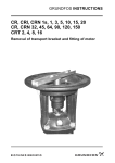
1
Operating Manual Euro-HYGIA® I Adapta Euro-HYGIA® I Adapta- SUPER Euro-HYGIA® I Adapta- V BA.022..Adapta.001.V1.GB 2 BA.022.Adapta.001.V1.GB Content FIGURES ........................................................................................................................................................... 5 TABLES ............................................................................................................................................................. 5 1.0 INTRODUCTION ............................................................................................................................................... 6 1.1 Target Group ..................................................................................................................................................... 6 1.2 Symbols and Formatting.................................................................................................................................... 6 1.3 References to the Document ............................................................................................................................. 6 1.4 ATEX – Notices to Explosion Protection............................................................................................................ 6 1.5 Rating Plate ....................................................................................................................................................... 7 2.0 SAFETY ............................................................................................................................................................ 7 2.1 Instructions for the Operator .............................................................................................................................. 7 2.1.1 General........................................................................................................................................................... 7 2.1.2 Safety Instructions in the Operating Manual .................................................................................................. 7 2.1.2.1 Identification of Instructions in the Operating Manual ................................................................................ 8 2.1.2.2 Qualifications and Training of Personnel ..................................................................................................... 8 2.1.2.3 Hazards Upon Failure to Follow the Safety Instructions ............................................................................ 9 2.1.2.4 Safety-Conscious Work ............................................................................................................................... 9 2.1.2.5 Safety Instructions for the Operator / User ............................................................................................... 9 2.1.2.6 Unauthorized Modifications and Production of Spare Parts.......................................................................10 2.1.2.7 Improper Operation ....................................................................................................................................10 2.1.2.8 Cleaning .....................................................................................................................................................10 2.1.2.9 Transport ....................................................................................................................................................11 2.2 Set-up / Installation...........................................................................................................................................11 2.2.1 Set-up and Alignment of the Pump Assembly .............................................................................................11 2.2.2 Installation in the Pipeline ..............................................................................................................................12 2.3 Electrical Connections ......................................................................................................................................13 2.4 Start-up / Shut down .........................................................................................................................................14 2.5 Repair Contract ................................................................................................................................................16 3.0 PRODUCT DESCRIPTION ..............................................................................................................................17 3.1 Proper Use .......................................................................................................................................................18 3.2 Design and Function of the Pump ....................................................................................................................19 3.3 Wet End Parts ..................................................................................................................................................20 3.4 Design Variations .............................................................................................................................................25 3.4.1 Euro-HYGIA Adapta...................................................................................................................................25 3.4.2 Euro-HYGIA Adapta- SUPER ....................................................................................................................25 3.4.3 Euro-HYGIA Adapta-V ...............................................................................................................................25 4.0 TECHNICAL DATA..........................................................................................................................................26 4.1 Maximum Working Temperatures.....................................................................................................................26 4.2 Maximum Operating Pressures ........................................................................................................................26 5.0 MAINTENANCE ...............................................................................................................................................27 5.1 Safety Instructions for Maintenance, Inspection, and Installation Work...........................................................27 5.2 Maintenance of the Pump.................................................................................................................................27 5.2.1 Maintenance of the Motor ..............................................................................................................................27 5.3 Maintenance of the Adapta® - Bearings............................................................................................................28 5.4 Roller Bearing Grease ......................................................................................................................................28 5.5 Troubleshooting................................................................................................................................................29 6.0 DISASSEMBLY................................................................................................................................................31 6.1 Disassembly of the Wet End Parts ...................................................................................................................31 6.2 Disassembly of the Pump with Single-Acting Spiral-Spring Mechanical Seal..................................................32 6.3 Disassembly of the Pump with Single-Acting Sterile Mechanical Seal ...........................................................32 6.4 Disassembly of the Pump with Double mechanical seal, back to back............................................................33 6.5 Disassembly of the Pump with Double Mechanical Seal, Tandem ..................................................................34 6.6 Disassembly of the Adapta® - Bearing Housing...............................................................................................35 7.0 ASSEMBLY......................................................................................................................................................36 7.1 Tightening Torques...........................................................................................................................................37 7.2 Greasing the Screws ........................................................................................................................................37 7.3 Assembling the Adapta® bearing housing.........................................................................................................38 7.4 Assembly of the Pump with Single- Acting Spiral-Spring Mechanical Seal ......................................................39 7.5 Assembly of the Pump with a Single- Acting Sterile Mechanical Seal ..............................................................39 7.6 Assembly of the Pump with Double Mechanical Seal, back to back................................................................40 7.7 Assembly of the Pump with Double Mechanical Seal, Tandem.......................................................................41 BA.022.Adapta.001.V1.GB 3 8.0 SPARE PARTS ................................................................................................................................................42 8.1 Euro-HYGIA® Adapta (SUPER) .....................................................................................................................42 8.2 Summary of Spare Parts for the Mounting Variations.......................................................................................45 Hilge Mechanical Seal Code...................................................................................................................................49 CERTIFICATE OF NON-OBJECTION...................................................................................................................50 SERVICE ADDRESSES FOR HILGE INTERNATIONAL ......................................................................................51 4 BA.022.Adapta.001.V1.GB Figures Figure 1: Example rating plate................................................................................................................................. 7 Figure 2. Transport ................................................................................................................................................ 11 Figure 3: Transport Euro-HYGIA®I Adapta®-V....................................................................................................... 11 Figure 4: Installation in pipelines. .......................................................................................................................... 12 Figure 5: Y-connected 3-phase system ................................................................................................................. 13 Figure 6: ∆-connection, ......................................................................................................................................... 13 Figure 7: Schematic of the sealing water system – pressurized. .......................................................................... 14 Figure 8: Schematic of the flushing water system - unpressurized...................................................................... 15 Figure 9: Valve assembly. .................................................................................................................................... 15 Figure 10: Wet End Parts (Variant KLM and HPM) ............................................................................................... 20 Figure 11: Single mechanical seal......................................................................................................................... 21 Figure 12:Single mechanical seal with seal cover ................................................................................................. 21 Figure 13: Single mechanical seal, Seat B3. ......................................................................................................... 22 Figure 14: Double mechanical seal, tandem ......................................................................................................... 23 Figure 15: Double mechanical seal, tandem. Seat B3.......................................................................................... 23 Figure 16: Double mechanical seal, back to back ................................................................................................. 24 Figure 17: Double mechanical seal, back to back, seat B2. .................................................................................. 24 Figure 18: Euro-HYGIA Adapta on cast iron foot ................................................................................................. 25 Figure 19: Euro-HYGIA Adapta on trolley .......................................................................................................... 25 Figure 20: Euro-HYGIA Adapta-SUPER on ball feed support............................................................................ 25 Figure 21: Euro-HYGIA Adapta® - V .................................................................................................................... 25 Figure 22: Assembly of the wet end parts ............................................................................................................. 31 Figure 23: Detail Klemmring .................................................................................................................................. 31 Figure 24: Spiral-spring mechanical seal............................................................................................................... 32 Figure 25: Sterile mechanical seal......................................................................................................................... 32 Figure 26: Double mechanical seal, back to back, 001seat................................................................................... 33 Figure 27: Double mechanical seal, back to back, seat B2. .................................................................................. 33 Figure 28: Double mechanical seal, tandem, seat B3 ........................................................................................... 34 Figure 29: Double mechanical seal, tandem, with sterile mechanical seal. ........................................................... 34 Figure 30: Disassembly of the Adapta® ................................................................................................................. 35 Figure 31: Tightening torques................................................................................................................................ 37 Figure 32: coupling offset ...................................................................................................................................... 38 Figure 33: Position of deflector .............................................................................................................................. 38 Figure 34: Assembly Adapta®-bearing housing ..................................................................................................... 38 Figure 35: Spiral-spring mechanical seal............................................................................................................... 39 Figure 36: Sterile mechanical seal......................................................................................................................... 39 Figure 37: Double mechanical seal, back to back, 001 seat.................................................................................. 40 Figure 38: Double mechanical seal, back to back, seat B2. .................................................................................. 40 Figure 39: Double mechanical seal, tandem, seat B3 ........................................................................................... 41 Figure 40: Double mechanical seal, tandem, with sterile mechanical seal. ........................................................... 41 Figure 41: Design parts of the Euro-HYGIA® Adapta® .......................................................................................... 42 Figure 42: Tronic motor shroud. ............................................................................................................................ 43 Figure 43: Cast iron foot ........................................................................................................................................ 45 Figure 44: VA foot.................................................................................................................................................. 45 Figure 45: Stand BG 1........................................................................................................................................... 46 Figure 46: Stand BG 2........................................................................................................................................... 46 Figure 47: Vertical stand........................................................................................................................................ 47 Figure 48: Trolley................................................................................................................................................... 48 Tables Table 1: Design standards..................................................................................................................................... 17 Table 2: Wet end parts depending on the design .................................................................................................. 21 Table 3: Wet end parts depending on the mechanical seal: single. 001seat. ....................................................... 21 Table 4: Wet end parts depending on the mechanical seal, single – seats: 001, 002, 003, L1K ........................... 21 Table 5: Wet end parts, depending on the mechanical seal: single. Seat B3. ..................................................... 22 Table 6: Wet end parts depending on the mechanical seal: tandem. Seats: 001, 002, 003, L1K ......................... 23 Table 7: Wet end parts depending on the mechanical seal: tandem. Seat B3. ................................................... 23 Table 8: Wet end parts depending on the mechanical seal: back to back. Seats: 001, 002, L1K........................ 24 Table 9: Wet end parts depending on the mechanical seal: back to back. Seat B2. ........................................... 24 Table 10: Maximum duty temperatures ................................................................................................................. 26 Table 11: Maximum operating pressures ............................................................................................................. 26 Table 12: Roller bearing greases........................................................................................................................... 28 Table 13: Possible problems ................................................................................................................................. 29 Table 14: Solutions to the problems. ..................................................................................................................... 30 Table 15. Tightening torques. ............................................................................................................................... 37 Table 16: Torques for design parts........................................................................................................................ 38 BA.022.Adapta.001.V1.GB 5 1.0 Introduction 1.1 Target Group This operating manual is intended for: • • the operators of the pump and maintenance and repair personnel. It is assumed that all such personnel will have the basic technical background required for the start-up, maintenance, and repair of pump systems. Sections which are intended only for specially authorised personnel are indicated by a preceding notation to this effect. 1.2 Symbols and Formatting The following symbols and formats are intended to make it easier to read this document: • Items in a series, lists of points Key Words Key words (flush left) and the titles of figures and tables are printed in italics. Instructions Instructions which must be carried out in a specific sequence are numbered in the corresponding order. Part Numbers Part numbers in instructions which refer to figures and tables are printed in bold. Safety Instructions The system used to identify safety instructions is described in Section 2.1.2.1, Identification of Safety Instructions in the Operating Manual. 1.3 References to the Document Copyright This document may not be copied, translated into other languages, or made available to third parties without our explicit written approval. Technical Changes Design variants, technical data, and spare part numbers are subject to technical change. The right to make changes for the sake of further technical development is reserved. 1.4 ATEX – Notices to Explosion Protection The ATEX-Notices listed in this operation manual are valid for ATEX-Pumps only. Pumps without ATEX-Confirmation and ATEXdeclaration on the rating plate must be not used in hazardous areas! 6 BA.022.Adapta.001.V1.GB 1.5 Rating Plate Layout of the rating plate: 1 2 3 4 5 6 7 8 1 – Pump-type 2 – Pump number (type/year of manufacture/reg. number) 3 – Capacity Q 4 – Head H 5 – Motor power P 6 – engine speed n-1 7 – Example for ATEX – Declaration (For ATEXpumps only.) 8 – Number of operating manual Note: The rating plate can deviate from this one shown. Figure 1: Example rating plate 2.0 Safety 2.1 Instructions for the Operator 2.1.1 General All our pumps are professionally packaged before they leave our warehouse to avoid damage during transport. If, after carefully unpacking and inspecting the shipment, you nevertheless find damage, you must promptly inform the shipping agent (railway, post office, trucker, shipping line, etc.). You are to file your claim with this shipping agent. The shipping risk passes to the customer as soon as the shipment leaves our warehouse. Storage If the pump is not put into service immediately, it is important that it be stored properly to ensure that it will function correctly later. This is just as important as proper installation and maintenance. The pump must be protected from cold, moisture, and dust as well as from mechanical influences. Specially trained personnel are required to install and maintain the pump properly. 2.1.2 Safety Instructions in the Operating Manual The operating manual contains all the basic information required for the set-up, operation, and maintenance of the pump. The installer as well as the technical personnel or operator responsible for the pump must therefore read this manual before installing and starting the pump. The operating manual must always be available at the site where the machine/system is being used. Not only the general safety instructions presented in this section but also the specific safety instructions in later sections must be followed. BA.022.Adapta.001.V1.GB 7 2.1.2.1 Identification of Instructions in the Operating Manual The safety instructions presented in this operating manual are identified as follows: Failure to follow these safety instructions can endanger personnel. Safety instructions which involve warnings against electrical voltage. Safety instructions for explosion protection. Failure to follow these safety instructions can endanger the machine and its operation. Improper attachment point for transport and hoisting equipment. Instructions attached directly to the machine, such as • Rotational direction arrow must be noted and kept in completely legible condition. Damaged or illegible instructions must be replaced. 2.1.2.2 Qualifications and Training of Personnel The employees who operate, maintain, inspect, and install the pump must have the appropriate qualifications for this work. The operator must regulate in detail the tasks for which the employees are responsible, the tasks of which they are in charge, and the manner in which they are supervised.. If the employees do not have the necessary knowledge, they must be instructed and trained as appropriate. This can be done, if necessary, by the manufacturer/supplier under contract to the operator. The operator must also guarantee that the employees fully understand the content of the operating manual. 8 BA.022.Adapta.001.V1.GB 2.1.2.3 Hazards Upon Failure to Follow the Safety Instructions Failure to follow the safety instructions can endanger not only the employees but also the environment and the machine itself. Failure to follow the safety instructions can lead to the loss of the right to file claims for damages. Failure to follow instructions can, for example, lead in particular to the following hazards: • Breakdown of machine/system. • Failure of recommended methods of maintenance and repair. • Endangerment of personnel mechanical, and chemical hazards. • Endangerment of the environment by leakage of hazardous materials. • Endangerment of personnel by ignition of an explosive atmosphere. important functions by of the electrical, 2.1.2.4 Safety-Conscious Work The safety instructions given in this operating manual, the existing national regulations for accident prevention, and any applicable internal working, operating, and safety instructions of the operator must be followed. 2.1.2.5 Safety Instructions for the Operator / User If hot or cold mechanical components are a source of danger, structural measures must be taken to prevent contact with them. Protection against contact with moving parts (e.g., couplings) may not be removed while the machine is operating. Defective safety equipment must be replaced immediately. Leakage (e.g., at the shaft seal) of hazardous pumping media (e.g. toxic, hot) must be conducted away in such a way that there is no danger to personnel or to the environment. Legal regulations must be followed. If the mechanical seal or another seal fails, the pump must be switched off. The shaft seal must be replaced before the next start-up. A defect seal could cause a temperature rise and an ignition source. Hazards posed by electricity must be excluded. (For details, see, for example, the specifications of the VDE and the local power utility.) In the case of portable pumps, route the electric power cable in such a way that no one can trip over it. BA.022.Adapta.001.V1.GB 9 The electric cables and plugs which are used may not be defective in any way. 2.1.2.6 Unauthorized Modifications and Production of Spare Parts No modifications or changes to the machine may be made without written approval of the manufacturer. In the interest of safety, only original spare parts and accessories authorized by the manufacturer may be used. The use of other parts can relieve the manufacturer of liability for damage which may thus be caused. 2.1.2.7 Improper Operation The operational reliability of the delivered machine can be guaranteed only when it is used properly as indicated in the following sections: 3.0 Product Description to 3.3 Wet End Parts as well as the sections 2.2 Set-up / Installation to 2.3 Electrical Connections of this Operating Manual. The limit values given in Section 4.0 Technical Data, may not be exceeded under any circumstances. 2.1.2.8 Cleaning CIP and SIP methods must be in accordance with the most current guidelines of the EU. When special cleaning agents and methods are used, the supplier must confirm that they are safe for the materials involved. ATTENTION Before a sterilisation will carry out the system has to be evacuated completely. 10 BA.022.Adapta.001.V1.GB 2.1.2.9 Transport Transport work may be performed only by specially qualified personnel under consideration of the relevant safety instructions. Attachment of Chains / Belts Use suitable load-lifting equipment with sufficient load-carrying capacity to transport the pump. Make sure that no one is present underneath a suspended load. • • • ® Use the eyebolt on the Adapta bearing housing to transport the pump. Support the motor as follows: If eyebolts are attached to the motor (Figure 2), attach the chain to these. If there are no eyebolts in a suitable position on the motor, place a belt around the motor Make sure that the pump remains horizontal as it is being lifted. Figure 2. Transport Under no circumstances should a cable be attached to the pump housing or to the suction /pressure port. This could deform the pump and thus damage it. In the case of the SUPER model, the stainless steel shroud must be removed before the pump is transported. Figure 3: Transport Euro-HYGIA®I Adapta®-V 2.2 Set-up / Installation 2.2.1 Set-up and Alignment of the Pump Assembly The foundation on which the pump is set up must be clean and flat and must have sufficient load capacity. The mounting points provided must be bolted to the foundation according to the standard rules of mechanical engineering to ensure the satisfactory set-up of the pump. Mount the pump – especially when it is to be set up vertically – with the use of suitable heavy-duty anchors. Because the centre of gravity is higher in this case, the pump tends to tip. In case of a vertical installation under no circumstances the motor must not be positioned underneath the pump. If there is a leakage the motor could become damaged and this could cause an ignition source. Take note of the special requirements for mounting the pump on a wall: BA.022.Adapta.001.V1.GB 11 • • Proper alignment between the support of the pump (foot of the motor) and the mounting location on the machine wall at the building site. Proper dimensions for wall thickness, holes, and spacing between holes at the building site. Consult the manufacturer for further information. Use an engineer’s spirit level across the machined flats of the connector sleeves to align the assembly. After aligning the assembly, tighten the mounting bolts uniformly in a crosswise manner. 2.2.2 Installation in the Pipeline Do not use the pump or its connecting sleeves to support the pipeline. (EN809 5.2.1.2.3 and EN ISO 14847) ATTENTION All our pumps leave the factory in perfect condition. In addition to the general rules of machine-building and plant construction, also follow the instructions provided by the manufacturer of the connecting elements used (e.g., flanges) when installing the pump in the pipeline or plant. These specifications will contain data on: • torques, • maximum allowable angular offset, and • tools / auxiliary materials to be used. ATTENTION It is absolutely necessary to avoid twisting the pump. After connecting the pipes, check the alignment of the coupling (CN only). If the permissible pipeline forces were exceeded it could course an outflow of liquid or a friction between impeller and pump casing or suction cover. This friction could cause a temperature rise witch could become an ignition source. ATTENTION The suction and delivery ports are sealed with sheets of plastic, the flushing and drain lines with plastic caps. These must be removed before the pump is installed in the system. ATTENTION The suction line must be absolutely leakproof and routed in such a way that no air pockets can form. ATTENTION Avoid tight elbows and valves immediately upstream of the pump. They interfere with the incoming flow to the pump and thus with the NPSH of the system.. • The head of the system may not be greater than the head guaranteed by the pump. • The nominal pipeline diameters of the system should be equal to or greater than the DNS or DND connectors of the pump. • A foot valve should be used in suction mode (Figure 4). To prevent air pockets from forming, the suction line must be routed so that it ascends; a gravity feed line must be laid with a slight downward gradient to the pump. If local conditions do not allow the suction line to ascend continuously, install a venting device at the highest point of the line. P P M a M b Figure 4: Installation in pipelines. a – gravity feed mode, b – suction mode 12 BA.022.Adapta.001.V1.GB • A shut off valve should be installed near the pump. This valve must be completely open during operation and may never be used as a control valve. • A shut off valve is to be installed in the pressure line, near the pump, to control the delivery rate. 2.3 Electrical Connections The electrical connections must be made by a licensed electrician. VDE specifications and any local regulations must be followed, especially those pertaining to safety measures. Check the voltage stated on the rating plate of the motor against the operating voltage. Install an electrical circuit breaker. Checking the direction of rotation. Connect the motor and briefly (for about 2 seconds) check the direction of rotation. Note the directional arrow (red) on the pump. Never operate the pump while dry! Dry running causes destruction of the mechanical seal. A dry running mechanical seal causes a temperature rise and could become an ignition source. The electrical connection of portable pumps has to be made so that it is impossible to interrupt the current when the pump is switched on. L1 L2 L3 U1 V1 W1 W2 U2 V2 The motor should not be switched on more then 15 times an hour. If switched on too often the surface temperature of the motor will rise. This higher surface temperature could become an ignition source. Y-connected 3-phase system for high voltage (Figure 5). Connect the pump as specified in the order documents. Figure 5: Y-connected 3-phase system L1 U1 W2 L2 V1 U2 L3 W1 V2 ∆- connection for low voltage (Figure 6). Connect the pump as specified in the order documents. Figure 6: ∆-connection, frequency inverter. When installing and operating the frequency inverter, take note of the SIEMENS operating manual for the COMBIMASTER and the supplement „Hilge Centrifugal Pump with Integrated Frequency Inverter“, specific to you pump. Before changing the parameter settings, read the user manual! You can obtain a copy of the User Manual at www.hilge.com. BA.022.Adapta.001.V1.GB 13 2.4 Start-up / Shut down Please note the following before starting the pump the first time: This pump is intended for use only under the indicated operating conditions (pressure, temperature, pumping medium). An especially careful inspection is advised before start-up when toxic substances are to be delivered. Filling the pump Vent the pump before startup. The pump is to be vented and filled when the system itself is vented and filled. Before the first start-up or after a longer standstill period it is recommended that the pump shaft be turned slowly by hand to ensure that the pump rotates failure free. If the impeller rubs against the pump casing (for example due to transport damage) it causes a temperature rise an ignition source. Never run the pump dry. Running dry will destroy the seal. In the model with a back to back double mechanical seal(Figure 7) or tandem type (Figure 8) or in the case of a packed gland, you must make sure that the sealing or flushing fluid can circulate freely. See the supplemental mechanical seal instruction sheet.. Barrier liquid In the case of a back to back double mechanical seal, connect the sealing fluid to the connectors provided at the proper sealing pressure (1.5-2 bars above the maximum internal pressure of the pump) before start-up. Internal pressure = system pressure + pump pressure. Always keep the fill level in the liquid pot between the upper and lower marks. Regulate the rate of flow in such a way that the temperature of the sealing fluid does not exceed 60°C on exit but on no account should it be above the boiling point. The temperature difference ∆T must not exceed15 K. 1 – EO two-way valve 2 – EO T – threaded joint 3 – EO – threaded manometer joint 4 – manometer 5 – sealing water discharge 6 – EO threaded angle joint 7 – EO threaded straight joint 8 – pipe Figure 7: Schematic of the sealing water system – pressurized. 14 BA.022.Adapta.001.V1.GB In the case of a tandem double mechanical seal, connect the flushing or sealing fluid to the connectors provided for unpressurized operation before start-up. 1 – EO two-way valve 5 – flushing water discharge 6 – EO threaded angle joint 7 – EO threaded straight joint 8 – pipe In the case of abrasive media (those which deposit particles), „lost“ flushing is preferred, i.e., where the flushing liquid is discharged directly. Figure 8: Schematic of the flushing water system - unpressurized Mechanical seal leakage drain for vertical installation Pumps which are set up vertically are equipped with an mechanical seal leakage drain. If the pumping medium starts to escape through this drain, check the mechanical seal to make sure that it is working properly and replace if necessary (See Sections 6.0 Disassembly and 7.0 Assembly). The drain has a G1/4“ thread. Attach a pipeline here to direct the discharge of the leaked liquid. ATTENTION If the delivery head does not rise after the pump has been turned on, shut off the pump and carefully vent it again. The specified operating point must be reduced by means of a control valve on the pressure side to prevent the motor from being overloaded. (Compare the measured reference current with the amperage value on the motor rating plate.) ATTENTION Never operate the pump continuously against a closed shut-off element. Never operate the pump continuously against a closed shut-off element. Operation with a closed shut-off device must on no account continue for longer than 30 seconds. Continuous operation with a closed shut-off device is illegal. Operation below the minimum flow rate of Qmin=10-15% Qopt leads to an increase in pump temperature. b a P M After start-up, check the mechanical seal for flawless functioning (leak test). If pumped or flushing liquid leaks out, switch off pump and renew mechanical seal (or have it renewed). A leakage of pumping or flushing liquids could cause damages which become an ignition source because of a temperature rise. Figure 9: Valve assembly. a – suction valve all the way open b – control valve After the pump has been removed (for repairs), it should be tested to check for leaks between the pump housing and the housing cover (O-ring or flat seal), at the rotating mechanical seal, and at the suction and pressure ports. For pumps which are used in explosive atmospheres the connections for flushing or barrier liquid must BA.022.Adapta.001.V1.GB 15 always carry out connection. with pipes . Do not use a hose For category 2 pumps (useable in zone 1) monitor flushing or barrier liquid with regard to fill level, temperature and if necessary pressure. avoid dry running of the pump by means of a monitoring device. The used equipment for monitoring must be in accordance to the valid directives for explosion protection. Please note the following before shutting down the pump When pumping sticky or highly viscous liquids the pump must be thoroughly cleaned before shut down. If this is not observed serious damage can be occurred. 2.5 Repair Contract The duty to follow the legal regulations on work safety such as • • • The Workplace Act (ArbStättV), The Hazardous Materials Act (GefStoffV), the accident prevention regulations (BGV A1) • • and the regulations on environmental protection such as The Recycling and Waste Law (KrW/AbfG) and The Water Economy Law (WHG) means that all commercial enterprises must protect their employees, the public at large, and the environment from the harmful effects of hazardous materials. Certificate of Non-Objection The certificate of non-objection attached to the shipment is a component of the inspection/repair contract. This does not affect our right to refuse acceptance of this contract for other reasons. The certificate of non-objection can be found on page . HILGE products and their parts will therefore be inspected/repaired only if the certificate of nonobjection is present and has been correctly and completely filled out by authorized and qualified technical personnel. Pumps which have been operated in media exposed to radiation will not be accepted. If any additional safety measures are required even after the careful draining and cleaning of the pump, the necessary information must be provided. 16 BA.022.Adapta.001.V1.GB 3.0 Product Description Hygienic design The Euro-HYGIA is a single-stage centrifugal pump of end-suction type with a modular design. All parts which come in contact with the medium are in accordance with „hygienic design“ guidelines. Material No. 1.4404 or No. 1.4435 with Fe ≤ 1% and the associated design standard 3A (Table1) are used as specified on the order documents and certified on request from beginning to end. Code 3A0.01 3A1.02 3A2.03 Standard Industrial Hygienic Sterile 3A1.04 Pharmace utical Sterile Sterile Sterile Material Cr-Ni-Mo-Stahl Cr-Ni-Mo-Stahl 1.4404 / 1.4435 (316L) 1.4435 Fe ≤ 3% 1.4435 Fe ≤ 1% 1.4435 Fe ≤ 1% 1.4404 / 1.4435 (316L) 3A2.33 Sterile 1.4404 / 1.4435 Fe ≤ 3% (316L) 3A3.37 Sterile 1.4404 / 1.4435 Fe ≤ 3% (316L) Table 1: Design standards 3A2.05 3A3.06 3A3.07 Surface Finish Ra ≤ 3.2 mm Ra ≤ 0.8 mm Ra ≤ 3.2 mm Ra ≤ 0.8 mm Ra ≤ 0.4 mm Ra ≤ 0.4 mm Ra ≤ 0.8 mm Ra ≤ 0.4 mm Areas of application Pumps of the standard design are used for industrial applications, in textile technology, in surface treatment technology and hydroengineering, and in all systems and processes involved in the food product, dairy, and beverage industries. Because of the consistent hygienic design and the use of materials which are free of both pores and inclusions, the pump is highly suitable for use in the pharmaceutical industry, in medical technology, and for processes in bioengineering. Special areas of application can be found in the delivery of ultrapure water and water for injection and in systems for the production of FDA-approved parenteral and infusion solutions. BA.022.Adapta.001.V1.GB 17 3.1 Proper Use Name plate The exact model no., size, and serial no. of the pump as well as the most important operating data are indicated on the name plate. The pump serial no. is also stamped on the surface of the bearing housing or the lantern. Liquid pumping Only pure or slightly contaminated liquids with a maximum particle size of 0.4 mm a may be pumped. These liquids may not chemically or mechanically attack the pump materials or lower their strength. If liquids with a viscosity greater than that of water are to be pumped, make sure that the motor will not be overloaded. The pump may not be operated beyond the maximum allowable values. Even brief periods of pressure overload (e.g., as a result of a pressure surge) should be avoided. Minimum flow rate Do not operate the pump below minimum flow rate of Qmin = 10-15% Qopt. Connections and pipelines The nominal diameters of the system pipelines should be equal to or greater than the nominal diameters of the pump, i.e., DNE (suction side) and DNA (pressure side), and the connecting elements to the pump must conform exactly to the design standard/specification of the mating connector piece installed on the pump. The suction line must be absolutely leak-tight and laid in such a way that no air pockets can form. Avoid tight elbows and do not install valves immediately upstream of the pump. The suction head of the system may not be greater than the suction head guaranteed by the pump. Motor activation Do not exceed more than 15 activation of the motor per hour. All information and descriptions in this Operating Manual concerning the use and operation of the pumps are based exclusively on the standard designs. Special designs These rules do not apply to special designs, to customer-specific modifications, or to random external influences which may occur during use and operation. 18 BA.022.Adapta.001.V1.GB 3.2 Design and Function of the Pump The Euro-HYGIA pump line is modular in concept, and the components of each pump can be divided into the wet end parts, which come in contact with the medium, and the design parts. Wet end area All of the wet end parts are designed to be uniquely identifiable, so that, with the help of this Operating Manual, it is possible to determine the location of each component in the assembled unit. (See Figure 10) The structure and positioning of the mechanical seal components depend on the requested design, which means that, in conjunction with the order data, it is possible to determine the location of each component. Here again, design measures are taken to make it impossible to assemble the parts incorrectly. BA.022.Adapta.001.V1.GB 19 3.3 Wet End Parts a KLM 0501.00 0920.00 0554.00 0905.00 0501.01 0902.02 0934.00 0230.00 b 0927.00 HPM 0934.03 HPM 0901.07 0920.04 0940.00 0103.00 0412.04 0557.00 0412.05 0433.00 0161.00 0922.00 0412.00 Figure 10: Wet End Parts (Variant KLM and HPM) The list of the wet end parts depens on the design and on the mechanical seal used (a single rotating mechanical seal or a double mechanical seal). 0701.00 20 BA.022.Adapta.001.V1.GB Parts depending on the Design Name Part No. Pump shaft 0211.00 Table 2: Wet end parts depending on the design Parts depending on the Mechanical Seal Single Mechanical Seal 001 Seat (See also Figure 10) 0412.05 Name Part No. O-Ring 0412.05 Mechanical seal, product side 0433.00 Seal spacer 0557.00 Table 3: Wet end parts depending on the mechanical seal: single. 001seat. 0557.00 0433.00 0433.00 Figure 11: Single mechanical seal Single Mechanical Seal with seal cover 001-Sitz 002-Sitz 003-Sitz L1K-Sitz 0471.00 0920.05 0902.03 Name O-Ring O-Ring Mechanical seal, product side Seal cover Seal spacer (not for 003-sat or HILGE - 0433.00 Part No 0412.01 0412.05 0433.00 0471.00 0557.00 3A sterile seal) Hexagon nut 0920.05 Table 4: Wet end parts depending on the mechanical seal, single – seats: 001, 002, 003, L1K 0412.01 Figure 12:Single mechanical seal with seal cover (See also Figure 10) BA.022.Adapta.001.V1.GB 21 Single Mechanical Seal Seat B3 Carbon / Stainless Steel Seat B3 SIC / SIC 0412.01 0471.00 0433.00 1000.01 0920.05 0902.03 0557.00 0412.05 0492.00 Name Part No. O-Ring 0412.01 O-Ring 0412.05 Mechanical seal, product side 0433.00 Seal cover 0471.00 Locking plate 0492.00 Seal spacer 0557.00 Hexagon nut 0920.05 Counter sunk screw 1000.01 Table 5: Wet end parts, depending on the mechanical seal: single. Seat B3. Figure 13: Single mechanical seal, Seat B3. 22 BA.022.Adapta.001.V1.GB Parts depending on the Mechanical Seal Tandem mechanical seal 001 Seat 002 Seat 003 Seat L1K Seat 0516.00 0904.02 0412.02 0412.01 Name O-Ring O-Ring O-Ring O-Ring Mechanical seal, product side Mechanical seal, atmosphere side Seal cover Seal cartridge Locating ring (not for L1K) Seal spacer (not for the 003 seat or a 0433.01 0491.00 0918.00 0412.03 Part No. 0412.01 0412.02 0412.03 0412.05 0433.00 0433.01 0471.00 0491.00 0516.00 0557.00 HILGE - 3A sterile seal) Grub screw 0904.02 Sterile hex head holt 0918.00 Counter sunk screw 1000.03 Table 6: Wet end parts depending on the mechanical seal: tandem. Seats: 001, 002, 003, L1K Option 0412.05 0557.00 0433.00 0471.00 Figure 14: Double mechanical seal, tandem (see also Figure 15). Parts depending on the mechanical Seal mechanical seal, Tandem Seat B3 Carbon / Stainless Steel SIC / SIC 0471.00 0433.00 0492.00 1000.01 1000.03 0491.00 0433.01 0557.00 0412.05 0918.00 0412.03 0412.01 0412.02 0904.02 0516.00 Name Part No. O-Ring 0412.01 O-Ring 0412.02 O-Ring 0412.03 O-Ring 0412.05 Mechanical Seal, product side 0433.00 Mechanical Seal, atmosphere side 0433.01 Seal cover 0471.00 Seal cartridge 0491.00 Locking plate 0492.00 Locating ring 0516.00 Seal spacer 0557.00 Grub screw 0904.02 Sterile hex head bolt 0918.00 Counter sunk screw 1000.01 Counter sunk screw 1000.03 Table 7: Wet end parts depending on the mechanical seal: tandem. Seat B3. Figure 15: Double mechanical seal, tandem. Seat B3. BA.022.Adapta.001.V1.GB 23 Parts depending on the Mechanical Seal Mechanical seal, back to back 001 Seat 002 Seat L1K Seat 0433.01 0491.00 0412.02 0412.01 Name Part No. O-Ring 0412.01 O-Ring 0412.02 O-Ring 0412.03 O-Ring 0412.05 Mechanical Seal, product side 0433.00 Mechanical Seal, atmosphere side 0433.01 Seal cover 0471.00 Seal cartridge 0491.00 Locating ring (not for L1K) 0516.00 Seal spacer 0557.00 Sterile hex head bolt 0918.00 Counter sunk screw 1000.03 Table 8: Wet end parts depending on the mechanical seal: back to back. Seats: 001, 002, L1K 0433.00 0918.00 0412.03 0516.00 1000.03 0471.00 Figure 16: Double mechanical seal, back to back (see also Figure 10) RMS, back to back 0412.02 0412.01 Seat B2 Name Part No. O-Ring 0412.01 O-Ring 0412.02 O-Ring 0412.03 O-Ring 0412.05 Mechanical seal, product side 0433.00 Mechanical seal, atmosphere side 0433.01 Seal cover 0471.00 Seal cartridge 0491.00 Locking plate 0492.00 Locating ring 0516.00 Seal spacer 0557.00 Sterile hex head bolt 0918.00 Counter sunk screw 1000.01 Counter sunk screw 1000.03 Table 9: Wet end parts depending on the mechanical seal: back to back. Seat B2. 0491.00 0433.01 1000.01 0492.00 0433.00 0918.00 0412.03 0471.00 0516.00 1000.03 Figure 17: Double mechanical seal, back to back, seat B2. (See also Figure 10) 24 BA.022.Adapta.001.V1.GB 3.4 Design Variations The Euro-HYGIA Adapta can be delivered in any of the following design variations: 3.4.1 Euro-HYGIA Adapta Stationary on pump foot for fixed installation. Using a standard elastic coupling, standard IEC or NEMA motors can be connected directly or by means of an adapter flange to the standard two-bearing pump shaft. The pump can be left in the system when the motor is removed and reinstalled. Figure 18: Euro-HYGIA Adapta on cast iron foot • • • • • • Options: On cast iron or stainless steel foot On ball feet support On VA trolley with standard or conductive wheels In-wall installation Without motor Each variant available with integrated frequency inverter (tronic) Figure 19: Euro-HYGIA Adapta on trolley 3.4.2 Euro-HYGIA Adapta- SUPER Stationary on stainless steel dome feet. Using a standard elastic coupling, standard IEC or NEMA motors can be connected directly or by means of an adapter flange to the standard-size pump shaft. The pump can remain in the system when the motor is removed for repair or replacement. Motor enclosed in stainless steel. Options: • On cast iron or stainless steel foot • On ball feed support • On VA trolley with normal or conductive wheels • Without motor • Each variants available with integrated frequency inverter (tronic). Figure 20: Euro-HYGIA Adapta-SUPER on ball feed support 3.4.3 Euro-HYGIA Adapta-V • • 0701.00 • • Pump for vertical installation, stationary on stainless steel stand, space-saving solution (can be drained completely through suction port). Options: On vertical VA stand with or without elbow (0701.00) Without vertical stand, with or without elbow (0701.00) Without motor Each variants available with integrated frequency inverter (tronic) Figure 21: Euro-HYGIA Adapta® - V BA.022.Adapta.001.V1.GB 25 4.0 Technical Data The exact model designation, size, and serial no. of the pump as well as the most important operating data can be found on the rating plate. Pump designation The designation of the pump consists of the following elements: ® Euro-HYGIA Poles Size / Number of Stages Model DNE/DNA / KW / Number of Example: Euro-HYGIA® I Adapta® 40/32 / 3 / 2 or Pump Serial No. Each pump can be identified by its unique serial number. Example: Pump No.: 022/ 01 / 26100 The performance data of the pump, namely, its head and delivery rate, are determined in accordance with DIN 1944, Part III, Manufacturing Tolerances, and are documented on the acceptance records. The pumping medium must correspond to the data specified on the order. The motor may be operated only an electric power system corresponding to the order data. 4.1 Maximum Working Temperatures Design Temp. [°C] Standard Design 95 Special Design 190 Table 10: Maximum duty temperatures 4.2 Maximum Operating Pressures Design Pressure [bar]. Flanges according to DIN 2642 or 10 similar Flanges according to DIN 11864-2 16 or similar Connecting thread according to 16 DIN 11851, 11864-1, or similar Table 11: Maximum operating pressures Special designs on request. 26 BA.022.Adapta.001.V1.GB 5.0 Maintenance 5.1 Safety Instructions for Maintenance, Inspection, and Installation Work The operator must ensure that all maintenance, inspection and installation work is carried out by authorized and qualified technical personnel, who have acquired the requisite knowledge through study of the operating instructions. When correcting problems with the pump, • always turn off the voltage, • release all the pressure, and • allow to cool. Avoid maintenance, inspection and installation work in explosive atmospheres. If this is impossible note the valid directives about explosive protection and use proper non sparking tools . Take appropriate measures to ensure that the machine cannot be turned on again unintentionally. Pumps or systems which convey hazardous media must be decontaminated. As soon as the work is completed, all safety devices and protection measures must be reinstalled or reactivated. Before starting the unit up again, check the points listed in Section 2.4, Start-up, on page 14. When there is danger of frost, the pump must be drained completely. The electrostatic grounding is made by the motor the mounting (not machine foot) the pipe (connection of the pump) Also the by the elastomer separated coupling is grounded by the bearing housing / motor flange. 5.2 Maintenance of the Pump The pump is a low-maintenance pump. In addition to cleaning, the only point to be kept in mind is the wear of the rotating mechanical seal. The Adapta® bearings are lubricated for life at the factory to provide approximately 15000 hours of operation. During this time, no additional lubrication is required under normal environmental conditions. 5.2.1 Maintenance of the Motor For maintenance of the motor see operating manual of engine producer. BA.022.Adapta.001.V1.GB 27 5.3 Maintenance of the Adapta® - Bearings See Figure 41, The bearing consists of two angular contact ball bearings. They are arranged in pairs and are installed in an O-type configuration as a fixed bearing to absorb axial and radial forces from all directions. 30-50% of the space between the rolling elements is filled with grease at the factory. This grease is enclosed by the V-rings 0507.02 and 0507.05 and thus serves as permanent lubrication under normal environmental conditions. Replacement of the V-rings The contact surfaces of the V-rings 0507.02 / 0507.05 must grease after approx. 1500 operating hours. If the V-rings are damaged renew rings. Replacement of the bearings After about 15000 hours of operation, the bearings should be replaced to ensure satisfactory operation of the pump. Premature replacement of the bearings ATTENTION In cases where the pump is exposed for long periods to external conditions which accelerate wear such as exposure to dust, spray water, aggressive ambient air, and high temperatures, we recommend that the bearings be replaced after approximately 5000 hours of operation. 5.4 Roller Bearing Grease Producer ARAL BP Bearing Temperature t ≤ 120°C HL 3 BP ENERGREASE LS 3 CALTEX CALTEX MULTIFAK 2 ESSO BEACON 3 GULF MOBIL - OIL GULFCROWN GREASE No. 2 GULFCROWN GREASE No. 3 MOBILUX GREASE No. 3 SHELL SHELL ALVANIA FETT 3 VALVOLINE VALVOLINE LB 2 OKS OKS 4200 (≤ 200°C) SKF LGMT 3/1 Table 12: Roller bearing greases 28 We recommend that the roller bearing greases listed below (Table 13, Roller bearing greases) or verified equivalents be used to lubricate the roller bearings. (Grease witch is used by the manufacturer in bold type) Bearing Temperature t ≤ 60°C Danger of Water Intrusion FM 3 BP ENERGREASE PR 3 BP ENERGREASE LS 3 CALTEX CUP GREASE 3 CALTEX MULTIFAK 2 ESTAN 2 R BEACON 3 GULFCROWN GREASE No. 2 GULFCROWN GREASE No. 3 GARGOYLE GREASE B No.3 MOBILUX GREASE No. 3 SHELL UNEDO FETT 3 SHELL ALVANIA FETT 3 VALVOLINE LB 2 LGMT 3/1 BA.022.Adapta.001.V1.GB 5.5 Troubleshooting Problem Pump does not deliver or delivers at a reduced rate. Motor safety switch turns motor off. Motor is overloaded. 1. 2. 3. 4. 5. Suction head too high, NPSH feed too low.** 6. 7. 8. 9. Lines clogged or foreign material in the impeller. Air inclusions as a result of a defective seal. Pump jammed because of clogging. Pump jammed by contact because pump body was twisted by the pipelines. (Check for damage.) Pump continues to run beyond the rated operating point. The density or viscosity of the pumping medium is higher than the value stated in the order.** Motor safety switch not properly adjusted. Motor running on 2 phases. Suction head too high, NPSH feed too low.** Air in suction line of the pump. Backpressure lower than stated. Impeller out of balance. Internal parts worn. Pump is twisted (causing contact noises). (Check for damage.) Bearings are defective. Bearings have too little, too much, or the wrong kind of lubricant. Motor cooling fan defective. (Gear ring of the coupling (power transmission) defective.) Foreign material in the pump. Pump is twisted (causing leaks at the pump body or at the connections). Housing seals and seals at the connections are defective. Rotating mechanical seal dirty or stuck. Rotating mechanical seal worn. Stuffing box packing worn out. Surface of shaft or shaft safety sleeve worn down. Elastomer unsuitable for the pumping medium. 10. 11. Pump produces too much noise. Pump runs roughly and vibrates. Leakage at the pump body at the connections at the mechanical seal (escape of pumping medium through the leakage drain in the case of vertically installed pumps) - at the stuffing box or gland seal Unallowable temperature increase at the pump, bearing housing, or motor. Cause Incorrect electrical hook-up (2 phases). Wrong rotational direction. Air in the suction line or in the pump. Backpressure too high. 12. 13. 14. 15. 16. 17. 18. 19. 20. 21. 22. 23. 24. 25. 26. 27. 28. 29. 30. 31. 32. 33. 34. 35. 36. 37. Air in the suction line or pump. Suction head too high, NPSH feed to low.** Bearings have too little, too much, or the wrong kind of lubricant. Pump and bearing housing are twisted. Axial thrust too high.** Motor safety switch is defective or not properly adjusted. Pressure valve closed. *Before opening the pump, disconnect the cables from the terminals and release all pressure. ** Consult the manufacturer. Table 13: Possible problems BA.022.Adapta.001.V1.GB 29 Solution* 1. 2. 3. 4. 5. Check the electrical connections and correct them if necessary. Reverse the phases of the power supply (reverse the polarity). Vent the suction line or the pump and refill. Reset the operating point according to the data sheet. Check system for contamination. Raise the liquid level on the suction side. Open the shut-off valve in the suction line all the way. Produce the conditions described in Section 2.2.2 Installation in the Pipeline. 6. Open the pump and fix the problem. 7. Check the pipeline seals, the pump housing seals, and the shaft seals. Replace if necessary. 8. Open the pump and fix the problem. 9. Install the pump so that there is no stress on it. Support the pipelines at fixed points. 10. Set the operating point according to the data sheet. 11. If it is acceptable for the performance to be lower than that stated, decrease the delivery rate on the pressure side. Otherwise, use a more powerful motor. 12. Check the setting. Replace the safety switch if necessary. 13. Check the electrical connections. Replace defective fuses. 14. Raise the liquid level on the suction side. Open the shut-off valve in the suction line all the way. Produce the conditions described in Section 2.2.2 Installation in the Pipeline. 15. Vent the suction line or pump and refill. 16. Set the operating point according to the data sheet. 17. Clean, inspect, and rebalance the impeller. 18. Replace parts. 19. Install the pump so that there is no stress on it. Support the pipelines at fixed points. 20. Replace the bearings. 21. Add more lubricant, decrease the amount, or replace the lubricant. 22. Replace the motor cooling fan. 23. (Replace the gear ring of the coupling. Realign the coupling (see Section 5)). 24. Open the pump and clean it (install a screen in front of self-priming pumps, if necessary). 25. Install the pump so that there is no stress on it. Support the pipelines at fixed points. 26. Replace the housing seals or the seals of the connections. 27. Inspect and clean the rotating mechanical seal. 28. Replace the rotating mechanical seal. 29. Tighten the stuffing box packing, add more packing, or replace the packing. 30. Replace the shaft or the shaft safety sleeve. Repack the stuffing box. 31. Use an elastomer suitable for the pumping medium and the temperature. 32. Vent the suction line or the pump and refill. Raise the liquid level on the suction side. Open the shut-off valve in the suction line all the way. Produce the conditions described in Section 2.2.2 Installation in the Pipeline. 33. Add more lubricant, decrease the amount, or replace it. 34. Install the pump so that there is no stress on it. Support the pipelines at fixed points. Check the alignment of the coupling. 35. Inspect the relief holes in the impeller and the split rings at the inlet. 36. Check the adjustment. Replace the motor safety switch if necessary. 37. Open the pressure valve. Table 14: Solutions to the problems. 30 BA.022.Adapta.001.V1.GB 6.0 Disassembly Note Section 5.1 Safety Instructions Maintenance, Inspection, and Installation Work, p. 27. for In accordance with the design standard(3A0.01 to 3A3.37), all tools, possible support surfaces, and other auxiliary materials must ensure that all parts of the pump can be disassembled without damage (e.g., scratches). A special socket wrench with plastic insert for impeller nut 0922.00 can be ordered from Hilge. 6.1 Disassembly of the Wet End Parts Removal of the impellers To unscrew impeller nut 0922.00, use either a screw driver or the impeller nut installing device (Hilge Art. No. V.101.0922.0001.12), because the torque applied for removal must be absolutely concentric. Otherwise there is the danger that the pump shaft will be bent. 0501.00 0920.00 0554.00 0905.00 0501.01 1. 0902.02 0934.00 0230.00 2. 0920.04 0940.00 3. 0103.00 4. 0412.04 5. 6. 0557.00 0412.05 After the pump has been removed from the pipeline, unscrew nut 0920.00 and remove them together with the washer 0554.00 and the tie bold 0905.00 Remove upper and lower clamp ring 0501.00, 0501.01 and remove the annular casing 0103.00 with O-Ring 0412.00 (see instruction below). Unscrew the impeller nut 0922.00 (see instructions above). Remove the Impeller 0230.00 together with the O-Ring 0412.04. Remove key 0940.00. Pull the seal spacer 0557.00 together with the O-Ring 0412.05 off the shaft. The backplate 0161.00 is fixed with the Studs 0902.00, the spring washers 0934.00 and the hexagon nuts at the particular design parts. 0433.00 The clamp ring 0501.00 / 0501.01 is fixed in this way that the chamfered face touches the chamfer of the backplate 0161.00. 0161.00 0922.00 0412.00 Figure 22: Assembly of the wet end parts The remainig sealing units, especially those behind the installed mechaical seal, should be removed according to the instructions on the order. See also 6.2 Disassembly of the Single-Acting Spiral-Spring to 6.5 Disassembly of the Double Mechanical Seal, Tandem Pump with Pump with Figure 23: Detail Klemmring BA.022.Adapta.001.V1.GB 31 6.2 Disassembly of the Pump with Single-Acting Spiral-Spring Mechanical Seal (See also Figure 10 1. 2. 0412.05 3. 4. 5. 0557.00 0433.00 Pull the seal spacer 0557.00 together with the O-ring 0412.05 off the shaft. Remove the spiral spring mechanical seal 0433.00 unit while turning it slightly in the direction opposite the turns of the spring. Pull the discharge casing 0107.00 resp. backplate 0161.00 (Figure 22) together with the stationary ring of the mechanical seal out of the fitted seat. Now push the stationary ring out of the seat from the discharge casing. In some mechanical seal variants, the stationary ring is prevented from rotating in the discharge casing 0107.00 resp. backplate 0161.00 by a pin. In this case, do not change the position of the pin. Figure 24: Spiral-spring mechanical seal 6.3 Disassembly of the Pump with Single-Acting Sterile Mechanical Seal (See also Figure 10) 0433.00 1. By design, mechanical seal 0433.00 is seated directly against a shoulder on the shaft. 2. To remove the rotating mechanical seal unit, carefully pull it off the shaft under continuous pressure. 3. Pull the discharge casing 0107.00 resp. backplate 0161.00 (Figure 22) together with the stationary ring of the mechanical seal out of the fitted seat. 4. Now push the stationary ring out of the seat from the rear. 5. In some mechanical seal variants, the stationary ring is prevented from turning in the discharge casing 0107.00 resp. backplate 0161.00 by a pin. In this case, do not change the position of the pin. Figure 25: Sterile mechanical seal 32 BA.022.Adapta.001.V1.GB 6.4 Disassembly of the Pump with Double mechanical seal, back to back 1. The mechanical seal 0433.00 on the product side is paired with the mechanical seal 0433.01 on the atmosphere side and installed behind a seal cover 0471.00 in a seal cartridge 0491.00. 2. Unscrew the four hexagon head sterile screw 0918.00 and remove them together with the O-rings 0412.03. 3. Jointly remove the seal cover 0471.00, the O-ring 0412.01 and the stationary ring. 0433.01 0491.00 0412.02 0412.01 0433.00 Figure 27: In the case of back-to-back mechanical seal designs in seat B2, the forward stationary ring of the mechanical seal 0433.00 is also attached by a stationary ring seal cover 0492.00 and counter sunk screw 1000.01. 0918.00 0412.03 4. Pull the rotating units of mechanical seal 0433.00 and mechanical seal 0433.01 together with the locating ring 0516.00 from the shaft while turning slightly in the direction opposite the turns of the spring. 0471.00 0107.00 (0161.00) 0516.00 1000.03 Figure 26: Double mechanical seal, back to back, 001seat 5. Pull the discharge casing 0107.00 (resp. backplate 0161.00) and the still-assembled seal cartridge 0491.00 out of the fitted seat together with the stationary ring of mechanical seal 0433.01. 6. Push the stationary ring out of the seat from the rear. 7. Separate the seal cartridge 0491.00 with its O-ring 0412.02 by unscrewing the two counter sunk screws 1000.03. 0491.00 0433.01 0412.02 0412.01 1000.01 0492.00 0433.00 0918.00 0412.03 0471.00 0107.00 (0161.00) 0516.00 1000.03 Figure 27: Double mechanical seal, back to back, seat B2. BA.022.Adapta.001.V1.GB 33 6.5 Disassembly of the Pump with Double Mechanical Seal, Tandem 0412.02 0412.01 0516.00 0904.02 The product-side mechanical seal 0433.00 installed in the discharge casing 0107.00 resp. back plate 0161.00 and its stationary ring supported in the seal cover 0471.00 are installed in tandem with mechanical seal 0433.01 on the atmosphere side in a seal cartridge 0491.00. There are two variants of the product-side mechanical seal 0433.00: 0433.01 0491.00 0918.00 0412.03 Seat B3 (Figure 28): Pull the seal spacer 0557.00 together with the O-ring 0412.05 off the shaft. The rotating spiral springmechanical seal 0433.00 unit can now be removed while turning slightly in the direction opposite the turns of the spring. Option 0412.05 0557.00 0433.00 0471.00 Tandem seat (Figure 29) By design, the mechanical seal 0433.00 is seated directly against a shoulder on the shaft. For disassembly, the rotating mechanical seal unit can be pulled carefully off the shaft under continuous pressure. 0107.00 (0161.00) Figure 28: Double mechanical seal, tandem, seat B3 0412.02 0491.00 0412.01 In both variants, the stationary rings are seated in a seal cover 0471.00. 1. To remove this cover 0471.00, unscrew the four hex head sterile bolts 0918.00 and remove along with the O-rings 0412.03. 2. Jointly remove the seal cover 0471.00, the O-ring 0412.01 and the stationary ring. 0433.01 1000.03 0433.00 Seat B3 (Figure 28): For mechanical seal tandem designs in seat B3, the forward stationary ring of the mechanical seal 0433.00 is also attached by means of a locking plate 0492.00 and counter sunk screw 1000.01. 0918.00 0412.03 0471.00 0107.00 (0161.00) 0904.02 0516.00 Figure 29: Double mechanical seal, tandem, with sterile mechanical seal. You must measure the mechanical seal locating distance. 3. Use a suitable measuring device to determine the position of the locating ring 0516.00. This will allow you to reinstall the mechanical seal in its proper location. 4. Unscrew the grub screw 0904.02 in the locating ring 0516.00 and off the shaft together with the rotating mechanical seal 0433.01 unit while turning slightly. 5. Pull the discharge casing 0107.00 (resp. backplate 0161.00) and the still-assembled seal cartridge 0491.00 together with the stationary ring of the mechanical seal 0433.01 out of the fitted seat. 6. Now press the stationary ring out of the seat from the rear. 7. Separate the seal cartridge 0491.00 and the Oring 0412.02 by unscrewing the two counter sunk screws 1000.03. 34 BA.022.Adapta.001.V1.GB 6.6 Disassembly of the Adapta® Bearing Housing (See also Figure 41) 1. In the case of the SUPER design, first remove 2. 3. 4. 5. 6. 7. 0507.00 0507.02 the shroud 0680.00 by unscrewing the hexagon nuts 0920.23 and removing the washers 0554.08. In the case of the SUPER tronic design, also remove the screws 1000.04 and the washers 0554.09 (see Figure 41 / Figure 42 First remove the guard 0686.00 by unscrewing the screws 1000.02. Separate the bearing housing 0330.00 from the motor 0801.00 or lantern 0346.00 at the separation plane by removing the hexagon nut 0920.09 and the spring washer 0934.06. Remove the deflector 0507.00, the V-ring 0507.02 on the pump side, the coupling half 0840.00 (after unscrewing the grub screw 0904.00), the key 0940.01, and the V-ring 0507.05 on the motor side. Remove the four hexagon bolts 0901.04 on the motor side and the spring washers 0934.05. Then pull the bearing cover 0360.01 out of the seat. From the pump side, drive the shaft 0211.00 through the bearing housing 0330.00. After unscrewing the grooved nut 0926.00, use a puller to pull the O-mounted angular contact ball bearings 0326.00 off the shaft 0211.00. 0904.00 0840.00 0507.05 0940.01 0330.00 0934.06 0920.09 0801.00 0902.06 0211.00 0326.00 0360.01 0901.04 0926.00 0934.05 0904.01 0346.00 ® Figure 30: Disassembly of the Adapta BA.022.Adapta.001.V1.GB 35 7.0 Assembly Please note Section 5.1 Safety Instructions for Maintenance, Inspection, and Installation Work, p .27. The order in which the pump is assembled is the reverse of that used to disassemble it. Always assemble the design parts first. Replace defect parts with original spare parts with the HILGE label basically! ATTENTION In accordance with the design standard(3A0.01 to 3A3.37), all tools, possible support surfaces, and other auxiliary materials must ensure that all parts of the pump can be assembled without damage (e.g., scratches). A special socket wrench with plastic insert for impeller nut 0922.00 can be ordered from Hilge. Impeller assembly ATTENTION Replace the self locking slotted round nut 0926.00 because the saving is not existing after disassembling. ATTENTION To tighten impeller nut 0922.00, use either • • a screw device or the impeller nut installing device (Hilge Art. No. V.101.0922.0001.12), because the torque applied to tighten must be absolutely concentric. Otherwise there is the danger that the pump shaft will be bent. ATTENTION As the impeller nut is being fitted, it must be possible to feel the self-locking action. It must be possible to tighten the nut without any problems. Tighten manually for the first two turns, so that the helicon insert sits correctly on the shaft. For a better disassembling grease the impeller seat with an FDA-concurring lubricant. Before assembly, check the condition of the elastomers (0-rings) and renew them if necessary. Defective seals cause the liquid to leak out. ATTENTION Never use grease which contains mineral oil when assembling the wet end parts. ATTENTION Before assembly, use clean water to wet the sealing elements made of elastomeric material and use alcohol to clean thoroughly all seating surfaces for the seals. Replace any defective parts. In the case of rotary mechanical seals, always replace the complete assembly. It is recommended that assembly sleeves be used for installing spring mechanical seals. Assembly tool kit A tool kit with tools for removing and installing the rotating mechanical seals safely and reliably can be ordered under Art. No. M.099.0000.0017.00. The O-ring seal 0412.04 of the impeller nut 0922.00 must be wetted with water during assembly so that it is not squeezed out of the groove when the nut is tightened. 36 BA.022.Adapta.001.V1.GB ATTENTION To guarantee a good seal, use only O-ring seals with the original dimensions. 7.1 Tightening Torques 0927.00 To ensure the reliable operation of the pump, the following screws must be tightened with the torques indicated: Designation 0920.00 0902.02 0922.00 Impeller Nut 0927.00 Domed Nut 0920.00 Hexagon Nut Table 15. Tightening torques. Torque [Nm] 20 17 20 0161.00 0922.00 Figure 31: Tightening torques The studs 0902.02 must be stick into the holes. For this purpose the studs must be provided with an appropriate adhesive and must hand-screwed in the backplate 0161.00. 7.2 Greasing the Screws So that the screwed joints will hold properly over the long term, they must be greased during assembly. If the screws are not greased during assembly, the parts will be destroyed. The design standard (e.g., Sterile Standard 3A3) must be followed when parts which are in contact with the medium are lubricated. Under certain conditions, all parts in contact with the medium must be greased with an FDA-approved lubricant. BA.022.Adapta.001.V1.GB 37 7.3 Assembling the Adapta® bearing housing In the opposite sequence to section 6.6 Disassembly of the Bearing Housing, S. 35. Adapta ® - When replacing the bearings, always renew grooved nut 0926.00. Grease the V-rings 0507.02 and 0507.05 during assembly and ensure that they are seated correctly Push the V-rings up, so that only the seal lip is on the bearing housing 0330.00 or on the bearing cover 0360.01. Tightening torques on the bearing housing In order to ensure that the pump operates safely, the following must be tightened to the specified torques: Term Torque [Nm] 0926.00 grooved nut 200 0904.00 grub screw 4 Table 16: Torques for design parts Figure 32: coupling offset 0491.00 The permitted axial offset ∆Ka of the coupling parts to each other is within the permitted deviation for the gauge S1 . S1 = 2...4 mm 0507.00 Mount the deflector 0507.00 in this way that the minimum distance s to the abutted parts eliminates a contact. If the deflector abrades it could cause an ignition source because of a temperature rise. Stick the grub screws 0904.00 and 0904.01 in place with a solvent-resistant glue, to secure the coupling halves. S Figure 33: Position of deflector 0507.00 0507.02 0904.00 0840.00 0507.05 0940.01 0330.00 0934.06 0211.00 0326.00 0360.01 0901.04 0926.00 0934.05 0904.01 0346.00 ® Figure 34: Assembly Adapta -bearing housing 38 BA.022.Adapta.001.V1.GB 0920.09 0801.00 0902.06 7.4 Assembly of the Pump with SingleActing Spiral-Spring Mechanical Seal (See also Figure 10) 1. 2. 3. 0412.05 4. 0557.00 0433.00 Push the stationary ring of the mechanical seal 0433.00 with its O-ring into the stationary ring receptacle in the discharge casing 0107.00 resp. backplate 0161.00. Use a plastic assembly aid for this purpose. In designs with anti-rotation lock, the pin and the groove must line up. Push the assembly aid (brass bushing) onto the shoulder of the shaft. Push the rotating parts of the mechanical seal in the assembled state onto the shaft up as far as the stop (use the plastic assembly aid). Lay O-ring 0412.05 in the seal spacer 0557.00 and push it over the shaft. Make sure that the spring end of the mechanical seal does not seat itself between the shoulder on the shaft and the seal spacer when the impellers are installed. After the impellers have been installed, relax the spring against the seal spacer 0557.00. Figure 35: Spiral-spring mechanical seal 7.5 Assembly of the Pump with a SingleActing Sterile Mechanical Seal (See also Figure 10) 0433.00 1. Push the stationary ring of the mechanical seal 0433.00 along with the O-ring into the stationary ring receptacle in the discharge casing 0107.00 resp. backplate 0161.00. Use a plastic assembly aid for this purpose. In designs with anti-rotation lock, the groove in the stationary ring and the anti-rotation device must line up. 2. With a slight turning motion, push the rotating parts of the mechanical seal in the assembled state onto the shaft up as far as the stop. Figure 36: Sterile mechanical seal BA.022.Adapta.001.V1.GB 39 7.6 Assembly of the Pump with Double Mechanical Seal, back to back 1. Install the seal cartridge 0491.00 together with the O-ring 0412.02 and the counter sunk screws 1000.03 on the discharge casing 0107.00 resp. backplate 0161.00. 2. Using a plastic assembly aid, push the stationary ring of the atmosphere-side mechanical seal 0433.01 together with the O-ring into the stationary ring receptacle of the seal cartridge 0491.00. 3. Push the assembly aid (brass bushing) onto the shoulder of the shaft. 4. Push the rotating parts of the mechanical seal 0433.01 in the assembled state onto the shaft (using a plastic assembly aid). 5. Push on the locating ring 0516.00. 6. Again using the plastic assembly aid, mount the product-side mechanical seal 0433.00 with a slight turning motion. 0433.01 0491.00 0412.02 0412.01 0433.00 0918.00 0412.03 0471.00 0107.00 (0161.00) 0516.00 1000.03 Figure 37: Double mechanical seal, back to back, 001 seat 7. Jointly attach the seal cover 0471.00, the O-ring 0412.01, and the stationary ring of the productside mechanical seal 0433.00 to the discharge casing 0107.00 with the hex head sterile screws 0918.00 and the O-rings 0412.03. 0491.00 0433.01 0412.02 0412.01 Figure 38: In the case of back-to-back mechanical seal designs in seat B2, the forward stationary ring of the mechanical seal 0433.00 is also attached by a locking plate 0492.00 and counter sunk screws 1000.01. 1000.01 0492.00 0433.00 0918.00 0412.03 0471.00 0107.00 (0161.00) 0516.00 1000.03 Figure 38: Double mechanical seal, back to back, seat B2. 40 BA.022.Adapta.001.V1.GB 7.7 Assembly of the Pump with Double Mechanical Seal, Tandem 1. 2. 3. 0471.00 0433.00 0492.00 1000.01 1000.03 0491.00 0433.01 4. 5. 0557.00 0412.05 6. 0918.00 0412.03 0412.01 0412.02 0904.02 0516.00 0107.00 (0161.00) Mount the seal cartridge 0491.00 together with the O-ring 0412.02 and the counter sunk screws 1000.03 on the discharge casing 0107.00 (resp. backplate 0161.00). Push the stationary ring of the atmosphere-side mechanical seal 0433.01 with its O-ring into the stationary ring receptacle in the seal cartridge 0491.00 (using a plastic assembly aid). Push the assembly aid (brass bushing) onto the shoulder of the shaft. Push the rotating parts of the mechanical seal 0433.01 in the assembled state onto the shaft (using the plastic assembly aid). Place the locating ring 0516.00 in position and attach in the predetermined location with the grub screw 0904.02. Use a medium-tight screwlocking device. Jointly attach the seal cover 0471.00 and the Oring 0412.01 to the discharge casing 0107.00 (resp. backplate 0161.00) with the hex head sterile screws 0918.00 and the O-ring 0412.03. Seat B3 (Figure 39): in the case of mechanical seal tandem designs in seat B3, the forward backing ring of the mechanical seal 0433.00 is also attached to the sealing cover by a locking plate 0492.00 and counter sunk screws 1000.01. Figure 39: Double mechanical seal, tandem, seat B3 7. 0412.02 0491.00 0412.01 0433.01 1000.03 0433.00 0918.00 0412.03 0471.00 0107.00 (0161.00) 0904.02 Push the stationary ring of the product-side mechanical seal 0433.00 into its seat in the seal cover 0471.00 (using the plastic assembly aid). 8. Push the assembly aid (brass bushing) onto the shoulder of the shaft (not for sterile mechanical seals). 9. Push the rotating parts of the product-side mechanical seal 0433.00 in the assembled state onto the shaft (using the plastic assembly aid). 10. Lay the O-ring 0412.05 in the seal spacer 0557.00 and push it over the shaft. Make sure that the spring end of the mechanical seal does not seat itself between the shoulder of the shaft and the sealing disc when the impellers are installed. 11. After the impellers have been installed, relax the spring of the mechanical seal against the seal spacer 0557.00. 0516.00 Figure 40: Double mechanical seal, tandem, with sterile mechanical seal. BA.022.Adapta.001.V1.GB 41 8.0 Spare Parts 8.1 Euro-HYGIA® Adapta (SUPER) 0904.00 0840.00 0904.05 0940.00 0507.00 0560.00 0900.00 1002.00 0507.02 0970.00 0507.05 0940.01 0330.00 0934.06 0920.09 0801.00 0902.06 0211.00 0326.00 0360.01 0901.04 0904.01 0902.00 0934.01 0910.00 0346.00 0686.00 0926.00 0934.05 0940.02 0867.02 0920.01 0920.06 0840.01 Adapta BG 1 a 0920.01 0934.01 0920.01 0346.00 0934.01 0901.17 0901.17 AD-BG1 BG 80 X2 AD-BG1 b E11 BG 90 S/L 0914.05 0901.08 0346.00 0920.01 0346.00 0934.01 0934.06 0902.00 AD-BG1 A11 143TC / 145TC X3 X4 a – IEC motors b – NEMA motors Figure 41: Design parts of the Euro-HYGIA® Adapta® 42 BA.022.Adapta.001.V1.GB 0920.01 0934.01 0902.00 AD-BG1 A12/A13 182TC/184TC 213TC X5 0680.00 0554.08 0920.23 0904.05 0901.18 0599.00 0901.02 0920.25 1000.04 0920.12 0554.09 0554.02 Figure 42: Tronic motor shroud. Design Parts of the Euro-HYGIA® Adapta® (SUPER) Quantity Part No. 1 2 1 1 1 1 1 1 2 4 4 1 1 2 1 1 1 6 1 2 4 4 4 4 2 4 1 1 2 1 4 4 2 2 4 0211.00 0326.00 0330.00 0346.00 0360.01 0507.00 0507.02 0507.05 0554.02 0554.08 0560.00 0599.00 0680.00 0686.00 0801.00 0840.00 0840.01 0867.02 0900.00 0901.02 0901.04 0901.08 0901.17 0902.00 0902.04 0902.06 0904.00 0904.01 0904.05 0910.00 0914.05 0920.01 0920.02 0920.06 0920.09 Designation Pump Shaft Angular Contact Ball Bearing Bearing Housing Intermediate Lantern Bearing Cover Flinger V-Ring V-Ring Washer Washer Half Round Rivet Bracket Motor Shroud Guard Flanged Motor Coupling Half Coupling Half Coupling Bush Ring Screw Hex. Head Bold Hex. Head Bold Hex. Head Bold Hex. Head Bold Stud Stud Stud Grub Screw Grub Screw Grub Screw Bolt Socket Head Cap Screw Hex. Head Nut Hex. Head Nut Hex. Head Nut Hex. Head Nut Size/Standard NEMA 143/145TC IEC 80 BA.022.Adapta.001.V1.GB Article No. E.022.0211.0001.05 N.097.0326.0002.00 E.099.0330.0001.08 E.022.0346.xxxx.10 E.022.0360.0001.08 E.099.0507.0002.06 N.097.0507.0009.06 N.097.0507.0009.06 N.004.0554.0001.03 N.004.0554.0003.01 N.004.0560.0003.01 E.023.0599.xxxx.01 B.099.0680.xxxx.01 E.099.0686.0001.01 E.xxx.xxxx.xxxx.xx x.xxx.0840.xxxx.09 x.xxx.0840.xxxx.09 N.097.0867.xxxx.xx N.004.0900.0001.09 N.004.0901.xxxx.01 N.004.0901.0004.03 N.004.0901.0089.03 N.004.0901.xxxx.03 N.004.0902.0004.03 N.004.0902.xxxx.01 N.004.0902.0005.03 N.004.0904.0002.02 N.004.0904.0002.03 N.004.0904.0043.01 N.004.0910.xxxx.01 N.004.0914.xxxx.03 N.004.0920.0001.03 N.004.0920.0001.01 N.004.0920.xxxx.01 N.004.0920.xxxx.03 43 2 0920.12 Hex. Head Nut 4 0920.23 Hex. Head Nut 1 0926.00 Shaft Nut 4 0934.01 Spring Washer 4 0934.05 Spring Washer 4 0934.06 Spring Washer 1 0940.00 Key l 1 0940.01 Key 1 0940.02 Key 1 0970.00 Rating Plate 1 0970.01 Plate 2 1000.04 Cross Head Screw 4 1002.00 Recessed Head Screw Article variations acc. to order are marked x.xxx.xxxx.xxxx.xx 44 BA.022.Adapta.001.V1.GB N.004.0920.xxxx.03 N.004.0920.0010.01 N.097.0926.0002.03 N.004.0934.0001.04 N.004.0934.0003.04 N.004.0934.xxxx.04 N.004.0940.xxxx.02 N.004..0940.xxxx.02 N.004.0940.xxxx.02 Z.099.0970.xxxx.01 E.099.0970.0002.19 N.004.1000.0005.01 N.004.1002.0001.01 8.2 Summary of Spare Parts for the Mounting Variations 0920.02 0934.02 0902.05 0180.00 Figure 43: Cast iron foot GG – Foot Quantity Part No. Designation Size/Standard 1 0180.00 Foot GG 2 0902.05 Stud 2 0920.02 Hexagon Nut 2 0934.02 Spring Washer Article variations acc. to order are marked x.xxx.xxxx.xxxx.xx Article No. E.023.0180.0001.08 N.004.0902.0001.01 N.004.0920.0001.01 N.004.0934.0001.01 0920.02 0934.02 0901.00 0180.00 Figure 44: VA foot VA - Foot Quantity Part No. Designation Size/Standard 1 0180.00 Foot VA 2 0901.00 Hexagon Head Screw 2 0920.02 Hexagon nut 2 0934.02 Spring Washer Article variations acc. to order are marked x.xxx.xxxx.xxxx.xx BA.022.Adapta.001.V1.GB Article No. B.023.0180.0002.01 N.004.0901.0006.01 N.004.0920.0001.01 N.004.0934.0001.01 45 0920.02 0902.05 0934.02 0570.03 0920.08 0186.06 0920.07 0186.03 Figure 45: Stand BG 1 0920.02 0902.05 0934.02 0570.03 0920.08 0186.06 0920.07 0186.03 Figure 46: Stand BG 2. Ball Foot Quantity Part No. Designation Size/Standard 2 0186.03 Machine foot 1 0186.06 Machine foot 1 0570.03 Bracked 2 0902.05 Stud 2 0920.02 Hexagon Head Screw 2 0920.07 Hexagon Head Screw 1 0920.08 Hexagon Head Screw 2 0934.02 Spring Washer Article variations acc. to order are marked x.xxx.xxxx.xxxx.xx 46 BA.022.Adapta.001.V1.GB Article No. N.097.0186.0001.01 N.097.0186.0001.01 E.099.0570.xxxx.13 N.004.0902.0001.01 N.004.0920.0001.01 N.004.0920.0008.01 N.004.0920.0008.01 N.004.0934.0001.01 0902.07 0920.02 0580.00 0181.00 0934.02 0598.00 Figure 47: Vertical stand Vertical Stand Quantity Part No. Designation Size/Standard 1 0181.00 Pump Stand 1 0580.00 Cap 1 0598.00 Plate 2 0902.07 Stud 2 0920.02 Hexagon Nut 2 0934.02 Spring Washer Article variations acc. to order are marked x.xxx.xxxx.xxxx.xx BA.022.Adapta.001.V1.GB Article No. B.101.0181.0002.01 N.097.0580.0001.08 E.022-0598.0001.01 N.004.0902.0001.01 N.004.0920.0001.01 N.004.0934.0001.01 47 0576.00 0920.02 0934.02 0570.02 0901.20 0554.11 0920.27 0899.00 0554.10 0933.00 0930.00 0901.00 0187.00 Figure 48: Trolley. Trolley Quantity Part No. Designation Size/Standard 2 0187.00 Wheel, normal 2 0187.00 Wheel, conductive 4 0554.10 Washer 2 0554.11 Washer 1 0570.02 Bracket 1 0576.00 Handle 1 0899.00 Trolley 2 0901.00 Hexagon Head Screw 2 0901.20 Hexagon Head Screw 2 0920.02 Hexagon Nut 2 0920.27 Hexagon nut 2 0930.00 Toothed Lock Washer 4 0933.00 Split Pin 2 0934.02 Spring Washer Article variations acc. to order are marked x.xxx.xxxx.xxxx.xx 48 BA.022.Adapta.001.V1.GB Article No. N.097.0187.0001.14 N.097.0187.0002.15 N.004.0554.0008.01 N.004.0554.0004.01 B.099.0570.xxxx.01 N.097.0576.0001.13 B.099.0899.xxxx.01 N.004.0901.xxxx.01 N.004.0901.0085.01 N.004.0920.0001.01 N.004.0920.0014.01 N.004.0930.0001.04 N.004.0933.0001.01 N.004.0934.0001.01 (See also Figure 10) Quantity 1 1 1 1 1 1 4 1 1 1 1 1 1 1 1 1 1 1 1 1 12 4 1 1 4 1 4 4 Part No. 0103.00 0161.00 0230.00 0412.00 0412.01 0412.02 0412.03 0412.04 0412.05 0433.00 0433.01 0471.00 0491.00 0492.00 0501.00 0501.01 0516.00 0554.00 0557.00 0701.00 0901.07 0902.02 0905.00 0914.01 0918.00 0920.00 0920.04 0920.05 Wet End Parts Euro-HYGIA I Designation Size/Standard Annular Casing Back Plate Impeller O-Ring O-Ring O-Ring O-Ring O-Ring O-Ring Mechanical Seal Mechanical Seal Seal Cover Seal Cartridge Locking Plate Clamp Ring Clamp Ring Locating Ring Washer Seal Spacer Elbow Hexagon Head Screw Stud Tie Bolt Socket Head Cap Screw Hexagon Head Sterile Screw Hexagon Nut Hexagon Nut Hexagon Nut Article No. B.022.0103.xxxx.xx E.022.0161.xxxx.xx x.022.0230.xxxx.xx N.097.0412.0004.xx N.097.0412.0008.xx N.097.0412.0008.xx N.097.0412.0006.xx N.097.0412.0010.xx N.097.0412.0010.xx N.035.0433.xxxx.xx N.035.0433.xxxx.xx E.022.0471.xxxx.xx E.022.0491.xxxx.xx E.022.0492.xxxx.xx E.022.0501.0001.06 E.022.0501.0002.06 E.xxx.0516.xxxx.xx N.004.0554.0001.01 E.022.0557.xxxx.xx B.xxx.0701.xxxx.xx N.004.0901.0084.01 N.004.0902.0001.01 M.099.0905.0001.01 N.004.0914.0039.01 E.099.0918.0002.xx N.004.0920.0001.01 N.004.0920.0001.01 N.004.0920.0015.01 1 0922.00 Impeller Nut 12 0927.00 Domed Nut 4 0934.00 Spring Washer 12 0934.03 Spring Washer 3 1000.01 Counter Sunk Screw 2 1000.03 Counter Sunk Screw Article variations acc. to order are marked x.xxx.xxxx.xxxx.xx M.022.0922.0003.xx N.004.0927.0013.01 N.004.0934.0001.01 N.004.0934.0007.01 N.004.1000.0011.01 N.004.1000.0012.01 Hilge Mechanical Seal Code The rotating mechanical seals vary with the model and are designated by special HILGE mechanical seal codes. The special mechanical seal supplement attached to the order will inform you of the designation of the mechanical seal used in your pump. HILGE-3A2-001-19-aeEO1 Example of an mechanical seal code. BA.022.Adapta.001.V1.GB 49 Certificate of Non-Objection The following pump and its accessories, together with this certificate of non-objection, are herewith contracted out by the undersigned for inspection/repair: Model: ................................................................ No. ................................................................ Delivery Date ................................................................ Reason for Inspection/Repair Contract: ................................................................................................................................................................... The pump was not used in media hazardous to health. was used for the following: ........................................................... and came into contact with media which must be identified or which contain pollutants. Please state the last medium to be pumped, if known. ................................................................................... The pump was carefully drained and also cleaned inside and out before it was shipped/made available. No special safety measures are required in the course of further handling. The following safety measures pertaining to flushing media, residual liquids, and disposal are required: ...................................................................................................................................................... ...................................................................................................................................................... ...................................................................................................................................................... We confirm that the information given above is correct and complete and that shipment is in compliance with legal regulations. Company (Address) Telephone ........................................................ ....................................................................... Fax ........................................................ ....................................................................... Email ........................................................ ...................................................................... Name (please print) Title ...................................................................... Date ....................................................................... Company Stamp / Signature ...................................................................... 50 BA.022.Adapta.001.V1.GB Service Addresses for Hilge International Germany PHILIPP HILGE GMBH Hilgestraße 55294 Bodenheim/Rh GERMANY Telephone + 49 - 6135 / 75-0 Fax + 49 - 6135 / 17 37 E-Mail [email protected] Internet www.hilge.com France POMPES HILGE SARL 8, route de Mandres 94440 Santeny Telephone + 33 - 1 - 43 86 15 15 Fax + 33 - 1 - 43 86 15 67 E-Mail [email protected] Great Britain HILGE PUMPS LTD. Hilge House Pelham Court Crawley West Sussex Rh 11 9 AZ UNITED KINGDOM Telephone + 44 - 1 - 2 93 - 51 44 33 Fax + 44 - 1 - 2 93 - 51 91 00 E-Mail [email protected] Internet www.hilge.co.uk India KISHOR HILGE PUMPS PVT. LTD. Shriraj 94/25B, Prabhat Road Erandavane Pune 411 004 (India) Tel./Fax + 91 - 020 - 56 73 702 E-Mail [email protected] Austria HILGE WIEN GMBH Gurkgasse 8 1140 Vienna AUSTRIA Telephone + 43 - 1 - 2 16 20 42 Telefax + 43 - 1 - 2 16 20 42 16 E-Mail [email protected] Switzerland HILGE PUMPEN AG Hilgestraße 2 6247 Schötz / LU SWITZERLAND Telephone + 41 - 41 - 984 28 42 Fax + 41 - 41 - 984 28 52 E-Mail [email protected] Internet www.hilge.com BA.022.Adapta.001.V1.GB 51