1
CLARiTY Laser
Controller
System Manual
P/N 462446-01
Revision: AC, June 2014
Copyright June 2014, Videojet Technologies Inc. (herein referred to as Videojet). All rights reserved.
This document is the property of Videojet Technologies Inc. and contains confidential and
proprietary information owned by Videojet. Any unauthorized copying, use or disclosure of it
without the prior written permission of Videojet is strictly prohibited. CLARiTY® is a registered
trademark.
Videojet Technologies Inc.
1500 Mittel Boulevard
Wood Dale, IL
60191-1073 USA
www.videojet.com
Phone : 1-800-843-3610
Fax
: 1-800-582-1343
Int’l Fax : 630-616-3629
Offices - USA: Atlanta, Chicago
Int’l: Canada, France, Germany, Ireland,
Japan, Spain, Singapore, Netherlands,
and The United Kingdom
Distributors Worldwide
Compliance Information
For Customers in the U.S.A.
Safety: The equipment complies to UL 60950-1. NRTL accredited
certification.
Emissions: The equipment complies with USA Part 15 of the FCC Rules,
subpart B, Class A. Operation of the equipment is subject to the following
two conditions:
1) This equipment may not cause harmful interference, and
2) This equipment must accept any interference received, including
interference that may cause undesired operation.
Warning
PERSONAL INJURY. Changes or modifications to this unit not
expressly approved by the party responsible for compliance could
void the user’s authority to operate the equipment.
This equipment has been tested and found to comply with the limits for a
Class A digital device, pursuant to Part 15 of the FCC Rules, subpart B.
These limits are designed to provide responsible protection against
harmful interference when the equipment is operated in a industrial
environment. This equipment generates, uses, and can radiate radio
frequency energy and, if not installed and used in accordance with the
instruction manual, may cause harmful interference to radio
communications. Operation of this equipment in a residential area is likely
to cause harmful interference. In such cases, the users will be required to
correct the interference at their own expense.
Shielded cables must be used with this unit to ensure compliance with
Class A FCC limits.
The user may find the following booklet prepared by the Federal
Communications Commission helpful: How to Identify and Resolve
Radio-TV Interference Problems. This booklet is available from the U.S.
Government Printing Office, Washington, DC 20402, Stock No.
004-00-00345-4.
This equipment has been tested and certified for compliance with U.S.
regulations regarding safety by TÜV SÜD America.
Rev AC
i
CLARiTY Laser Controller System Manual
For Customers in Canada
Emissions: The equipment complies with the Canada ICES-003 04,
Class A.
Safety: The equipment complies with Canadian standard C22.2 No.
60950-1.
This equipment has been tested and certified for compliance with
Canadian regulations regarding safety by TÜV SÜD America.
For Customers in the European Union
This equipment displays the CE mark to indicate conformance to the
following legislation:
EU Electromagnetic Compatibility Directive 2004/108/EC
CISPR22 (Class A)
Radio disturbance characteristics: Limits and
methods of measurement for IT equipment.
CISPR24
Immunity characteristics: Limits and methods of
measurement for IT equipment.
EN 61000-3-2
Limits for harmonic current emissions (equipment
input current up to and including 16A per phase).
EN 61000-3-3
Limitations of voltage fluctuation and flicker in low
voltage supply systems for equipment and rated
currents up to and including 16A per phase.
EC Low Voltage Directive 2006/95/EC
Essential health and safety requirements relating to electrical equipment designed for use
within certain voltage limits.
EN 60950-1
Safety requirements for information technology equipment including electrical business
equipment.
ii
Rev AC
CLARiTY Laser Controller System Manual
Support and Training
Contact Information
If you have any questions or need assistance, contact Videojet
Technologies Inc. at 1-800-843-3610 (for all customers within the United
States). Outside the U.S., customers should contact their Videojet
Technologies Inc. distributor or subsidiary for assistance.
Videojet Technologies Inc.
1500 Mittel Boulevard
Wood Dale, IL 60191-1073 U.S.A.
Phone: 1-800-843-3610
Fax: 1-800-582-1343
International Fax: 630-616-3629
Web: www.videojet.com
Service Program
About Total Source Commitment
Total Source® TOTAL SERVICE PLUS RELIABILITY, is the Videojet
Technologies Inc. commitment to provide you - our customer - the
complete service you deserve.
The Total Source Commitment
The Videojet Total Source® Service Program is an integral part of our
business in providing marks, codes, and images where, when, and how
often customers specify for packages, products, or printed materials. Our
commitment includes:
• Applications support
• Installation services
• Maintenance training
• Customer response center
• Technical support
• Field service
• Extended hours phone assistance
• Parts and supplies
• Repair service
Rev AC
iii
CLARiTY Laser Controller System Manual
Customer Training
If you wish to perform your own service and maintenance on the laser
system, Videojet Technologies Inc. highly recommends you complete a
Customer Training Course on the laser system.
Note: The manuals are intended to be supplements to (and not replacements for)
Videojet Technologies Inc. Customer Training.
For more information on Videojet Technologies Inc. Customer Training
Courses, call 1-800-843-3610 (within the United States only). Outside the
U.S., customer should contact a Videojet subsidiary office or their local
Videojet distributor for more information.
iv
Rev AC
Table of Contents
Compliance Information
For Customers in the U.S.A.. . . . . . . . . . . . . . . . . . . . . . . . . . . . . . . . . . . . i
For Customers in Canada . . . . . . . . . . . . . . . . . . . . . . . . . . . . . . . . . . . . . . ii
For Customers in the European Union . . . . . . . . . . . . . . . . . . . . . . . . . . . . ii
Support and Training
Contact Information . . . . . . . . . . . . . . . . . . . . . . . . . . . . . . . . . . . . . . . . . iii
Service Program . . . . . . . . . . . . . . . . . . . . . . . . . . . . . . . . . . . . . . . . . . . . iii
Customer Training . . . . . . . . . . . . . . . . . . . . . . . . . . . . . . . . . . . . . . . . . . iv
Chapter 1 — Introduction
About the Manual. . . . . . . . . . . . . . . . . . . . . . . . . . . . . . . . . . . . . . . . . . . 1–1
Related Publications. . . . . . . . . . . . . . . . . . . . . . . . . . . . . . . . . . . . . . . . . 1–1
Language Codes . . . . . . . . . . . . . . . . . . . . . . . . . . . . . . . . . . . . . . . . 1–1
Content Presentation . . . . . . . . . . . . . . . . . . . . . . . . . . . . . . . . . . . . . . . . 1–3
Positional References . . . . . . . . . . . . . . . . . . . . . . . . . . . . . . . . . . . . 1–3
Units of Measurement . . . . . . . . . . . . . . . . . . . . . . . . . . . . . . . . . . . 1–3
Safety Information . . . . . . . . . . . . . . . . . . . . . . . . . . . . . . . . . . . . . . 1–3
Notes. . . . . . . . . . . . . . . . . . . . . . . . . . . . . . . . . . . . . . . . . . . . . . . . . . 1–4
Abbreviations and Acronyms. . . . . . . . . . . . . . . . . . . . . . . . . . . . . . . . . 1–4
Chapters in the Manual . . . . . . . . . . . . . . . . . . . . . . . . . . . . . . . . . . . . . . 1–5
Chapter 2 — Safety
Introduction. . . . . . . . . . . . . . . . . . . . . . . . . . . . . . . . . . . . . . . . . . . . . . . . 2–2
Equipment Safety Guidelines . . . . . . . . . . . . . . . . . . . . . . . . . . . . . . . . . 2–2
Comply with Electrical Codes . . . . . . . . . . . . . . . . . . . . . . . . . . . . 2–2
Electrical Power . . . . . . . . . . . . . . . . . . . . . . . . . . . . . . . . . . . . . . . . 2–2
Do Not Remove Warning Label . . . . . . . . . . . . . . . . . . . . . . . . . . . 2–3
Grounding and Bonding . . . . . . . . . . . . . . . . . . . . . . . . . . . . . . . . . 2–4
Communications. . . . . . . . . . . . . . . . . . . . . . . . . . . . . . . . . . . . . . . . 2–4
Placement of the Controller . . . . . . . . . . . . . . . . . . . . . . . . . . . . . . . . . . 2–4
Medical Emergencies . . . . . . . . . . . . . . . . . . . . . . . . . . . . . . . . . . . . . . . . 2–5
Chapter 3 — Installation
Unpack and Inspect the Laser System and the Controller . . . . . . . . . 3–1
The Complete Laser System . . . . . . . . . . . . . . . . . . . . . . . . . . . . . . . . . . 3–2
CLARiTY Laser Controller Connections. . . . . . . . . . . . . . . . . . . . . . . . 3–2
Interconnecting Cable . . . . . . . . . . . . . . . . . . . . . . . . . . . . . . . . . . . 3–4
How to Connect the Laser Marking System to the CLARiTY Laser
Controller. . . . . . . . . . . . . . . . . . . . . . . . . . . . . . . . . . . . . . . . . . . . . . . . . . 3–5
Rev AC
1
CLARiTY Laser Controller System Manual
How to Setup the System. . . . . . . . . . . . . . . . . . . . . . . . . . . . . . . . . . . . . 3–5
Prerequisites. . . . . . . . . . . . . . . . . . . . . . . . . . . . . . . . . . . . . . . . . . . . 3–5
Startup Sequence . . . . . . . . . . . . . . . . . . . . . . . . . . . . . . . . . . . . . . . . 3–6
Chapter 4 — CLARiTY Operating System
Introduction . . . . . . . . . . . . . . . . . . . . . . . . . . . . . . . . . . . . . . . . . . . . . . . . 4–1
Using the Home Page . . . . . . . . . . . . . . . . . . . . . . . . . . . . . . . . . . . . . . . . 4–2
Using the Tools Page . . . . . . . . . . . . . . . . . . . . . . . . . . . . . . . . . . . . . . . . 4–4
Working with Setup Page . . . . . . . . . . . . . . . . . . . . . . . . . . . . . . . . 4–5
Working with Diagnostics . . . . . . . . . . . . . . . . . . . . . . . . . . . . . . . . 4–9
Working with Database . . . . . . . . . . . . . . . . . . . . . . . . . . . . . . . . . 4–18
How to Set the Passwords . . . . . . . . . . . . . . . . . . . . . . . . . . . . . . . . . . . 4–19
How to Login . . . . . . . . . . . . . . . . . . . . . . . . . . . . . . . . . . . . . . . . . . 4–20
How to clear password. . . . . . . . . . . . . . . . . . . . . . . . . . . . . . . . . . 4–22
Chapter 5 — Controller Operation
Starting the Controller . . . . . . . . . . . . . . . . . . . . . . . . . . . . . . . . . . . . . . . 5–2
Selecting a Job for Marking . . . . . . . . . . . . . . . . . . . . . . . . . . . . . . . . . . . 5–3
Print Position . . . . . . . . . . . . . . . . . . . . . . . . . . . . . . . . . . . . . . . . . . . . . . . 5–4
Mark Sets . . . . . . . . . . . . . . . . . . . . . . . . . . . . . . . . . . . . . . . . . . . . . . 5–7
Line Setup. . . . . . . . . . . . . . . . . . . . . . . . . . . . . . . . . . . . . . . . . . . . . . . . . 5–11
Position and Orientation . . . . . . . . . . . . . . . . . . . . . . . . . . . . . . . . 5–12
Line Speed . . . . . . . . . . . . . . . . . . . . . . . . . . . . . . . . . . . . . . . . . . . . 5–16
Trigger Settings . . . . . . . . . . . . . . . . . . . . . . . . . . . . . . . . . . . . . . . . 5–19
Marking Field . . . . . . . . . . . . . . . . . . . . . . . . . . . . . . . . . . . . . . . . . 5–22
Starting the Laser Marking . . . . . . . . . . . . . . . . . . . . . . . . . . . . . . . . . . 5–23
Stopping the Marking. . . . . . . . . . . . . . . . . . . . . . . . . . . . . . . . . . . . . . . 5–25
Viewing the Current Job or Image . . . . . . . . . . . . . . . . . . . . . . . . . . . . 5–25
Downloading a Job File . . . . . . . . . . . . . . . . . . . . . . . . . . . . . . . . . . . . . 5–26
Download Job File using TCP/IP or Serial Connection . . . . . . 5–26
Download a Job File using USB Memory Stick . . . . . . . . . . . . . 5–28
Deleting a Job from the Jobs Database. . . . . . . . . . . . . . . . . . . . . . . . . 5–31
Turning Off the Controller . . . . . . . . . . . . . . . . . . . . . . . . . . . . . . . . . . 5–32
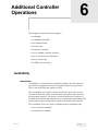
Chapter 6 — Additional Controller Operations
Availability. . . . . . . . . . . . . . . . . . . . . . . . . . . . . . . . . . . . . . . . . . . . . . . . . 6–1
Introduction . . . . . . . . . . . . . . . . . . . . . . . . . . . . . . . . . . . . . . . . . . . . 6–1
Availability Page . . . . . . . . . . . . . . . . . . . . . . . . . . . . . . . . . . . . . . . . 6–5
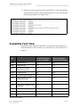
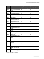
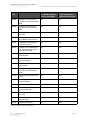
Availability Fault Table . . . . . . . . . . . . . . . . . . . . . . . . . . . . . . . . . . . . . 6–16
User Editable Fields . . . . . . . . . . . . . . . . . . . . . . . . . . . . . . . . . . . . . . . . 6–24
How to Change the Text and Date Fields . . . . . . . . . . . . . . . . . . 6–24
2
Rev AC
CLARiTY Laser Controller System Manual
Touch To Edit . . . . . . . . . . . . . . . . . . . . . . . . . . . . . . . . . . . . . . . . . . . . . 6–28
Production Audit Log . . . . . . . . . . . . . . . . . . . . . . . . . . . . . . . . . . . . . . 6–30
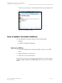
How to Update Controller Software . . . . . . . . . . . . . . . . . . . . . . . . . . 6–32
Updating by USB Key . . . . . . . . . . . . . . . . . . . . . . . . . . . . . . . . . . 6–32
Updating by CLARiTY Configuration Manager . . . . . . . . . . . . 6–33
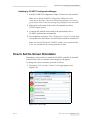
How to Set the Screen Orientation. . . . . . . . . . . . . . . . . . . . . . . . . . . . 6–33
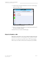
How to Create a Job . . . . . . . . . . . . . . . . . . . . . . . . . . . . . . . . . . . . . . . . 6–34
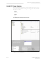
CLARiTY Power Saving . . . . . . . . . . . . . . . . . . . . . . . . . . . . . . . . . . . . 6–35
Chapter 7 — Maintenance
Replacement Instructions . . . . . . . . . . . . . . . . . . . . . . . . . . . . . . . . . . . . 7–1
Information on Care. . . . . . . . . . . . . . . . . . . . . . . . . . . . . . . . . . . . . . . . . 7–2
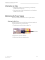
Maintaining the Power Supply . . . . . . . . . . . . . . . . . . . . . . . . . . . . . . . 7–2
Replacing the Mains Fuse . . . . . . . . . . . . . . . . . . . . . . . . . . . . . . . . 7–2
Maintaining the Controller . . . . . . . . . . . . . . . . . . . . . . . . . . . . . . . . . . . 7–3
Chapter 8 — Troubleshooting
Fault Messages and Warnings . . . . . . . . . . . . . . . . . . . . . . . . . . . . . . . . 8–1
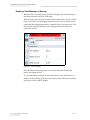
Reading a Fault Message or Warning . . . . . . . . . . . . . . . . . . . . . . 8–2
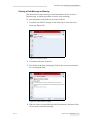
Clearing a Fault Message or Warning . . . . . . . . . . . . . . . . . . . . . . 8–3
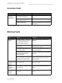
Controller Fault. . . . . . . . . . . . . . . . . . . . . . . . . . . . . . . . . . . . . . . . . . . . . 8–4
Marking Faults . . . . . . . . . . . . . . . . . . . . . . . . . . . . . . . . . . . . . . . . . . . . . 8–4
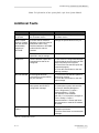
Additional Faults . . . . . . . . . . . . . . . . . . . . . . . . . . . . . . . . . . . . . . . . . . . 8–5
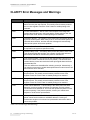
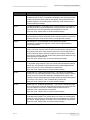
CLARiTY Error Messages and Warnings . . . . . . . . . . . . . . . . . . . . . . . 8–6
Diagnostics . . . . . . . . . . . . . . . . . . . . . . . . . . . . . . . . . . . . . . . . . . . . . . . 8–43
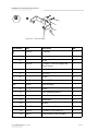
Chapter 9 — Illustrated Parts List
Standard Controller Assembly . . . . . . . . . . . . . . . . . . . . . . . . . . . . . . . . 9–1
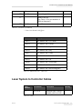
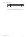
Laser System to Controller Cables . . . . . . . . . . . . . . . . . . . . . . . . . . . . . 9–3
Appendix A — Laser Products
Limitations. . . . . . . . . . . . . . . . . . . . . . . . . . . . . . . . . . . . . . . . . . . . . . . . A–1
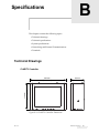
Appendix B — Specifications
Technical Drawings . . . . . . . . . . . . . . . . . . . . . . . . . . . . . . . . . . . . . . . . . B–1
CLARiTY Controller. . . . . . . . . . . . . . . . . . . . . . . . . . . . . . . . . . . . . B–1
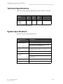
Technical Specifications. . . . . . . . . . . . . . . . . . . . . . . . . . . . . . . . . . . . . . B–2
System Specifications . . . . . . . . . . . . . . . . . . . . . . . . . . . . . . . . . . . . . . . . B–2
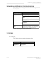
Networking and External Communications . . . . . . . . . . . . . . . . . . . . B–3
Rev AC
3
CLARiTY Laser Controller System Manual
Terminals . . . . . . . . . . . . . . . . . . . . . . . . . . . . . . . . . . . . . . . . . . . . . . . . . .B–3
Power Supply. . . . . . . . . . . . . . . . . . . . . . . . . . . . . . . . . . . . . . . . . . .B–3
Temperature and Humidity . . . . . . . . . . . . . . . . . . . . . . . . . . . . . .B–4
Environment . . . . . . . . . . . . . . . . . . . . . . . . . . . . . . . . . . . . . . . . . . .B–4
Appendix C — CLARiTY Configuration Manager
Introduction . . . . . . . . . . . . . . . . . . . . . . . . . . . . . . . . . . . . . . . . . . . . . . . C–1
CLARiTY Configuration Manager . . . . . . . . . . . . . . . . . . . . . . . . . . . . C–2
Glossary
4
Rev AC
1
Introduction
The CLARiTY Laser Controller is designed to operate the Videojet Laser
Coding and Marking systems using the CLARiTY operating system. The
user interface is easy to use and minimizes set up and fault finding time.
About the Manual
This System Manual is written for the every day user of the laser system.
The System Manual helps the user to understand the different parts and
different marking operations of the CLARiTY Laser Controller.
Related Publications
Please refer to the system manual(s) provided with the laser and coding
system. These documents contain safety, setup and operation information
for each laser system.
The following manuals are available for reference:
CLARiSOFT User Manual, Part Number: 462458
CLARiSUITE Web server User Manual, Part Number: 462459
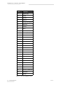
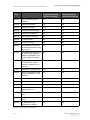
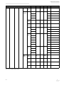
Language Codes
When you order this manual, make sure to add the 2-digit language code
at the end of the part number. For example, the Danish version of the
system manual is part number 462446-18. Table 1-1 on page 1-2 shows the
list of language codes that you can use to identify the translated versions
of this manual.
For more information, contact the Videojet distributor or subsidiary.
Rev AC
About the Manual
1-1
CLARiTY Laser Controller System Manual
Code
Language
01
English (US)
02
French
03
German
04
Spanish
05
Portuguese Brazilian
06
Japanese
07
Russian
08
Italian
09
Dutch
10
Chinese (Simplified)
11
Arabic
12
Korean
13
Thai
15
Norwegian
16
Finnish
17
Swedish
18
Danish
19
Greek
20
Hebrew
21
English (UK)
23
Polish
24
Turkish
25
Czech
26
Hungarian
33
Vietnamese
34
Bulgarian
36
Chinese (Traditional)
55
Romanian
57
Serbian
Table 1-1: List of Language Codes
1-2
Related Publications
Rev AC
CLARiTY Laser Controller System Manual
Content Presentation
This System Manual contains different types of information like safety
guidelines, additional notes, user interface (UI) terminology and so on. To
help you identify the different types of information, different writing
styles are used in this manual.
Positional References
Positions and directions like left, right, front, rear, to the right and to the
left are with respect to the controller when you see it from the front.
Units of Measurement
This manual uses metric units of measurement. The equivalent English
measures are included in parenthesis. For example, 240 mm (9.44 inches).
Safety Information
Specific safety information is listed throughout this manual in the form of
Warning and Caution statements. Pay close attention to these statements
as they contain important information that help in avoiding potential
hazards to yourself or to the equipment.
Warning
• The warning statements indicate hazards or unsafe practices that can
cause severe personal injury or death.
• They have a triangular symbol with an exclamation mark to the
immediate left of the text
• They are always preceded by the word “Warning”
• They are always found before the step or information referring to the
hazard
For example:
Warning
PERSONAL INJURY. All electrical wiring and connections must
comply with applicable local codes. Consult the appropriate
regulatory agency for further information.
Rev AC
Content Presentation
1-3
CLARiTY Laser Controller System Manual
Caution
• The caution statements indicate hazards or unsafe practices that result
in equipment or property damage
• They have a triangular symbol with an exclamation mark to the
immediate left of the text
• They are always preceded by the word “Caution”
• They are always found before the step or information referring to the
hazard
For example:
Caution
EQUIPMENT DAMAGE. Read this chapter thoroughly before
attempting to install, operate, service, or maintain this equipment.
Notes
Notes provide additional information about a particular topic.
For example:
Note: You can set the password protection for some functions to prevent any
access that is not authorised.
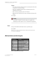
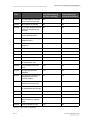
Abbreviations and Acronyms
Abbreviation
Expansion
AC
Alternating Current
AOS
Advanced Operating System
ASP
Analog Signal Processor
FPGA
Field Programmable Gate Array
LED
Light Emitting Diode
UI
User Interface
WYSIWYG
What You See Is What You Get
Table 1-2: Abbreviations and Acronyms
1-4
Abbreviations and Acronyms
Rev AC
CLARiTY Laser Controller System Manual
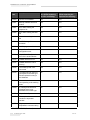
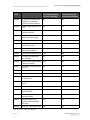
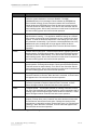
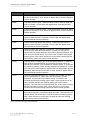
Chapters in the Manual
This manual is divided into twelve chapters. An introduction to the topics
that each chapter covers is shown in Table 1-3.
Chapter
No.
Chapter Name
Description
1.
Introduction
Contains the information about this manual, the main parts, the
related publications, and writing styles used in this manual.
2.
Safety
Contains the safety and hazard information.
3.
Installation
Contains the information about complete laser system, controller
connections, interconnecting cable and system setup.
4.
CLARiTY
Operating System
Contains the information about CLARiTY operating system and
updating CLARiTY operating system.
5.
Controller
Operation
Contains the information about starting and stopping the
controller, viewing and selecting a job for marking, line setup,
modifying and deleting a job from the jobs database.
6.
Additional
Controller
Operations
Contains the information about availability, touch to edit, quick
position edit, production audit log, set screen orientation and
CLARiTY power saving.
7.
Maintenance
Contains the information on replacement instructions, service,
and maintenance.
8.
Troubleshooting
Contains the operator level diagnostic and troubleshooting
procedures.
9.
IPL
Contains the illustrated parts list of orderable parts.
10.
Appendix A
Contains the information about different laser products.
11.
Appendix B
Contains CLARiTY Laser Controller specifications.
12.
Appendix C
Contains information about CLARiTY Configuration Manager.
Table 1-3: List of Chapters
Rev AC
Chapters in the Manual
1-5
2
Safety
This chapter contains the following topics:
• Introduction
• Equipment safety guidelines
• Placement of the controller
• Medical emergencies
Caution
EQUIPMENT DAMAGE. Read this chapter thoroughly before
attempting to install, operate, service, or maintain this equipment.
Warning
EQUIPMENT DAMAGE. This safety chapter covers the controller
safety requirements. Please make sure to read the Laser System
Manual safety warnings before operating the laser system.
Warning
PERSONAL INJURY. Follow the installation and operating
instructions at all times. Only trained personnel should carry out
maintenance or repair. Use of this equipment for any other purposes
other than its intended use may lead to serious personal injury.
Rev AC
2-1
CLARiTY Laser Controller System Manual
Introduction
The policy of Videojet Technologies Inc. is to manufacture non-contact
coding systems that meet high standards of performance and reliability.
Therefore, we employ strict quality control techniques to eliminate the
potential for defects and hazards in our products.
The safety guidelines provided in this chapter are intended to educate the
operator on all safety issues so that the operator can operate the laser
system safely.
Equipment Safety Guidelines
This section contains important safety guidelines pertaining to the
operation and handling of the controller and associated equipment.
Warning
PERSONAL INJURY. While performing maintenance or repair
work, disconnect the mains supply unless it is absolutely necessary
to leave the supply on while carrying out adjustments.
Comply with Electrical Codes
Warning
PERSONAL INJURY. All electrical wiring and connections must
comply with applicable local codes. Consult the appropriate
regulatory agency for further information.
Electrical Power
Warning
PERSONAL INJURY. This equipment must be installed with a
locally positioned mains supply isolation device. This can be either a
plug and socket or a switch connector or circuit breaker in
accordance with IEC 60947-3 or IEC 60947-2.
2-2
Introduction
Rev AC
CLARiTY Laser Controller System Manual
Warning
PERSONAL INJURY. Ensure that all external energy sources, mains
and mains power connector are isolated from equipment. This
should be done before attempting any maintenance or repair on any
part of the product.
Warning
PERSONAL INJURY. Ensure that any cables from the controller are
secured to avoid chance of movement into walkways and becoming
a trip hazard.
Warning
PERSONAL INJURY. There will be sections of the Printed Circuit
Board (PCB) that will be permanently powered via the on-board
lithium battery - therefore it is essential that the board should never
be placed onto, nor stored in or on any conductive surface (including
conductive, plastic bags etc.) as this would flatten the battery and/or
potentially result in battery overheating. The battery is not to be
replaced by the operator.
Do Not Remove Warning Label
Warning
PERSONAL INJURY. Do not, under any circumstances, remove or
obstruct any warning, caution, or instruction labels present on the
controller. If any part of these labels become damaged, worn or
removed they must be immediately replaced.
Rev AC
Equipment Safety Guidelines
2-3
CLARiTY Laser Controller System Manual
Grounding and Bonding
Warning
PERSONAL INJURY. Always prevent static discharge from
occurring. Use proper Grounding and Bonding methods. Always
bond conductive equipment together with approved cables to
maintain them at the same potential and minimize static discharge.
Only use videojet approved metallic service trays and ground
cables.
Communications
Caution
EQUIPMENT DAMAGE. Ensure that all Ethernet/communication
cables are shielded (STP Cat5).
Placement of the Controller
Warning
PERSONAL INJURY. Do not place the controller in a hazardous
location. Hazardous locations might cause an explosion, leading to
personal injury. You must ensure compliance with all local
regulations regarding equipment placement in potentially
hazardous locations.
2-4
Placement of the Controller
Rev AC
CLARiTY Laser Controller System Manual
Medical Emergencies
This section provides important medical information in case of an
accident.
Warning
PERSONAL INJURY. In the event of a medical emergency, contact a
physician immediately.
Rev AC
Medical Emergencies
2-5
3
Installation
This chapter contains the following topics:
• Unpack and Inspect the Laser System and the Controller
• The Complete Laser System
• CLARiTY Laser Controller Connections
• How to Connect the Laser Marking System to the CLARiTY Laser
Controller
•QMark Version 8.5.3.2.1 or later required
• How to Setup the System
Unpack and Inspect the Laser System and the
Controller
Note: For information on unpacking the laser system, refer Laser System
Manual.
1 Open the shipping box, and make sure that all the parts listed in the
packing list are present in the box. If any part is missing, contact
Videojet Technologies Inc.
• Refer to Chapter, “Support and Training” for Videojet contact
information.
• Refer to Chapter, “Illustrated Parts List” for part numbers.
2 Make sure that there are no damaged parts. If you find any damaged
part, contact Videojet Technologies Inc. to order a new part.
Rev AC
Unpack and Inspect the Laser System and the Controller
3-1
CLARiTY Laser Controller System Manual
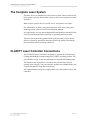
The Complete Laser System
The laser device is classified as a class 4 laser system. However the closed
laser system, up to the beam outlet, acts as a class 1 laser system in normal
operation.
Note: Normal operation does not include service, maintenance and repairs.
For information on safety, setup and operation of the laser coding and
marking system, refer to relevant Laser System Manual.
It is important to review and understand the information contained in the
Laser System Manual before installing or operating the laser system.
The laser system must be operated with open laser and/or open beam
delivery system by specially trained personnel only. Make sure that the
laser protection rules are always observed.
CLARiTY Laser Controller Connections
The CLARiTY Laser Controller is designed to operate the Videojet Laser
Coding and Marking systems using the CLARiTY operating system. The
user interface is easy to use and minimizes set up and fault finding time.
The stainless steel controller is a touch screen user interface with an
internal power supply. You can load jobs, modify user editable fields, and
set print parameters using the touch screen.
All communication and power supply cables are connected directly to the
controller.
3-2
The Complete Laser System
Rev AC
CLARiTY Laser Controller System Manual
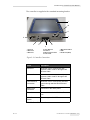
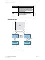
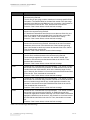
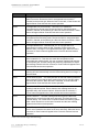
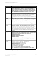
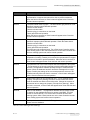
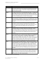
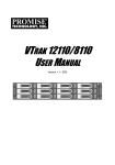
The controller is supplied with a standard mounting bracket.
1
2
3
4
9
8
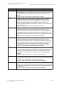
1. Touch UI
2. Ethernet 2
3. Ethernet 1
7
5
6
4. Laser Ethernet
Connection
5. Mains Lead Connector
6. Fuse Holder
7. Main Power Switch
8. USB
9. Serial Port (IOIOI)
Figure 3-1: Controller Connections
Ports
Description
Ethernet 1
Allows the user to communicate with
corporate LAN or local PC through RJ45
Ethernet Cable.
Ethernet 2
Allows the user to communicate with
corporate LAN or local PC through RJ45
Ethernet Cable
Laser Ethernet
Connection
Allows the user to communicate with laser
system through standard RJ45 Ethernet
Cable
Mains Lead
Connector
Connection to the mains power
Fuse Holder
Threaded holder for the AC Mains Power
fuse
Main Power
Switch
Turns the system ON/OFF
Table 3-1: Controller Connections
Rev AC
CLARiTY Laser Controller Connections
3-3
CLARiTY Laser Controller System Manual
Ports
Description
USB
USB Port that allows the connection of a
USB memory stick for functions such as
laser system software updates, transferring
Jobs and backup/restore of laser system
archive or clone files
Serial Port
(IOIOI)
RS-232 Serial Port for connecting to PC,
PLC or other capable device (special
adapter cable required)
Table 3-1: Controller Connections
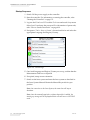
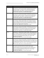
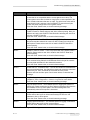
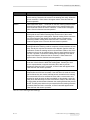
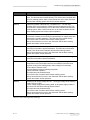
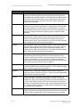
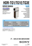
Interconnecting Cable
Mains
power
Standard IEC region
Specific power cord
Laser Printer +
power supply
CLARiTY Controller +
power supply
Ethernet Cable
RJ45 Ethernet
Cable*
Photocell/Encoder/
Addional I/O
Corporate LAN
* - Optional
Figure 3-2: Interconnecting Cable
3-4
CLARiTY Laser Controller Connections
Rev AC
CLARiTY Laser Controller System Manual
How to Connect the Laser Marking System to the
CLARiTY Laser Controller
To connect laser marking system to CLARiTY laser controller, proceed as
follows:
1 Assemble and install the laser marking system according to the
instructions provided in the Laser System Manual.
2 Setup the working distance according to the instructions provided in
the Laser System Manual.
3 Mount the CLARiTY laser controller as required in proximity to the
laser marking system.
4 Connect the controller to the laser marking system through the cable
provided
a. RJ45-RJ45
b. RJ45-8pin
Note: The connecting cable is dependent on the laser system available.
5 Ensure that product detector and/or encoder, if required, are
connected to the laser marking system.
6 Connect the controller and the laser marking system to the mains
supply.
The connection of laser marking system to the CLARiTY laser controller is
complete.
How to Setup the System
Once the connections are made, you need to setup the system for marking.
Prerequisites
Before you start the system, confirm the following:
• The manual keyswitch is in OFF position (where manual keyswitch is
available).
• Set the local electrical isolator switch for the laser system to ON
position.
• Laser Messages are in CIFF format. Existing laser messages can be
converted to CLARiTY CIFF files using the CIFF converter. See the
CIFF Converter Instruction (P/N 468427-01) for additional
information.
Rev AC
How to Connect the Laser Marking System to the CLARiTY Laser Controller
3-5
CLARiTY Laser Controller System Manual
Startup Sequence
1 Switch ON the power supply to the controller.
2 Start the controller. For information on starting the controller, refer
“Starting the Controller” on page 5-2.
3 Log into the UI at Level 2. Touch the Tools icon and touch Setup menu.
Select Level 2 and enter the password. For information of passwords,
refer “How to Set the Passwords” on page 4-19.
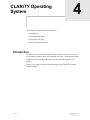
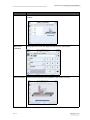
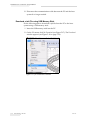
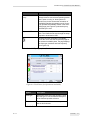
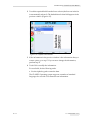
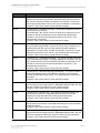
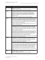
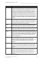
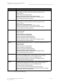
4 Navigate to Tools > Setup > Control > Internationalisation and select the
appropriate Language and Region/Country.
Figure 3-3: Control Page
5 Once both Language and Region/Country are set up, confirm that the
Measurement Units are as required.
6 If required, setup screen orientation.
7 Switch on the laser system and start the laser system as described in
the Laser System Manual. Retain the Manual Keyswitch in open
position.
Note: On connection to the Laser System, the status bar will stay at
shutdown.
Note: Once the manual keyswitch or software keyswitch is enabled, the
starting up message will be displayed and the unit will move to OFFLINE
mode.
3-6
How to Setup the System
Rev AC
CLARiTY Laser Controller System Manual
8 Confirm that the laser system and controller are connected. When the
units are connected, the 'Printhead Not Present' note on the home
screen disappears.
Note: Warning E10517 appears. Clear the warning by selecting the status
bar and following the instructions.
Note: If the units do not connect after a short period of time, refer to the
troubleshooting section “Printhead Absent” on page 8-5.
9 Navigate to Tools > Setup > Control > Date and Time to setup the correct
date and time.
10 Perform the line setup. For information on line setup, refer “Line
Setup” on page 5-11.
Note: Always make sure that the Line Set up on the controller is as per the
requirement of the PRODUCTION line. This is important especially in
situations where the controller is connected to the laser which was set up
using a different means or if the Laser is being replaced or when the laser is
not connected to a line.
11 Adjust the print position as required. For information on print
position, refer “Print Position” on page 5-4.
12 Select a job and start the laser marking. For information on selecting a
job and starting the marking, refer “Selecting a Job for Marking” on
page 5-3 and “Starting the Laser Marking” on page 5-23 respectively.
Note: If the job is not downloaded correctly, refer to “Job Download Failure”
on page 8-5.
Note: Before marking, follow the safety instructions as mentioned in the
Laser System Manual.
Rev AC
How to Setup the System
3-7
CLARiTY Operating
System
4
This chapter contains the following topics:
• Introduction
• Using the home page
• Using the tools page
• How to set the passwords
Introduction
CLARiTY is an icon-based operator control system. It has an easy-to-use
touch screen and most areas of the display are active. All technical aspects
of the laser system setup and control are accessed through the Tools
button.
Figure 4-1 on page 4-2 shows the home page of the CLARiTY operator
control system.
Rev AC
Introduction
4-1
CLARiTY Laser Controller System Manual
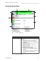
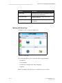
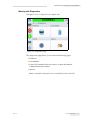
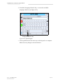
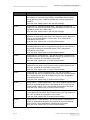
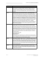
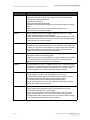
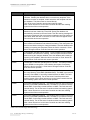
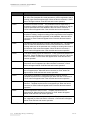
Using the Home Page
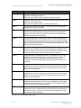
8
1
2
7
3
6
4
5
1. Controller Status Bar
2. Tools Button
3. Current Job Details Bar
4. Performance Information
5. Print Position
6. System Control Buttons
7. Home Button
8. Job Select Button
Figure 4-1: CLARiTY Home Page
Button
Description
Controller Status Bar
Provides information about the status of the
controller:
• Starting Up- Controller unit establishing
communication with the laser marking and
coding system.
• Shutdown- Laser system is turned on and the
keyswitch is disabled.
• Offline- Laser system is turned on and
keyswitch is enabled.
• Running- Laser system is turned on and
marking. Keyswitch is enabled.
• Allows the user to enable/disable marking as
requested.
• If warnings or faults are present, it allows the
user to access and review them when
selected.
Table 4-1: Home Screen Buttons
4-2
Using the Home Page
Rev AC
CLARiTY Laser Controller System Manual
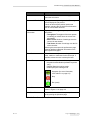
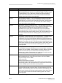
Button
Description
Tools Button
Allows the user to access the Tools page and
opens the tools menu.
Current Job Details Bar
Displays the actual job being marked. Selecting the
bar will display the job preview.
If touch to edit and print position options are
enabled, selecting the job detail bar will allow the
user to access these functions.
Performance
Information
Displays the following laser system performance
information:
• Throughput: Throughput of the laser system
in marking per minute since the current Job
was loaded.
• Batch Count: Number of markings since the
current Job was loaded.
• Total Count: Number of markings over the life
of the controller.
Selecting this area opens the performance page
showing additional statistical information on the
laser system throughput.
Print Position
Allows the user to adjust the marking position,
scale, rotation or mark sets for the current job. If
available, allows the user to select pilot laser.
Control Buttons
Allows the user to perform the following actions:
• Keyswitch enable/disable (software keyswitch
only).
• Disable (Stop) the marking mode.
• Enable (Run) the marking mode.
Keyswitch (for more information,
refer Table 4-2 on page 4-4)
Stop
Run (mark)
Home Button
Allows the user to access the Home screen as
shown in Figure 4-1 on page 4-2.
Job Select Button
Allows the user to select the required job from the
list by opening the job select page.
Table 4-1: Home Screen Buttons (Continued)
Rev AC
Using the Home Page
4-3
CLARiTY Laser Controller System Manual
Icon
Description
Manual keyswitch - closed
Manual keyswitch - opened
Software keyswitch - disabled
Software keyswitch - enabled
Table 4-2: Keyswitch Icons
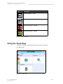
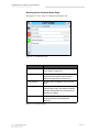
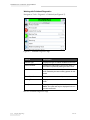
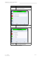
Using the Tools Page
Touch the Tools icon on the home page to access the tools page
(see Figure 4-2).
Figure 4-2: Tools Page
4-4
Using the Tools Page
Rev AC
CLARiTY Laser Controller System Manual
Buttons
Description
Setup Page
Permits the user to modify a small subset of the
laser system setup parameters.
Diagnostics Page
Provides on-line fault finding routines and
diagnostic functions.
Databases page
Provides control over the jobs database of the
laser system.
Table 4-3: Tools Page
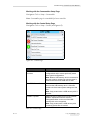
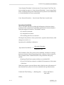
Working with Setup Page
Navigate to Tools > Setup (see Figure 4-3).
Figure 4-3: Setup Page
The Setup page allows you to access the following parameters:
• Printhead
• Consumables
• Control (for example, time, date, language)
• Options
Note: Consumables and Options are not available for Laser controller.
Rev AC
Using the Tools Page
4-5
CLARiTY Laser Controller System Manual
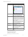
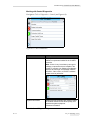
Working with the Printhead Setup Page
Navigate to Tools > Setup > Printhead (see Figure 4-4).
Figure 4-4: Printhead Setting
Buttons
Description
Line Setup
For information on Line Setup Wizard refer
“Line Setup” on page 5-11
Lens Type
Shows a list of available lens types for the
connected laser system when selected.
Select the required lens from the list.
Focal Distance
Displays the focal distance of the selected
lens.
Working Distance
Displays the working distance for the
selected lens, that is, the distance at which
the laser head needs to be mounted to the
product for marking
Pilot Laser
If the pilot laser is available, allows the user
to set up the laser as needed when
selected.
Table 4-4: Printhead Setting
4-6
Using the Tools Page
Rev AC
CLARiTY Laser Controller System Manual
Working with the Consumables Setup Page
Navigate to Tools > Setup > Consumables.
Note: Consumables page is not available for Laser controller.
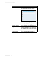
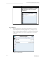
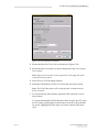
Working with the Control Setup Page
Navigate to Tools > Setup > Control (see Figure 4-5).
Figure 4-5: Control Page
Buttons
Description
CLARiTY Parameters
Archives
Allows the user to save current laser system
configurations and to restore previously saved
laser system configurations.
Note: When a USB memory stick is connected to
the laser system, archives can also be saved or
restored to and from the USB drive as well.
CLARiTY Printer Clones
Allows the user to create or restore a Clone file to
and from the USB memory stick. A Clone file
contains all of the laser system settings and Job
files.
Note: Only present when a USB memory stick is
inserted.
CLARiTY Update
Allows the user to select from a list of available
updates. Update files must be saved in
clarityupdate folder on the root of the USB
memory stick to be recognized.
Note: Only present when a USB memory stick
containing update files is inserted.
Table 4-5: Control Page
Rev AC
Using the Tools Page
4-7
CLARiTY Laser Controller System Manual
Buttons
Description
Set Screen Orientation
Allows the user to change the screen orientation
by selecting ‘0’ or ‘180’ degrees, as required.
Internationalisation
Allows the user to set the language of the
CLARiTY screen, the international region/country
which control the date/time formats and
measurement units displayed within CLARiTY.
Recalibrate Touchscreen
Allows the user to recalibrate the touchscreen, if
touching the screen does not accurately locate the
correct CLARiTY button or Icon. The laser system
requests the user to touch several crosses which
are displayed on the screen, one after the other.
The screen is recalibrated when the automated
process is complete.
Note: If the calibration of the machine has too
many errors and does not allow a user to navigate
to this screen via the CLARiTY panel, the same
functionality can be triggered from within
CLARiTY Configuration manager.
Date and Time
Allows the user to set the system date and time of
the laser system.
Communications
Allows the user to reset all communication ports to
factory default settings if corrupted. These default
settings configure the laser system to
communicate with CLARiSOFT® and CLARiTY
Configuration Manager.
Contact Information
Allows the user to enter the laser system location
address.
Table 4-5: Control Page (Continued)
Working with the Option Setup Page
Navigate to Tools > Setup > Option.
Note: Options page is not available for Laser controller.
4-8
Using the Tools Page
Rev AC
CLARiTY Laser Controller System Manual
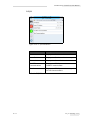
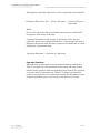
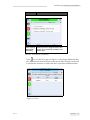
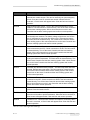
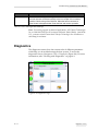
Working with Diagnostics
Navigate to Tools > Diagnostics (see Figure 4-6).
Figure 4-6: Diagnostics Page
The diagnostics page allows you to access the following pages:
• Printhead
• Consumables
• Control (for example software versions, system information,
communications port status)
• Options
Note: Consumables and Options are not available for Laser controller.
Rev AC
Using the Tools Page
4-9
CLARiTY Laser Controller System Manual
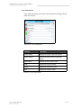
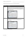
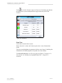
Working with Printhead Diagnostics
Navigate to Tools > Diagnostics > Printhead (see Figure 4-7).
Figure 4-7: Printhead Diagnostics Page
Buttons
Description
Scanner Type
Displays the type of scanner installed on the laser.
Product Counter
Displays the total product count for this batch i.e.,
the number of products passing the laser coder.
Print Counter
Displays the total number of products that have
been marked by the laser marking system for this
batch.
Global Print Counter
Displays the total number of products marked.
Marking Time
Displays the time the laser beam is ON for one
mark.
Line Speed
Displays the speed of production line.
Note: This option will only be displayed if there is
product movement.
Table 4-6: Printhead Diagnostics Page
4-10
Using the Tools Page
Rev AC
CLARiTY Laser Controller System Manual
Buttons
Description
Event Log
Contains the log of events, faults and warnings
over a total period of 180 days. Allows the user to
select a fault or warning event on the screen for
further information.
Also allows the user to hide various events (such
as faults or warnings) and export the information
to USB as required.
For more information, refer to “Event Time” on
page 6-10
Inputs
Refer to “Inputs” on page 4-12.
Relative Operating Hours
Displays the operating hours since the last service
operation was reset.
Absolute Operating Hours
Displays the total number of hours laser system is
in operation.
Laser System State
Displays the current Laser system status.
Table 4-6: Printhead Diagnostics Page (Continued)
Rev AC
Using the Tools Page
4-11
CLARiTY Laser Controller System Manual
Inputs
It displays information about various inputs from the laser
(see Figure 4-8).
Figure 4-8: Printhead Inputs Diagnostics Page
Buttons
Description
Laser Clock
Displays the current date and time from the laser
marking system.
Trigger Detector Attached
Indicates if the trigger detector is present (TRUE).
Encoder Attached
Indicates if the encoder is present (TRUE).
UI 24 Volts Supply
Displays the instantaneous voltage of the
controller 24 V supply.
UI PCB Temperature
Displays the PCB temperature information.
Table 4-7: Printhead Inputs Diagnostics Page
4-12
Using the Tools Page
Rev AC
CLARiTY Laser Controller System Manual
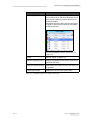
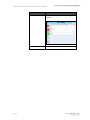
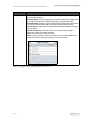
Working with Control Diagnostics
Navigate to Tools > Diagnostics > Control (see Figure 4-9).
Figure 4-9: Control Parameters
Buttons
Description
Versions
Displays the software versions of the various
software components installed in the CLARiTY
controller.
Note: If there is any inconsistency among the
software components that are installed in the
CLARiTY controller, the Software Part Number
displays the message 'Incompatible Software
Versions'. If this is seen, a CLARiTY software
update must be performed.
System Information
Displays the serial number and revision number
of controller Printed Circuit Board (PCB), CPU
speed and system equipment
reference information.
Table 4-8: Control Diagnostics Page
Rev AC
Using the Tools Page
4-13
CLARiTY Laser Controller System Manual
Buttons
Description
Communications
Touch Communications on the Control dialog
box. Communications dialog box appears.
TCP/IP: Displays the configuration and status of
the laser system’s network port. For more
information, see “TCP/IP” on page 4-15.
Production Audit Log
Refer to “Production Audit Log” on page 6-30.
Image Update Queue
Displays all Jobs currently in the laser system's
queue, and the number of times each Job has
been allocated to print. “No Print Limit” indicates
that the currently loaded Job will continue to
print until a new Job is loaded.
Laser Information
Refer to “Laser Information” on page 4-16.
Table 4-8: Control Diagnostics Page (Continued)
4-14
Using the Tools Page
Rev AC
CLARiTY Laser Controller System Manual
TCP/IP
Figure 4-10: TCP/IP Parameters
Buttons
Description
IP Address
Displays the IP Address of the controller
Laser IP Address
Displays the IP Address of the Laser system
Subnet Mask
Displays the Subnet Mask number
CLARiTY
Communications
Displays the TCP/IP port number and
CLARiTY network status.
Text Communications
Displays the TCP/IP port number assigned
for Text Communications.
Table 4-9: TCP/IP Parameters
Rev AC
Using the Tools Page
4-15
CLARiTY Laser Controller System Manual
Laser Information
It provides information about the laser system used along with the
software versions.
Figure 4-11: Laser Information
Buttons
Description
Printer Model
Displays the model of the laser system
Serial Number
Displays the serial number of the laser
system
Laser Name
Displays the laser system name
AOS
Displays the version of AOS
FPGA
Displays the version of FPGA
ASP
Displays the version of ASP
Table 4-10: Laser Information
4-16
Using the Tools Page
Rev AC
CLARiTY Laser Controller System Manual
Buttons
Description
FM
When selected, displays the following
screen:
QMark
Displays the version of QMark
Table 4-10: Laser Information (Continued)
Rev AC
Using the Tools Page
4-17
CLARiTY Laser Controller System Manual
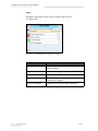
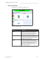
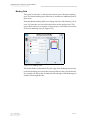
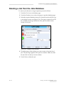
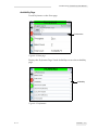
Working with Database
Navigate to Tools > Databases (see Figure 4-12).
Figure 4-12: Database Page
Buttons
Description
Internal
Shows the job stored in the laser system and
allows the user to transfer Jobs to the USB
memory stick (if available). The user is also able
to delete Jobs from the Internal database.
Capacity
Shows the estimated number of Job files that
could be stored on the printer, based on the size
of existing Job files, and the number of bytes of
available Job storage remaining.
External
Shows the Jobs stored on the inserted USB
memory stick, and allows the user to transfer Jobs
to the Internal database. The user is also able to
delete Jobs from the USB memory stick.
Note: Option only available when USB memory
stick is inserted in printer.
Table 4-11: Database Page
4-18
Using the Tools Page
Rev AC
CLARiTY Laser Controller System Manual
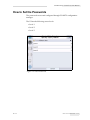
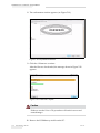
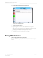
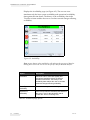
How to Set the Passwords
The passwords are set and configured through CLARiTY configuration
manager.
The UI has the following access levels:
• Level 1
• Level 2
• Level 3
Figure 4-13: Password Levels
Rev AC
How to Set the Passwords
4-19
CLARiTY Laser Controller System Manual
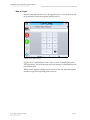
How to Login
When a menu requires the user to be logged in above Level 0, the user will
be prompted to select the required password level.
Figure 4-14: Select Level
Login at level 1 (default password = 1111) or level 2 (default password =
2222) password. The current password level changes to selected password
level from level 0.
Where access requires a higher password level, the user must first logout
and then login at the required password level.
4-20
How to Set the Passwords
Rev AC
CLARiTY Laser Controller System Manual
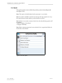
Only those functions available at the logged in password level will be
visible to the user. If there are no options available to the user at that
password level, a message will be displayed (see Figure 4-15).
Figure 4-15: Access Denied
Rev AC
How to Set the Passwords
4-21
CLARiTY Laser Controller System Manual
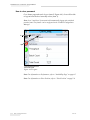
How to clear password
Go to home page and touch Logout (item 2, Figure 4-16). You will be able
to logout from the level currently active (item 1).
Note: Level 1 and Level 2 passwords will automatically logout after a default
period of time. This feature can be configured in the CLARiTY Configuration
Manager.
2
1
1. Current Password Level
2. Touch to logout
Figure 4-16: Logout
Note: For information on Performance, refer to “Availability Page” on page 6-5.
Note: For information on Print Position, refer to “Print Position” on page 5-4.
4-22
How to Set the Passwords
Rev AC
Controller Operation
5
This chapter contains the following topics:
• Starting the Controller
• Selecting a Job for Marking
• Print Position
• Line Setup
• Starting the Laser Marking
• Stopping the Marking
• Viewing the Current Job or Image
• Downloading a job file
• Deleting a job from the jobs database
• Turning Off the Controller
Rev AC
5-1
CLARiTY Laser Controller System Manual
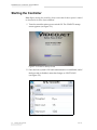
Starting the Controller
Note: Before starting the controller, please ensure that the laser system is started
as described in the Laser System Manual.
1 Turn the controller mains power switch ON. The CLARiTY startup
screen appears (see Figure 5-1).
Figure 5-1: CLARiTY Startup Screen
2 Once the laser system is ON and communication is established, and if
the keyswitch is disabled, status bar changes to SHUTDOWN
(see Figure 5-2).
Figure 5-2: Laser System ON
5-2
Starting the Controller
Rev AC
CLARiTY Laser Controller System Manual
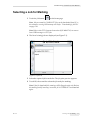
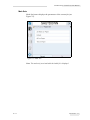
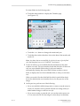
Selecting a Job for Marking
3 Touch the Job button
on the home page.
Note: Jobs are created in CLARiSOFT. Jobs can be downloaded from PC to
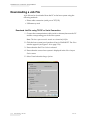
the controller or using USB memory stick. Refer “Downloading a Job File”
on page 5-26.
Note: Refer to the CIFF Converter Instruction (P/N 468427-01) to convert
Laser XML messages to CIFF jobs.
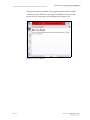
4 The list of existing jobs are displayed (see Figure 5-3).
Figure 5-3: Job List
5 Select the required job from the list. The job print preview appears.
6 Touch OK, the controller selects the job ready for marking.
Note: If the job download fails, warnings will be flagged on the unit. Review
the warnings and if necessary, correct the job in CLARiSOFT and download
again.
Rev AC
Selecting a Job for Marking
5-3
CLARiTY Laser Controller System Manual
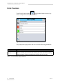
Print Position
Touch Print Position button
at the left hand bottom side of any
screen to adjust the current job parameters.
Figure 5-4: Print Position Screen
The print position page allows the user to set the following parameters:
Parameter
Description
Laser Beam
Source
The user can select the beam source as pilot laser or marking laser. The pilot
laser, if available, when selected will show the path of the job, without marking,
when job started. Selecting marking laser will allow the laser to mark.
Table 5-1: Print Position Page parameters
5-4
Print Position
Rev AC
CLARiTY Laser Controller System Manual
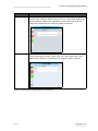
Parameter
Description
Position
The Offset X and Offset Y adjustment buttons allows the user to move the
position of the marking in either or both of the X or Y axis in both negative and
positive direction. Position (0,0) indicates the centre of the marking or lens.
Select one or both buttons to modify the position as required.
Scale
The Scale X and Scale Y buttons allows the user to increase or decrease the
scale of the marking in either or both of the X or Y axis. Scale ‘100%’ is the
default value. Select one or both buttons to modify the scale as required.
Table 5-1: Print Position Page parameters (Continued)
Rev AC
Print Position
5-5
CLARiTY Laser Controller System Manual
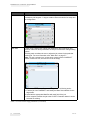
Parameter
Description
Rotation
The rotation button allows the user to rotate the job in clockwise or counterclockwise by 360 degrees. ‘0’ degree rotation relates to both the line setup and
job configuration.
Mark Sets
A mark set is a specific set of laser print parameters where maximum and
minimum values for these parameters are unique to each laser coding/marking
system.
Selecting mark set allows the user to adjust the job values for the particular
marking job. For more information refer “Mark Sets” on page 5-7.
Note: If no job is selected or a job has been created outside CLARiSOFT
without a valid mark set, the mark set list will be empty.
If a job does not have a mark set available, perform the following action:
1. Load the job into CLARiSOFT and identify the Mark Sets available for the
target laser.
2. Associate the appropriate Mark Set with each field of the job.
3. Once complete, transfer the job to the CLARiTY Controller where it can be
selected for marking.
Table 5-1: Print Position Page parameters (Continued)
5-6
Print Position
Rev AC
CLARiTY Laser Controller System Manual
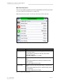
Mark Sets
Mark Sets button displays the parameters of the current job (see
Figure 5-5).
Figure 5-5: Mark Sets
Note: The mark set(s) associated with the loaded job is displayed.
Rev AC
Print Position
5-7
CLARiTY Laser Controller System Manual
Mark Sets Parameters
The set of available parameters for the selected Mark Set will be presented
as a list of buttons (see Figure 5-6 on page 5-8).
Note: If the laser key switch is closed, then the buttons will be read only.
Figure 5-6: Mark Sets Parameters
Buttons
Description
Marking Speed
Allows the user to enter the marking speed in millimeter
per second (mm/s).
It is the speed of movement of the laser beam when
marking the product.
This value ranges from 1 to 30000.
Mark Delay
Allows the user to enter the mark delay in microseconds
(µs).
It is the delay between the marking of individual vectors
within a stroke.
This value ranges from 0 to 999.
Stroke Delay
Allows the user to enter the stroke delay in microseconds
(µs).
It is the delay between the end of a stroke and the jump to
the next stroke.
This value ranges from 0 to 2000.
Table 5-2: Mark Sets parameters
5-8
Print Position
Rev AC
CLARiTY Laser Controller System Manual
Buttons
Description
Jump Speed
Allows the user to enter the jump speed in millimeter per
second (mm/s).
It is the speed of movement of the laser beam when
moving from one stroke to the next. The laser is switched
off during a jump.
This value ranges from 500 to 40000.
Jump Delay
Allows the user to enter the jump delay in microseconds
(µs).
It is the delay between the end of a jump and the start of
the marking process.
This value ranges from 0 to 5000.
Mark Intensity
Allows the user to enter the mark intensity in percentage
(%).
It is the output Mark Intensity through the current value
(with 100% corresponding to the maximum Mark Intensity
of the laser).
This value ranges from 0 to 100.
Laser On Delay
Allows the user to enter the laser on delay in
microseconds (µs).
It is the delay between the attainment of the start position
of a stroke and the switching-on of the laser.
This value ranges from X to 1000.
Where X = (20 - Jump Delay) >= (-1000)
Laser Off Delay
Allows the user to enter the laser off delay in
microseconds (µs).
It is the delay between the attainment of the end position of
a stroke and the switching-off of the laser.
This value ranges from 0 to 1000.
Table 5-2: Mark Sets parameters (Continued)
Rev AC
Print Position
5-9
CLARiTY Laser Controller System Manual
Data Entry
If a mark sets parameter button is selected, it displays a Data Entry screen
(see Figure 5-7) showing the current value and the permitted range (max
and min) that the input value takes.
If you modify a parameter by selecting the OK button on the Data Entry
screen, the new value is stored in the CLARiTY parameter and is
automatically sent to the Laser.
Figure 5-7: Data Entry
Completion
When you navigate away from Mark Sets Parameters screen, you will be
prompted to either save or discard the changes made to the parameters.
Note: The changes to mark sets will be saved for the job until it is removed or
reloaded into the controller.
5-10
Print Position
Rev AC
CLARiTY Laser Controller System Manual
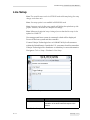
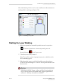
Line Setup
Note: The controller must not be in OFFLINE mode while transferring line setup
changes to the laser unit.
Note: Line setup option is not available in RUNNING mode.
Note: On power cycle, the line setup graphic will display the equivalent top side
graphic. However, the actual line setup will not change.
Note: Whenever the physical setup is changed, ensure that the line setup is also
updated on CLARiTY.
If an unsupported laser system is connected, a fault will be displayed.
Power off the laser system and the controller.
Contact Videojet Technologies Inc. at 1-800-843-3610 (for all customers
within the United States). Outside the U.S., customers should contact their
Videojet Technologies Inc. distributor or subsidiary for more information.
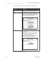
Navigate to Tools > Setup > Printhead > Line Setup.
Figure 5-8: Line Setup
Buttons
Description
Position and Orientation
Allows the user to adjust the position and
orientation of the laser head with respect to the
product.
Table 5-3: Line Setup Buttons
Rev AC
Line Setup
5-11
CLARiTY Laser Controller System Manual
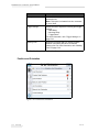
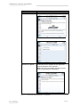
Buttons
Description
Line Speed
Allows the user to adjust the speed of the
production line.
Note: This option is disabled if the line movement
is set to Static.
Trigger Settings
Allows the user to adjust the following print trigger
settings:
• Start Delay
• Blocking Delay
• Trigger Mode
For more information, refer “Trigger Settings” on
page 5-19.
Marking Field
Defines the marking field size. Allows to switch
between full marking field and user defined
marking field. For more information, refer “Marking
Field” on page 5-22.
Table 5-3: Line Setup Buttons (Continued)
Position and Orientation
Figure 5-9: Position and Orientation
5-12
Line Setup
Rev AC
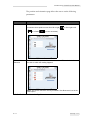
CLARiTY Laser Controller System Manual
The position and orientation page allows the user to set the following
parameters:
Parameter
Description
Line Movement
Allows the user to set the direction of Job relative to the laser head. Select line
movement where product moves from left to right
or is Static
Product Side
Selection
or from right to left
(no line movement).
Sets the side of the product that needs to be marked. The red color indicates
the side on which the marking happens.
Note: The last two selections are only available if Line Movement is set to the
Static option.
Table 5-4: Position and Orientation Page Parameters
Rev AC
Line Setup
5-13
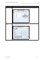
CLARiTY Laser Controller System Manual
Parameter
Description
Laser Position
Allows the user to select the graphic from the four orientations available.
Manual Laser
Position
Allows the user to enter the angle precisely from 0 to 359 degrees.
Table 5-4: Position and Orientation Page Parameters (Continued)
5-14
Line Setup
Rev AC
CLARiTY Laser Controller System Manual
Parameter
Description
Job Orientation
Allows the user to select the orientation of the marking with respect to the
product.
Manual Job
Orientation
Allows the user to enter the angle precisely from 0 to 359 degrees.
Current Settings
Screen shows the graphic representation of the current line setup.
Table 5-4: Position and Orientation Page Parameters (Continued)
Rev AC
Line Setup
5-15
CLARiTY Laser Controller System Manual
Line Speed
This option sets the rate at which the product passes the marking head
(see Figure 5-10).
Note: This option is disabled when the line movement is set to Static.
Note: A wizard is available to take the user through the steps required to set up
line speed when an encoder and/or a product detector are fitted.
Note: If there is no encoder connected to the laser, then the following options will
be available:
• Enter or Measure Fixed Speed
• Configure Manually
Note: Before running any wizard, ensure that the line is stopped and follow the
instructions in the wizard.
Figure 5-10: Line Speed
5-16
Line Setup
Rev AC
CLARiTY Laser Controller System Manual
The line speed page allows the user to set the following parameters:
Parameter
Description
Enter or Measure Fixed
Speed
Allows the user to input the line speed, either by
entering it directly or measuring the speed.
Measure Line Distance
Allows the user to record the line distance moved
while the laser system counts encoder pulses.
Note: This option is available only when encoder
and/or product detector are attached.
Enter Product Size
Guides the user to measure the product size and
input the data.
Note: The first product must reach the product
detection (light barrier) within 5 seconds after
confirmation of the product size value.
Note: This option is available only when encoder
and/or product detector are attached.
Table 5-5: Line Speed Page parameters
Rev AC
Line Setup
5-17
CLARiTY Laser Controller System Manual
Parameter
Description
Measure Line Speed
Guides the user to measure the line speed and
input the measured value manually.
Note: This option is available only when encoder
and/or product detector are attached.
Table 5-5: Line Speed Page parameters (Continued)
5-18
Line Setup
Rev AC
CLARiTY Laser Controller System Manual
Parameter
Description
Configure Manually
Allows the user to enter the Pulses per Revolution
and the Distance per Revolution values manually.
Note: This should be done by trained service
engineers only.
Table 5-5: Line Speed Page parameters (Continued)
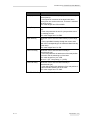
Trigger Settings
This option specifies how the product is detected and depends upon
whether the products are moving past the laser on a conveyor or are
placed as stationary objects manually. The availability of the individual
trigger settings depends on the selected trigger type and the product
movement.
Figure 5-11: Trigger Settings
Rev AC
Line Setup
5-19
CLARiTY Laser Controller System Manual
The trigger settings page allows the user to set the following parameters:
Parameter
Description
Start Delay
Start Delay defines the distance until the marking process is started, which is
the distance between the center of the marking field of the laser system and the
center of the marking on the product. After the trigger the product has to cover
this distance before is in front of the marking head. If No Product Movement is
selected, then the start delay defines the time between start trigger pulse and
marking in milliseconds (ms).
Blocking
Blocking defines the distance the product has to cover before the next marking
can be started. If No Product Movement is selected, then the blocking defines
the time that the product has to pass after a start trigger until a next
trigger is accepted.
Table 5-6: Trigger Settings Page parameters
5-20
Line Setup
Rev AC
CLARiTY Laser Controller System Manual
Parameter
Description
Trigger Mode
Allows the user to select one of the following settings to determine the trigger
for the product marking:
External Rising: Select the trigger mode as External Rising if the trigger pulse
is to be given by the product that is entering the product detection zone.
External Falling: Select the trigger mode as External Falling if the trigger pulse
is to be given by the product that is leaving the product detection zone.
Internal Once: If Internal once is selected then marking is started on selecting
the start button.
Internal Continuous: If Internal Continuous is selected then marking is
continuous and can be stopped manually.
Note: The default value is External Rising.
Note: If the line direction is static, then all the four modes are available, else
only External Rising and External Falling modes are available.
Table 5-6: Trigger Settings Page parameters (Continued)
Rev AC
Line Setup
5-21
CLARiTY Laser Controller System Manual
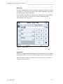
Marking Field
There may be obstacles on the line that obscure part of the laser marking
area. The actual marking area of the laser is restricted to inhibit the laser in
these areas.
If the maximum marking field is not being used (Use Max Marking Field is
set to No), then the user can select each border to the required size. This
option allows the user to increase or decrease any or all of the four borders
of the laser marking area (see Figure 5-12).
Figure 5-12: Marking Field
The border limits are determined by the edge of the marking area nearest
to the border being moved and the current position of the opposite border.
For example, the left border is limited by the left edge of the marking area
and the current right border.
5-22
Line Setup
Rev AC
CLARiTY Laser Controller System Manual
If Use Max Marking Field is set to Yes, the controller uses the maximum set
marking field for marking (see Figure 5-13).
Figure 5-13: Marking Field_Max
Starting the Laser Marking
1 If the laser system has a manual keyswitch, turn to close position
. If the laser system has a software keyswitch, press the
keyswitch button
2
on the home screen.
Enter the password if prompted.
Note: There will be no password prompt if passwords are disabled or if the
user has already logged in.
3 When keyswitch status is enabled/closed, the status bar indicates
STARTING UP and changes to OFFLINE. The stop and start run icons
become active.
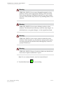
Warning
PERSONAL INJURY. Danger to Eyes and Skin. People within the
area of the laser must wear suitable safety goggles against direct,
reflected or diffusely scattered laser radiation.
Rev AC
Starting the Laser Marking
5-23
CLARiTY Laser Controller System Manual
Warning
PERSONAL INJURY. Never expose flammable materials to laser
radiation. Always ensure appropriate shielding of the laser beam.
Errors during marking on flammable materials (e.g. paper) might
cause fire. Take suitable safety measures by installing smoke or fire
detectors.
Warning
PERSONAL INJURY. Never expose reflecting surfaces to laser
radiation. The reflected laser beam may cause the same dangers - in
individual cases even greater dangers - as the original laser beam.
Warning
PERSONAL INJURY. Never expose unknown materials to laser
radiation. Some materials (e.g. polyethylene, polypropylene, glass)
are easily penetrated by the laser beam, although they seem to be
opaque to human eye.
Warning
PERSONAL INJURY. Danger of explosion. Make sure that the laser
area is free of explosive materials or vapors.
Note: For more safety information, refer Laser System Manual.
4 Touch the Run button
5-24
Starting the Laser Marking
to start marking.
Rev AC
CLARiTY Laser Controller System Manual
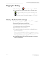
Stopping the Marking
1 Touch the Stop button
. The status bar changes to OFFLINE.
2 To disable the laser system, touch the software keyswitch button
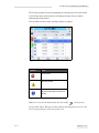
to toggle to disable position or open the manual keyswitch
on the laser system. The status bar changes to SHUTDOWN.
Viewing the Current Job or Image
The name of the current job is displayed on the CLARiTY home page (see
Figure 5-3 on page 5-3). Before starting the production line, make sure that
the current job is the job that you want to mark.
To view more details of the current job, proceed as follows:
1 Touch the name of the job on the home page.
2 This will display a preview of the job.
3 To magnify the image on the screen, double touch on the image to
zoom in and zoom out.
If you are satisfied that the job is displayed correctly, you can start
marking as described in “Print Position” on page 5-4. If the current job
is not the job that you want to mark, refer to the instructions in
“Selecting a Job for Marking” on page 5-3.
4 Touch the Back button on the navigation bar, or the Home button to
return to the home page.
Rev AC
Stopping the Marking
5-25
CLARiTY Laser Controller System Manual
Downloading a Job File
A job file can be downloaded from the PC to the laser system using the
following methods:
• Direct cable connection (serial port of TCP/IP)
• USB memory stick
Download Job File using TCP/IP or Serial Connection
1 Connect the communications cable (serial or ethernet) between the PC
and the corresponding port of the laser system.
Note: The laser system must be turned on to download job files.
2 Click the laser system icon from the tool bar in CLARiSOFT. The Print
window appears (see Figure 5-14 on page 5-26).
3 Ensure that the Real-Time Coder is selected.
4 Ensure that the correct laser system is displayed in the Select Output
Device menu.
5 Select Download under Image Options.
Figure 5-14: Select Output Device
5-26
Downloading a Job File
Rev AC
CLARiTY Laser Controller System Manual
6 To download only the currently opened Job file, select the Current
Image button.
To download multiple Job files that have been saved to the PC, select
the File button and navigate to the location on the PC where the files
are saved. Highlight all of the Jobs you wish to transfer and select
Open.
A preview or list of the selected job(s) appears (see Figure 5-15).
Figure 5-15: Print Preview of Job
7 Click the OK button.
The Progress window which displays the status bar appears. The
status bar indicates the status of the job downloading process
(see Figure 5-16).
Figure 5-16: Progress Window
Ensure the Job now exists in the laser system's database (see
“Selecting a Job for Marking” on page 5-3)
Rev AC
Downloading a Job File
5-27
CLARiTY Laser Controller System Manual
8 Disconnect the communications cable between the PC and the laser
system if no longer needed.
Download a Job File using USB Memory Stick
Do the following tasks to download a job file from the PC to the laser
system using a USB memory stick:
1 Insert the USB memory stick into the PC.
2 On the File menu, click Job Download (see Figure 5-17). The Download
window appears (see Figure 5-18 on page 5-29).
Figure 5-17: Job Download Command
5-28
Downloading a Job File
Rev AC
CLARiTY Laser Controller System Manual
Figure 5-18: Job Download Command
3 Ensure that the Real-Time Coder is selected (see Figure 5-18).
4 Ensure that the correct laser system is displayed in the Select Output
Device menu.
Note: If you do not select the correct output device, the image will not be
correct for the laser system.
5 Select Print to File from Image Options.
6 Select the USB memory device to use from the drop-down menu.
Note: The Print What options will not display until a suitable memory
device is selected.
7 To download only the currently opened Job file, select the Current
Image button.
To download multiple Job files that have been saved to the PC, select
the File button and navigate to the location on the PC where the files
are saved. Highlight all of the Jobs you wish to transfer and select
Open.
Rev AC
Downloading a Job File
5-29
CLARiTY Laser Controller System Manual
8 The confirmation window appears (see Figure 5-19).
Figure 5-19: Confirmation Window
9 Click the OK button to continue.
After the files are downloaded, the message shown in Figure 5-20
appears.
Figure 5-20: Download Complete
Caution
Failure to use the Print to File procedure will result in errors and
rotated images.
10 Remove the USB Memory stick from the PC.
5-30
Downloading a Job File
Rev AC
CLARiTY Laser Controller System Manual
Deleting a Job from the Jobs Database
To remove jobs that are no longer required, proceed as follows:
1 Touch the Tools icon on the home page.
2 Touch the Database icon on the tools page to open the database page.
3 Select the required database (internal or external) and touch Edit to go
to the deletion screen (see Figure 5-21). This page contains a list of all
the available jobs along with details of the space available for the
storage of new jobs.
Figure 5-21: Database Delete Window
4 Touch the name of the job that you want to remove from the list of
jobs. The job image appears in the preview window. Make sure that
the job is the one that you want to delete.
5 Touch Delete to delete the job.
Rev AC
Deleting a Job from the Jobs Database
5-31
CLARiTY Laser Controller System Manual
6 Confirm the job to be removed (see Figure 5-22).
Figure 5-22: Confirmation Screen
7 Touch Yes to remove the job.
8 Repeat steps 4 to 7 to remove other jobs that are not required.
Note: You can touch Select All to remove all the jobs from the list. The job
preview will not be displayed if more than one job is selected.
9 Touch the Home icon to return to the home page.
Turning Off the Controller
Turn OFF the controller mains power switch.
To power off the laser system, follow the instructions in the Laser System
Manual.
5-32
Turning Off the Controller
Rev AC
Additional Controller
Operations
6
This chapter contains the following topics:
• Availability
• Availability fault table
• User editable fields
• Touch to edit
• Production audit log
• How to update controller software
• How to set the screen orientation
• How to create a job
• CLARiTY power saving
Availability
Introduction
Availability is a measurement of equipment uptime. It is the amount of
time that the equipment is ready to run when required by production.
This is one of the three key metrics of OEE.
The ‘Availability’ tool helps to isolate operational versus laser system
issues and allows the user to track the laser system downtime and view
the downtime statistics. The pareto of faults that allows the analysis of
runtime measurement data helps the user to understand and eliminate the
more frequent causes of both laser system and operational downtime.
The availability shows two basic availability metrics simultaneously:
• Laser system Availability
• Operational Availability
Rev AC
Availability
6-1
CLARiTY Laser Controller System Manual
Note: Operational Availability can be changed between two separate production
time proxies as required by the user: "power on" and "running" mode. For more
information, refer “Operational Availability” on page 6-3.
Operating Time
Availability% =
Planned Production Time
Where
• Operating Time is Total Laser system Uptime
• Planned Production Time is the Actual Line Run Time Expected*.
*
Based on proxy selected 'power on' or 'running'.
Laser System Availability
Laser System Availability tracks the downtime directly related to an
internal error (fault) such as
• Power supply: Overtemperature Fault
• Beam Shutter Fault
• Filter Full Fault
Laser System Availability is defined as
Laser System Downtime
Laser System Availability = 1 Laser System Total Time
‘Laser System Total Time’ is the total amount of time for which the laser
system is turned on (has power applied). If the laser system is powered
down when a fault is active, the amount of time that the laser system is off
is also included in this laser system total time.
Laser System Total Time = ('Power On' time) + ('Power Off' time in
fault state)
6-2
Availability
Rev AC
CLARiTY Laser Controller System Manual
‘Laser System Downtime’ is the amount of ‘Laser System Total Time’ the
laser system has spent in a ‘Laser System Fault State’. ‘Laser System Fault
State’ is defined as the period where the Laser System is not available due
to a fault identified as a laser system fault.
Laser System Downtime = Laser System Total time in a fault state
Operational Availability
This is a broader measure to reflect the full impact of the down time to
production line. Operational Availability tracks the downtime related to
faults that might be classed as “Procedural” such as:
• No encoder connected
• No template list selected
• The marking head is not connected
The impact may be due to laser system issues, operator related issues, shift
changeovers and so on.
Operational Availability is defined as
Operation Downtime
Operational Availability = 1 Production Time
The Production Time Proxy allows the availability calculation to change
between customer selected operating modes, running or laser system-on.
The production time is defined based on the production time proxy
chosen:
• Running: If both laser system and laser are switched ON.
• Power On: If the laser system is switched ON irrespective of the status
of the laser.
If the laser system is powered down when a fault is active, the amount of
time that the laser system is off is also included in the production time.
Production Time Running = (Running time) + ('Power Off' time in
fault state)
Where,
Rev AC
Availability
6-3
CLARiTY Laser Controller System Manual
Running time is the time when Laser is ON or requested to be turned ON.
Production Time Power ON = (Power 'ON' time) + ('Power Off' time in
fault state)
Where,
Power ‘ON’ time is the time for which the laser system is switched ON
irrespective of the status of the laser.
‘Operation Downtime’ is the amount of ‘Production Time’ the laser
system has spent in an ‘Operation Fault State’. ‘Operational Fault state’ is
defined as the period where the laser system is not available due to a fault
identified as a operational fault.
Operation Downtime = Total time in a fault state
Operation Downtime
When the laser system enters a laser system fault state (as indicated in
Table 6-5 on page 6-16), the downtime counter starts. The laser system
remains in this operation fault state until the fault is cleared. The operation
to clear the fault is indicated in the Table 6-5 on page 6-16. If the laser
system is powered down in a operation fault state, the downtime counter
continues until laser system is powered on and the fault is cleared.
6-4
Availability
Rev AC
CLARiTY Laser Controller System Manual
Availability Page
Touch Performance on the Home page.
Performance
Figure 6-1: Home page
Displays the Performance Page. Touch Availability to access the availability
page.
Availability
Figure 6-2: Performance
Rev AC
Availability
6-5
CLARiTY Laser Controller System Manual
Displays the Availability page (see Figure 6-3). The user can view
simultaneously the laser system availability and operational availability
data against the time frame. The history of the availability data in the
Timeframe column enables the user to correlate seasonal changes affecting
availability.
Figure 6-3: Availability
Note: Arrows shown in the availability cells indicates the presence of data for
drilling down. Select the cell to view the specific data for detailed analysis.
Option
Description
Timeframe
Allows the user to view laser system and
operational availability values for different
available time frames. The history of the
availability data enables the user to correlate
seasonal changes affecting availability.
Laser System
Availability
Shows the laser system availability data.
Operational
Availability
Shows the operational availability data based on
the proxy in use for the calculation, that is
"Power On" time or "Running" time
Table 6-1: Availability Page options
6-6
Availability
Rev AC
CLARiTY Laser Controller System Manual
Option
Description
Production Time
Proxy
Allows laser system availability calculation to
change between user selected operating modes
that is either ‘running’ or ‘laser system-on’
mode.Proxy choice ensures the calculation of
availability matches the operating mode of user.
The operational availability column in the Availability page (see Figure 6-3) shows the proxy
selected by the user.
Export to USB
Allows the user to export the event log to USB
stick. The UI will take the user through the steps
required to download to USB.
Shows that further information is available.
Touch the cell to view the Fault Pareto page for
the selected availability data. The page displays
the fault type, downtime and fault frequency
(see Figure 6-4)
Table 6-1: Availability Page options (Continued)
Figure 6-4: Fault Pareto for Operational Availability
Option
Description
Fault type
Description of the error code and fault. Touch
the fault type to view the detailed description
of the fault and possible solutions.
Downtime
The total duration of time the laser system
was in this fault state.
Table 6-2: Fault Pareto
Rev AC
Availability
6-7
CLARiTY Laser Controller System Manual
Option
Description
Frequency
The number of times the laser system had
this fault in the time frame.
Sort By
Allows the user to sort the list based on laser
system downtime or fault frequency.
Change
Timeframe
Allows the user to view fault pareto page for
different available time frames.
Table 6-2: Fault Pareto (Continued)
6-8
Availability
Rev AC
CLARiTY Laser Controller System Manual
Option
Description
Laser system/
Operational
Availability
Allows the user to toggle between laser
system and operational availability fault
pareto page.
Table 6-2: Fault Pareto (Continued)
Touch
to view the Event page (see Figure 6-5). Event page displays the date,
time and duration of each occurrence of that specific fault. This page can be used
to correlate the occurrence of a fault with other events in the production facility.
Figure 6-5: Event
Rev AC
Availability
6-9
CLARiTY Laser Controller System Manual
Touch
to view the Parameter page (see Figure 6-6). Parameter page displays
the detailed laser system health parameters logged when the specific fault
occurred.
Figure 6-6: Parameter
Event Time
It is the time when the fault occurred.
Data is shown for 1 minute and 5 minutes prior to the event to illustrate data
trends.
The laser system highlights the parameters which are out of range. Combining this
information to all noted symptoms can expedite root cause analysis.
Touch Go to Event Log to view Event log page (see Figure 6-7 on page 6-11).
You can also view this page by navigating through Tools > Diagnostics >
Printhead.
6-10
Availability
Rev AC
CLARiTY Laser Controller System Manual
The Event log retains all activities happening for 180 days period. It can be useful
to check other laser system activities occurring at the same time as a fault to
understand the fault context.
You can filter to remove status, warnings, alarms as required.
Figure 6-7: Event log
Symbol
Type
Alarm event.
Warning events.
Status- a laser system event
where no warnings or alarms are
raised.
Table 6-3: Event Log symbols
Note: If an event has caused downtime then the symbol
will be present
along with the Alarm, Warning or Status symbols indicating that you can view the
laser system parameters at the time of that event.
Rev AC
Availability
6-11
CLARiTY Laser Controller System Manual
Option
Description
Hide Alarms
Allows the user to Show/Hide any alarm
events from the event log list.
Hide
Warnings
Allows the user to Show/Hide any warning
events from the event log list.
Hide Status
Allows the user to Show/Hide any status
events from the event log list.
Export to
USB
Allows the user to export the event log and
associated parameter snapshots to USB
stick. The UI will take the user through the
steps required to download to USB.
Table 6-4: Event Log Page Option
Touch on the event message for detailed description of the fault or warning event.
The user interface displays a detailed description, likely cause and resolution.
Figure 6-8: Event log diagnostics
This data can be exported to USB for further interrogation.
See “Export to USB” on page 6-13 section for information on how to export to
USB stick.
6-12
Availability
Rev AC
CLARiTY Laser Controller System Manual
Export to USB
The following information can be exported to an external USB stick in a
.csv format:
• Availability Metrics
• Event Log
Do the following tasks to export the data to the USB stick:
1 Insert USB stick to the external USB connector.
Note: ‘Export To USB’ button is activated only when a USB stick is
inserted.
Note: Ensure that the USB stick does not have any previous exported data as
you will be asked to overwrite the files (see Figure 6-9).
Figure 6-9: Overwrite Files
2 Export to USB.
Rev AC
Availability
6-13
CLARiTY Laser Controller System Manual
To export Availability Metrics
a. From Home page, navigate to Performance > Availability (see
Figure 6-3 on page 6-6).
b. Select Export to USB.
c. Confirmation page will be displayed (see Figure 6-10).
Figure 6-10: Export Availability Metrics Confirmation
d. Select OK.
e. On completion, success page will be displayed.
Figure 6-11: Export Success
f. Select OK and remove the USB stick.
6-14
Availability
Rev AC
CLARiTY Laser Controller System Manual
To export Event Log
a. Navigate to Tools > Diagnostics > Printhead > Event Log (see
Figure 6-7 on page 6-11).
b. Select Export to USB.
c. Confirmation page will be displayed (see Figure 6-12).
Figure 6-12: Export Event Log Confirmation
d. Select OK.
e. On completion, success page will be displayed.
Figure 6-13: Export Success
f. Select OK and remove the USB stick.
Rev AC
Availability
6-15
CLARiTY Laser Controller System Manual
3 The files can be exported into Microsoft EXCEL, or other spreadsheet
tools and can be used to create graphs and logs for use in monitoring
the laser performance (see Figure 6-14).
Figure 6-14: Exported Data in Microsoft EXCEL
Availability Fault Table
This table lists the faults that affect laser and operational downtime. For
detail information on Error and how to clear the error, refer Table 8-4 on
page 8-6.
Fault
Code
Description of Fault
Laser System Downtime (faults impacting
the laser availability)
Operational Downtime
(faults impacting the
operational availability)
E00100
Critical error SP
Yes
Yes
E00101
Stack error SP
Yes
Yes
E00102
SP received unknown
command from AOS
Yes
Yes
E00103
Timing error SP
Yes
Yes
E00104
AOS data transfer delayed
Yes
Yes
E00105
Marking aborted, product
movement too fast
No
Yes
E00200
Laser not ready
Yes
Yes
E00201
Laser supply: voltage too high
or too low
Yes
Yes
E00202
Laser overtemperature
Yes
Yes
E00203
Unknown laser beam source
Yes
Yes
E00204
General error
Yes
Yes
Table 6-5: Fault Table
6-16
Availability Fault Table
Rev AC
CLARiTY Laser Controller System Manual
Fault
Code
Description of Fault
Laser System Downtime (faults impacting
the laser availability)
Operational Downtime
(faults impacting the
operational availability)
E00205
Internal cooling circuit: Flow
too low
No
Yes
E00206
RF circuit: VSWR fault
Yes
Yes
E00207
RF circuit: Overmodulation
Yes
Yes
E00208
RF circuit: Incorrect RF PSU
power
Yes
Yes
E00209
Back reflection
Yes
Yes
E00210
Red laser emission LED
defective - Hardware error
Yes
Yes
E00211
Defective element in laser
supply circuit
Yes
Yes
E00212
Wrong LIC detected
Yes
Yes
E00213
Wrong HIC detected
Yes
Yes
E09000
Marking head: Temperature
of FM/MHI assembly group
too high
No
Yes
E09001
Marking head: Supply voltage
too low
Yes
Yes
E09002
Marking head:
Overpositioning of X mirror
Yes
Yes
E09003
Marking head:
Overpositioning of Y mirror
Yes
Yes
E09004
Marking head: Overcurrent X
mirror
Yes
Yes
E09005
Marking head: Overcurrent Y
mirror
Yes
Yes
E09006
Marking head: No X mirror
connected
Yes
Yes
E09007
Marking head: No Y mirror
connected
Yes
Yes
E09012
Communication error ACC ->
FM/MHI: Gaps in the data
flow
Yes
Yes
E09021
Internal error: Cannot set
control mode of the FM/MHI
Yes
Yes
Table 6-5: Fault Table (Continued)
Rev AC
Availability Fault Table
6-17
CLARiTY Laser Controller System Manual
Fault
Code
Description of Fault
Laser System Downtime (faults impacting
the laser availability)
Operational Downtime
(faults impacting the
operational availability)
E09022
Internal error: Cannot set
configuration mode of the FM/
MHI
Yes
Yes
E09023
Internal error: Cannot set
download mode of the FM/
MHI
Yes
Yes
E09100
No communication with marking head
Yes
Yes
E09101
Internal error: Error status of
the FM/MHI cannot be reset
Yes
Yes
E09102
Interrupted communication
with marking head
Yes
Yes
E09103
Internal error: FM/MHI not in
configuration mode, cannot
executed command
Yes
Yes
E09104
No data received from the
marking head
Yes
Yes
E10001
No data can be read from the
system database
Yes
Yes
E10002
Backup of system database
was loaded!
Yes
Yes
E10003
Cannot write (all) to the
backup of the system database
No
Yes
E10004
Cannot write to system database
Yes
Yes
E10005
Cannot read backup of the
system database
Yes
Yes
E10006
Overflow of system database
No
Yes
E10007
QMark update failed. Please
try the update again
Yes
Yes
E10008
A change requires rebooting
the laser
Yes
Yes
E10101
Version conflict (command
not executed)
Yes
Yes
E10102
Unknown command
Yes
Yes
Table 6-5: Fault Table (Continued)
6-18
Availability Fault Table
Rev AC
CLARiTY Laser Controller System Manual
Fault
Code
Description of Fault
Laser System Downtime (faults impacting
the laser availability)
Operational Downtime
(faults impacting the
operational availability)
E10103
Key not found in system
database
Yes
Yes
E10104
Database write error
Yes
Yes
E10105
Database read error
Yes
Yes
E10106
Template contains no data
No
Yes
E10107
Template does not exist
No
Yes
E10108
No variables in template
No
Yes
E10109
Format is invalid
No
Yes
E10111
Errors while saving
Yes
Yes
E10113
This database entry cannot
be deleted since other entries
depend on it
No
Yes
E10114
The transmitted object cannot
be saved to the database.
Please check whether your
system supports the object
No
Yes
E10115
Too many variables are used
in the templates. Please
delete all templates you do
not need
No
Yes
E10116
Error while reading directory
Yes
Yes
E10300
Data for initialization cannot
be read completely from the
database
Yes
Yes
E10302
Shutter does not stay open
Yes
Yes
E10303
Shutter does not stay closed
Yes
Yes
E10401
Template invalid
Yes
Yes
E10404
External text: Value can be
marked only once
No
Yes
E10407
The beam shutter does not
open
Yes
Yes
E10408
The beam shutter does not
close
Yes
Yes
E10409
System error during
preparation of marking
Yes
Yes
Table 6-5: Fault Table (Continued)
Rev AC
Availability Fault Table
6-19
CLARiTY Laser Controller System Manual
Fault
Code
Description of Fault
Laser System Downtime (faults impacting
the laser availability)
Operational Downtime
(faults impacting the
operational availability)
E10500
Cannot load database
Yes
Yes
E10501
Backup database has been
loaded
Yes
Yes
E10507
Error while reading the
objective file
Yes
Yes
E10508
Error while reading the laser
file
Yes
Yes
E10509
Error while reading the head
file
Yes
Yes
E10510
No FPGA image file
available!
Yes
Yes
E10511
No SP program available!
Yes
Yes
E10512
AllprintBasic: Protocol
configuration error
No
Yes
E10513
AllprintBasic: Configuration
error of the serial interface
No
Yes
E10514
FM/MHI download error
Yes
Yes
E10515
FM/MHI download: File is
missing
Yes
Yes
E10516
The marking head is not
connected
Yes
Yes
E10518
The parameter set does not
correspond to the laser type.
Please replace this entry in
the database
No
Yes
E10519
Please select a lens
corresponding to the marking
head
Yes
Yes
E10520
A marking head has been
identified which is not
admitted for this laser type
No
Yes
E10550
AllprintBasic: Syntax error
No
Yes
E10551
The template does not
contain the requested
variable
No
Yes
E10553
Illegal command in
AllprintBasic command string
No
Yes
Table 6-5: Fault Table (Continued)
6-20
Availability Fault Table
Rev AC
CLARiTY Laser Controller System Manual
Fault
Code
Description of Fault
Laser System Downtime (faults impacting
the laser availability)
Operational Downtime
(faults impacting the
operational availability)
E10554
The AllprintBasic command
"Error" has been executed
No
Yes
E10601
No template list selected
No
Yes
E10602
The chosen template number
cannot be assigned to any
template
No
Yes
E10701
Out of memory. Cannot
create database object
Yes
Yes
E10702
Format error while creating a
database object
Yes
Yes
E10800
DSP does not send
telegrams
Yes
Yes
E10811
DSP buffer overflow
Yes
Yes
E10813
No encoder connected
No
Yes
E10814
No trigger detector connected
No
Yes
E10900
General CAN bus error
No
Yes
E10901
A CAN node has carried out
an inadmissible reset
Yes
Yes
E10902
Lost connection to a CAN
node
Yes
Yes
E10903
A CAN node cannot be
initialized
Yes
Yes
E10906
The customer interface (CI)
indicates an error of the
external exhaust
No
Yes
E10907
The customer interface (CI)
indicates an external error
No
Yes
E10909
A CAN node has carried out
an inadmissible state change
Yes
Yes
E10913
File is missing
No
Yes
E10914
Faulty transmission to a node
No
Yes
E10915
A CAN node does not react
after download or software
reset
Yes
Yes
E10916
Faulty download to node
Yes
Yes
Table 6-5: Fault Table (Continued)
Rev AC
Availability Fault Table
6-21
CLARiTY Laser Controller System Manual
Fault
Code
Description of Fault
Laser System Downtime (faults impacting
the laser availability)
Operational Downtime
(faults impacting the
operational availability)
E10917
A CAN node signals unsuitable software
Yes
Yes
E10918
A problem with the RF driver
file occurred
Yes
Yes
E10919
A driver error prevents
triggers being transmitted
from the CAN bus
Yes
Yes
E10920
A driver error prevents control
of the red emission LED
Yes
Yes
E10921
Less than two CI input bus
terminals connected
Yes
Yes
E10922
Less than two CI output bus
terminals connected
Yes
Yes
E10923
Ext. template selection
requires at least 4 CI input
bus terminals
No
Yes
E10926
Entry is missing in the
database
Yes
Yes
E10929
CAN bus error
Yes
Yes
E19201
Template does not exist
No
Yes
E19202
Faulty template
Yes
Yes
E19203
Parameter set does not exist
Yes
Yes
E19204
Product registration does not
exist
Yes
Yes
E19205
At least one index level does
not exist in the parameter set
Yes
Yes
E19210
The direct marking cannot be
carried out
No
Yes
E19301
The template sequence does
not contain any template
No
Yes
E19302
The template in the template
sequence does not exist
No
Yes
E19303
The heads of templates of a
template sequence must be
identical
No
Yes
Table 6-5: Fault Table (Continued)
6-22
Availability Fault Table
Rev AC
CLARiTY Laser Controller System Manual
Fault
Code
Description of Fault
Laser System Downtime (faults impacting
the laser availability)
Operational Downtime
(faults impacting the
operational availability)
E19304
The product registrations of
templates of a template
sequence must be identical
No
Yes
E19305
Product registration does not
exist
No
Yes
E19306
Defective template in the
template sequence
Yes
Yes
E19307
The circuit for external laser
enable has been opened
No
Yes
E19308
Cannot select beam source
Yes
Yes
E19309
The clock had to be restarted.
Please set the time!
Yes
Yes
E19311
Fiber Laser Extension Board
has not been detected
Yes
Yes
E19312
Fiber Laser Overtemperature
Yes
Yes
E19313
The laser stop switch has
been pressed
No
Yes
E19314
SL501 Laser Extension Board
cannot be identified
Yes
Yes
E19413
The interlock circuit has been
opened
No
Yes
E19502
Suction control error
Yes
Yes
E19504
The filter is full
No
Yes
E19509
Safety connector has a signal
on unused line
No
Yes
E26100
LHC has unexpected internal
errors
Yes
Yes
E29009
Beam shutter error
Yes
Yes
E33301
Power supply: Inadmissible
terminal voltage
Yes
Yes
E34200
Power supply:
Overtemperature
Yes
Yes
E34201
Internal cooling circuit:
Temperature above/below
limit value
Yes
Yes
E34203
RF driver: Temperature error
Yes
Yes
Table 6-5: Fault Table (Continued)
Rev AC
Availability Fault Table
6-23
CLARiTY Laser Controller System Manual
Fault
Code
Description of Fault
Laser System Downtime (faults impacting
the laser availability)
Operational Downtime
(faults impacting the
operational availability)
E39009
RF driver: VSWR error
Yes
Yes
E39012
Power supply: General error
Yes
Yes
Table 6-5: Fault Table (Continued)
User Editable Fields
Some jobs contain user editable fields. These fields are part of the job that
can be changed. There are three types of user editable fields:
• Variable TEXT fields.
For example, they are used for batch codes, product names, and other
text jobs.
• Variable DATE fields.
For example, they are used for sell by dates.
• Variable COUNTER fields.
Allows you to modify the starting value for a counter.
If the selected job has a user editable field, the interface prompts the user
to review this field and edit if required.
Note: Each field has a check box. The check box is unchecked initially. As you
enter the data and touch OK, the user interface automatically checks the box. You
can proceed to the next step only when all the boxes are checked.
How to Change the Text and Date Fields
To edit the user field, proceed as follows:
1 When a job is selected, the list of user editable fields in the job are
displayed.
6-24
User Editable Fields
Rev AC
CLARiTY Laser Controller System Manual
2 Touch the required field from the list to select it (the first one in the list
is automatically selected). The default data for that field appears in the
preview window (Figure 6-15).
Figure 6-15: Default Data Window
3 If the information in the preview window is the information that you
want to print, go to step 5. If you want to change the information,
perform step 4.
4 Touch Edit to modify the information.
For text fields, do the following tasks:
a. Use the alpha key pad to enter the data.
The CLARiTY Operating system supports a number of standard
languages for use with 'User Entered' text information.
Rev AC
User Editable Fields
6-25
CLARiTY Laser Controller System Manual
b. Touch the 'Language Selection Key', to access the available
language selections (see Figure 6-16).
Language Selection Key
Figure 6-16: Default Keypad
c. The keypad functions the same way as the keypad on a computer.
Make necessary changes to the information.
6-26
User Editable Fields
Rev AC
CLARiTY Laser Controller System Manual
For date fields, do the following tasks:
d. Touch the data window to display the Calendar page
(see Figure 6-17).
Figure 6-17: Calendar Page
e. Touch the + or - button to change the month and year.
f. Touch the date on the calendar to choose the date of the month, and
touch OK.
Note: Any dates that are not available for selection because of pre-defined
rules that may have been set in CLARiSOFT are dimmed.
5 Touch OK when you are satisfied that the information in the data
window is correct. The user interface checks the check box. If there are
only two user editable fields in the job, the user interface
automatically displays the second field. If there are three or more
fields, it displays the list of user editable fields, so that you can select
one.
When you touch OK at the final field for this job (and all the check
boxes are checked) the user interface shows you the preview of the
image.
6 At the preview, perform one of the following:
• If you are satisfied with the image and you want to run the new job,
touch OK. Products will be printed with the new image until you
make further changes or select a new job.
• If you are not ready to print the job, you can leave this screen as it
is. You can touch OK at a later stage, to select the job at that time.
Rev AC
User Editable Fields
6-27
CLARiTY Laser Controller System Manual
• If you want to step back through the job select screens to make
alterations to the variable data, touch Cancel.
• To cancel the job selection altogether, touch Home
button.
Touch To Edit
To update and change user fields quickly and easily in a printing job, the
user can use the ‘Touch To Edit’ feature.
Note: Touch to Edit feature is turned off by default and needs to be activated in
Clarity Configuration Manager.
1 Select the ‘Current Job Details Bar’ to display the job preview.
Figure 6-18: Message preview- Touch to edit
2 Touch the
6-28
Touch To Edit
button.
Rev AC
CLARiTY Laser Controller System Manual
3 The job opens, with the user editable fields highlighted.
Note: Only jobs that have user editable fields can be edited using Touch to
Edit feature. These are set up in CLARiSOFT during message creation.
Figure 6-19: User Editable Fields Highlighted
4 To edit a user field, touch the user field.
5 The appropriate user field editor, based on the user field type, is
displayed for the update.Update the user field as required and touch
OK.
Figure 6-20: User Field Editor
Rev AC
Touch To Edit
6-29
CLARiTY Laser Controller System Manual
6 If there are additional user fields, repeat step 4 and step 5 for each
field.
7 Touch OK after editing all the required user fields. The job will be
updated in the printer and displayed in the ‘current job details bar’
following the next print.
Production Audit Log
The production audit log shows the log of machine changes and user
changes made.
Note: Production Audit Log is turned off by default and needs to be activated in
Clarity Configuration Manager. The logging mode can be set to “None”,
“Normal” or “Advanced”.
In Normal logging mode, the log entries are deleted if there are over 500
log entries and older than 90 days.
In Advanced logging mode, entries must be archived to a USB stick before
logs will be deleted.
Figure 6-21 shows the audit log for both machine events and user events.
The user can also filter results to show either user events only or machine
events only (see Table 6-6).
Figure 6-21: Production Audit Log
6-30
Production Audit Log
Rev AC
CLARiTY Laser Controller System Manual
Button
Function
Lists both machine and
user events
Lists only user events
Lists only machine events
Table 6-6: Buttons to Filter the Log
The following machine events are logged.
• CLARiTY Started – [software version, PCB serial number]
• CLARiTY Exit
• Power Failure detected
• Fault/Warning raised – [Fault Name]
• Fault/Warning cleared – [Fault Name]
• Parameters download (CCFG)
The following user events are logged. Each user event is also labelled with
name of the user performing the change when advanced passwords are
turned on.
• Parameter change – [Param Name, old and new value]
• CLARITY Clone restored - [File name]
• CLARITY Archive restored - [File name]
• CLARiTY Update started – [update name]
Rev AC
Production Audit Log
6-31
CLARiTY Laser Controller System Manual
Touch on any event log to view the details of the log (see Figure 6-22).
Figure 6-22: Parameter Change
How to Update Controller Software
You can update the controller software by following methods:
• USB key
• CLARiTY Configuration Manager
Updating by USB Key
1 Copy the CAB file into the clarityupdate folder on the root of a USB
drive.
2 Plug the USB drive into the coder.
3 Follow the on-screen instructions.
Note: If the instructions does not appear automatically after 15 seconds, navigate
to Tools > Setup > Control > CLARiTYupdate and select the desired software
update.
6-32
How to Update Controller Software
Rev AC
CLARiTY Laser Controller System Manual
Updating by CLARiTY Configuration Manager
1 Start the CLARiTY Configuration Utility. Connect it to the controller.
Note: Ensure that the CLARiTY Configuration Utility has a valid
connection to the printer. This can be observed by the printer icon turning
green and the Active Connection message being displayed in the status pane.
2 Right click on the name of the coder to be updated and select
CLARiTYupdate option.
3 Locate the file with the same name as the part number above.
CLARiTY update starts automatically.
4 On completion, navigate to Tools > Diagnostics > Control > Versions and
ensure that all of the software versions match with those listed below.
Note: Use of a serial link for the CLARiTY update is not recommended due
to the size of update and the resulting transmission time.
How to Set the Screen Orientation
Depending on the position in which the CLARiTY controller is mounted,
it may be necessary to rotate the screen image by 180 degrees.
To change the screen orientation, proceed as follows:
1 Navigate to Tools > Setup > Control. Control page appears (see
Figure 6-23).
Figure 6-23: Control Page
Rev AC
How to Set the Screen Orientation
6-33
CLARiTY Laser Controller System Manual
2 Touch Set Screen Orientation from the list. Set Screen Orientation page
appears (see Figure 6-24).
Figure 6-24: Set Screen Orientation
3 Select 0 or 180 degrees depending on your requirement and select OK.
The screen orientation changes.
Touch the Home icon to return to the home page.
How to Create a Job
Note: Jobs are created offline on a PC using CLARiSOFT software, and are then
downloaded to the printer. For more information, refer to CLARiSOFT manual.
Jobs can be converted from Laser XML format to CIFF format using the
CIFF convertor tool. Refer to CIFF convertor instructions (P/N: 462487).
6-34
How to Create a Job
Rev AC
CLARiTY Laser Controller System Manual
CLARiTY Power Saving
This section describes the behavior of the controller in the various power
saving states. It is possible to set the power saving mode of the controller.
There are four modes:
• None
• Minimal
• High
• Full
The default power saving mode is set to Full.
Figure 6-25: Power Saving Modes
Rev AC
CLARiTY Power Saving
6-35
CLARiTY Laser Controller System Manual
Power Saving Mode = 0: None
User interface will not dim when power is applied.
Power Saving Mode = 1: Minimal
User interface will dim after 1 minute of inactivity.
Activity:
• User touching the screen
• USB keyboard input
• Raising of an warning (e.g. the moment the printer transitions from
No Error into Warning)
• Presence of an error
Power Saving Mode = 2: High
User interface dims after 1 minute of inactivity.
User interface turns off after a further 14 minutes of inactivity.
Activity:
• User touching the screen
• USB keyboard input
• Printing
• Raising of a warning (e.g. the moment the printer transitions from No
Error into Warning)
• Presence of an error
6-36
CLARiTY Power Saving
Rev AC
CLARiTY Laser Controller System Manual
Power Saving Mode = 3: Full
• User interface dims after 1 minute of inactivity.
• User interface turns off after a further 14 minutes of inactivity.
Activity:
• User touching the screen
• USB keyboard input
• Raising of a warning (e.g. the moment the printer transitions from No
Error into Warning)
• Presence of an error
Note: When an error is present the screen will be at full brightness.
Note: When a warning occurs the printer treats it as an activity event and will
dim and switch off after 15 minutes, if the warning is ignored.
Note: In High power saving mode, printing is treated as an activity event.
Rev AC
CLARiTY Power Saving
6-37
Maintenance
7
This chapter contains the following topics:
• Replacement instructions
• Information on care
• Maintaining the power supply
• Maintaining the controller and laser system
Warning
PERSONAL INJURY. Before attempting any maintenance or repair
on laser system and its environment, the laser system must be
disconnected from the power supply.
Replacement Instructions
When you order a spare part kit, the replacement instructions of the
respective spare part are provided along with the kit. For more
information, contact Videojet Technologies Inc. Refer to Chapter ,
“Support and Training” for the contact information.
The replacement instructions are available for the parts included in the
following table.
Spare Part
Liquid Crystal Display (LCD) (Touch Screen)
Printed Circuit Board (PCB)
Controller Spares
Main Switch Assembly
Power Supply Unit
Table 7-1: Available Instructions
Rev AC
Replacement Instructions
7-1
CLARiTY Laser Controller System Manual
Information on Care
• If the display is soiled, it can be cleaned using a commercially
available screen cleaning wipe.
• Ensure any moisture is removed immediately to avoid staining or
damage to the touch screen.
Maintaining the Power Supply
This section contains the information on how to replace the fuse.
Replacing the Mains Fuse
The fuses are the only user-serviceable parts in the power supply unit.
To replace the mains fuse, proceed as follows:
1 Carefully remove the fuse holder (see Figure 7-1).
Fuse Holder
Figure 7-1: Fuse Holder removal
2 Replace the 5 A fuse if it is defective.
3 Refit the fuse holder in its original position.
7-2
Information on Care
Rev AC
CLARiTY Laser Controller System Manual
Maintaining the Controller
Inspection Check point
Frequency
Measures
Check if the touch screen is
clean
As Required
Clean the touch screen by wiping with a dry
soft cloth or cotton pad.
Check if the surface is
clean
As Required
Clean the surface by wiping with a dry soft
cloth or cotton pad.
Controller
Table 7-2: Laser System Maintenance Schedule
Note: Refer to laser manuals for information on maintenance of lasers.
For information on maintenance of the laser system, refer to Laser System
Manual.
Rev AC
Maintaining the Controller
7-3
Troubleshooting
8
This chapter contains the following topics:
• Fault messages and warnings
• Controller fault
• Marking faults
• Additional faults
• CLARiTY error messages and warnings
• Diagnostics
Fault Messages and Warnings
If the user interface displays a fault or warning, perform the following:
• Read the fault or warning message.
• Perform the task as per the message.
• Clear the message from the display (sometimes the message clears
automatically when the fault is corrected, and sometimes you have to
clear it by touching the Clear button).
Rev AC
Fault Messages and Warnings
8-1
CLARiTY Laser Controller System Manual
Reading a Fault Message or Warning
When a fault or warning occurs, CLARiTY displays the fault message in
the status window at the top of all pages.
When a fault occurs, the laser system’s fault output relay will open. If this
relay is wired into the packaging machine’s stop circuit, it can be used to
ensure that the packaging machine is stopped in the event of an error. This
prevents the uncoded product from being produced when the laser
system has a fault.
Figure 8-1: Fault Display
Several faults and warnings may occur at the same time. Faults will
always be displayed first.
To view the faults/warnings in more detail and to view instructions on
what to do about them, touch the red or yellow area in the status window
at the top of the CLARiTY display.
8-2
Fault Messages and Warnings
Rev AC
CLARiTY Laser Controller System Manual
Clearing a Fault Message or Warning
The instructions in this section provides information on how to clear a
fault message. A similar procedure is used to clear warnings.
To view the details of the fault list, proceed as follows:
1 Touch the red FAULT message on the status bar to view the list of
faults (see Figure 8-2).
Figure 8-2: Fault Selection
2 Touch the fault name in the list.
3 The details of the fault is displayed. Follow the on screen instruction
for correcting the fault.
Figure 8-3: Fault Details Display
4 When you have corrected the fault, the Clear button is activated. Press
Clear to remove the fault message.
Rev AC
Fault Messages and Warnings
8-3
CLARiTY Laser Controller System Manual
Controller Fault
Fault
Cause
Solution
CLARiTY
controller is
switched OFF.
Cable not properly connected to
the printer and controller.
Check and correct.
Incorrect cable between the
printer and controller.
Check and correct.
Faulty controller unit.
Check unit and replace the components
as required.
Table 8-1: Controller Fault
Marking Faults
Fault
Cause
Solution
The job is not
marked.
The job is empty, i.e. there are
no markable objects (such as
text, time, date, counter or
barcode fields) in the job.
Open, load and start a job with mark
data in it.
The job was not loaded to the
print memory.
The job must be loaded to the print
memory before marking.
The status of the laser system
is not on ‘Running’.
In order to start marking the START key
has to be pressed.
A shaft encoder is being used
but is not activated in the
system settings.
Activate the shaft encoder in the system
settings.
A shaft encoder is being used
but it is activated in the system
settings of the shaft encoder.
Deactivate the shaft encoder in the
system settings and set the constant
marking speed.
Changes made
to the job are not
marked.
The changes were not loaded to
the print memory.
Reselect the job using the menu from
the Home screen.
The job
orientation is
incorrect
The orientation setting has been
incorrectly set.
Check the Job Orientation settings and
correct.
The mark
position is
incorrect
Laser Position setting is
incorrect.
Check the Laser Position setting and
correct.
Table 8-2: Marking Faults
8-4
Controller Fault
Rev AC
CLARiTY Laser Controller System Manual
Note: For information on laser system faults, refer Laser System Manual.
Additional Faults
Fault
Cause
Solution
The job cannot
be opened.
The job is not compatible with
this Firmware version.
The job must be newly created for this
Firmware version.
After a certain
number of marks
the user interface
automatically
switches to
OFFLINE.
A counter field is marked in
which the counter end value is
predefined and the user
interface switches to OFFLINE
mode when this value is
reached.
Change the specifications for the job.
A limited mark run has been
specified in the job settings
Change the specifications for the job.
Invalid Line
The line selection inputs have
requested a line that is not
configured.
1. Use CLARiTY Configuration Manager
to check that the correct number of lines
have been setup for this system.
2. Check if the line selection inputs are
connected properly.
3. Touch the Clear button to clear this
warning message.
No Line Selected
A mark signal has been
received for a product without
any line selection.
1. Check if the line selection system is
functioning correctly.
2. Touch the Clear button to clear this
fault message.
Printhead Absent
No communication between
laser system and CLARiTY
configuration manager
1. Check cable connections.
2. Restart laser system and controller.
3. Check IP address (Navigate to
Tools > Diagnostics > Control >
Communications > TCP/IP).
If IP address is not at default
192.168.1.1 or as required, navigate to
Tools > Setup > Control >
Communications > IPreset and follow
the instructions to reset the IP address
to default.
Job Download
Failure
Refer to CLARiSOFT manual and
update/correct issues.
Touch the Clear button to clear this fault
message.
Table 8-3: Additional Faults
Rev AC
Additional Faults
8-5
CLARiTY Laser Controller System Manual
CLARiTY Error Messages and Warnings
Error No.
Report on CLARiTY Operator Interface
E1000
‘Job Update Failure’ - The printer was unable to update the current Job
before the next print was required. This usually occurs because products
are too close together. Press the ‘Clear’ button to enable printing to be
restarted.
E1001
‘Count Limit Reached’ - One or more of the counters in the image has
reached the end value set in the image design. Please select a new Job
and press the 'Clear' button to enable printing to be restarted.
E1002
‘Operation Aborted’ - The operation of the printer was intentionally aborted
by a host control system. When ready to do so, the host control system will
clear this abort condition, and then this fault message will automatically
clear and the printer will resume operation.
E1003
‘Realtime Clock Fault’ - There is a problem with the Real time Clock which
is required for the system to operate correctly.
E1004
‘Backup battery is flat’ - The battery which powers the printer's clock is flat.
This means that the date and time, the currently selected Job and some
performance data will be lost when the printer is switched off.
E1005
‘Print Limit Exceeded’ - The current Job was selected with a print limit (i.e. a
limit on the number of times the Job can be printed). This limit has been
reached but the printer has received a further print signal that would have
exceeded the limit.
This error will become clearable after selecting a new job. Alternatively, a
Job selection command or variable data update from an external source will
also make this error clearable.
E1006
‘Image Update Failure’ - CLARiTY was unable to update the image that will
be printed next. This usually occurs because products are too close
together. Press the ‘Clear’ button to enable printing to be restarted.
E1007
‘Image Update Failure’ - CLARiTY was unable to update the image that will
be printed next. This usually occurs because products are too close
together. Press the ‘Clear’ button to enable printing to be restarted.
E1008
‘Power Failure Detected’ - A serious drop in the mains power has been
detected. In order to protect the printer from damage, the high voltage
circuits have been switched off. You must now repower the printer in order
to resume printing. If the problem persists, contact your maintenance
engineer or local service representative.
E1009
‘Corrupt MAC Address’ - The MAC address of this printer is corrupt and the
printer cannot function without a valid MAC address. Contact your
maintenance engineer or local service representative who will be able to
correct this problem.
Table 8-4: Error Messages and Warnings
8-6
CLARiTY Error Messages and Warnings
Rev AC
CLARiTY Laser Controller System Manual
Error No.
Report on CLARiTY Operator Interface
E1010
‘Invalid Line’ - The line selection inputs have requested a line that is not
configured. Use CLARiTY Configuration Manager to check that the correct
number of lines have been setup for this system. Also check that the line
selection inputs are connected properly. Press the ‘Clear’ button below, to
clear this warning message.
E1011
‘Production Disabled’ - A request to print a product has been received for a
line that production has been disabled on. Please press the Job button on
the home screen and check that the line configuration is correct.
Press the ‘Clear’ button below, to clear this fault message.
E1012
‘No Line Selected’ - A print signal has been received for a product without
any line selection. Please check that the line selection system is functioning
correctly. Press the ‘Clear’ button below, to clear this fault message.
E1013
‘BETA Expired’ - The beta period for the release has expired.
Contact your maintenance engineer or local service representative to
correct this problem.
E1014
‘Time and Date may be incorrect’ - The printers time and date may not be
correct. The most common cause for this is that the battery used to backup
the printers clock is flat. If this problem returns the next time the printer is
power on then the battery should be replaced. If the battery is flat the date
and time, the currently selected job and some performance data will be lost
when the printer is switched off.
Press the ‘Clear’ button below, to clear this warning message.
E1100
‘Invalid Job File - bad field reference’ - The Job file is invalid and needs to
be corrected using Clarisoft. There is a circular reference between fields in
the Job file. Use Clarisoft to check and correct the relationships between
fields in this Job file. Then, download the corrected file.
Press the ‘Clear’ button below, to clear this fault message.
E1101
‘Invalid Job File - missing data source field’ - The Job file is invalid and
needs to be corrected using Clarisoft. A field in the Job file refers to another
field for its source of data, but that field is missing from the job file. Use
Clarisoft to ensure that all data source fields used in the Job file are present
and correct in the Job file. Then, download the corrected file.
Press the ‘Clear’ button below, to clear this fault message.
E1102
‘Invalid Job File - duplicate named fields’ - The Job file is invalid and needs
to be corrected using Clarisoft. Duplicate field names were found in the Job
file. Use Clarisoft. to remove or rename fields so that there are no
duplicates. Then, download the corrected file.
Press the ‘Clear’ button below, to clear this fault message.
E1103
‘Invalid Job File - invalid graphic’ - The Job file is invalid and needs to be
corrected using Clarisoft. The Job file refers to a missing or invalid graphic
bitmap file. Use Clarisoft. to check and ensure that all bitmap files, used by
this Job file, display properly in Clarisoft. Then, download the corrected file.
Press the ‘Clear’ button below, to clear this fault message.
Table 8-4: Error Messages and Warnings
Rev AC
CLARiTY Error Messages and Warnings
8-7
CLARiTY Laser Controller System Manual
Error No.
Report on CLARiTY Operator Interface
E1104
‘Invalid Job File - invalid date field’ - The Job file is invalid and needs to be
corrected using Clarisoft.
The Job file you are trying to select contains an incorrectly specified Date
Calculation. The Default Offset for the date falls outside of the date range
specified by the Minimum and Maximum user concession. Use Clarisoft to
correct this error in the Job file. Then, download the corrected file.
Press the ‘Clear’ button below, to clear this fault message.
E1105
‘Invalid Job File - Multiple Transmitted Fields’ - The Job file is invalid and
needs to be corrected using Clarisoft
A Transmitted Field attribute was found on more than one field. Only one
field can be tagged as the transmitted field. Use Clarisoft to correct this
error in the Job file. Then, download the corrected file to Clarity
Press the ‘Clear’ button below, to clear this fault message.
E1200
‘Invalid Job File - invalid barcode character’ - The Job file is invalid and
needs to be corrected using Clarisoft. A barcode in the Job file contains
characters which are not in the character set of the barcode type being
used. Use Clarisoft to check and correct the barcode fields in the Job file.
Then, download the corrected file.
Press the ‘Clear’ button below to clear this fault message.
E1201
‘Invalid Job File - invalid barcode check digit’
The Job file is invalid and needs to be corrected using Clarisoft.
The check digit supplied for a barcode in the Job file is invalid. Use
Clarisoft. to check and correct the barcode fields in the Job file. Then,
download the corrected file.
Press the ‘Clear’ button below, to clear this fault message.
E1202
‘Invalid Job File - EAN barcode out of specification’ - The Job file is invalid
and needs to be corrected using Clarisoft. An EAN barcode in the Job file
contains more than 48 characters, which is the maximum length for this
type of barcode. Use Clarisoft. to check and correct the EAN barcode fields
in the Job file. Then, download the corrected file.
Press the ‘Clear’ button below, to clear this fault message
E1203
‘Invalid Job File - EAN barcode out of specification’ - The Job file is invalid
and needs to be corrected using Clarisoft. The field for an EAN128 barcode
does not contain enough data to form a valid Application Identifier. Use
Clarisoft. to check and correct the EAN128 barcode fields in the Job file.
Then, download the corrected file.
Press the ‘Clear’ button below, to clear this fault message.
E1204
‘Invalid Job File - EAN barcode out of specification’ - The Job file is invalid
and needs to be corrected using Clarisoft. An EAN128 barcode field
contains an application identifier containing non-numeric data, but EAN128
application identifiers must be numeric. Use Clarisoft. to check and correct
the EAN128 barcode fields in the Job file. Then, download the corrected
file.
Press the ‘Clear’ button below, to clear this fault message.
Table 8-4: Error Messages and Warnings
8-8
CLARiTY Error Messages and Warnings
Rev AC
CLARiTY Laser Controller System Manual
Error No.
Report on CLARiTY Operator Interface
E1205
‘Invalid Job File - EAN barcode out of specification’ - The Job file is invalid
and needs to be corrected using Clarisoft. EAN128 barcode fields with an
application identifier of 23 should contain a length digit following the
application identifier. Use Clarisoft. to check and correct the EAN128
barcode fields in the Job file. Then, download the corrected file.
Press the ‘Clear’ button below, to clear this fault message.
E1206
‘Invalid Job File - EAN barcode out of specification’ - The Job file is invalid
and needs to be corrected using Clarisoft. An EAN128 barcode field in the
Job file does not have the number of characters that are specified by its
application identifier. Use Clarisoft. to check and correct the EAN128
barcode fields in the Job file. Then, download the corrected file.
Press the ‘Clear’ button below, to clear this fault message.
E1207
‘Invalid Job File - EAN barcode out of specification’ - The Job file is invalid
and needs to be corrected using Clarisoft. An EAN128 barcode field in the
Job file contains variable length data followed by a separator character;
separator characters should not be used to terminate data in an EAN128
barcode. Use Clarisoft. to check and correct the EAN128 barcode fields in
the Job file. Then, download the corrected file.
Press the ‘Clear’ button below, to clear this fault message.
E1208
‘Invalid Job File - EAN barcode out of specification’ - The Job file is invalid
and needs to be corrected using Clarisoft. An EAN128 barcode field in the
Job file contains data that is out of range (e.g. an hour field set to 25 or a
month field set to 13). Use Clarisoft. to check and correct the EAN128
barcode fields in the Job file. Then, download the corrected file.
Press the ‘Clear’ button below, to clear this fault message.
E1209
‘Invalid Job File - EAN barcode out of specification’ - The Job file is invalid
and needs to be corrected using Clarisoft. An EAN128 barcode field in the
Job file contains an application identifier that requires a digit to specify the
position of the decimal point, but this digit is not present. Use Clarisoft. to
check and correct the EAN128 barcode fields in the Job file. Then,
download the corrected file.
Press the ‘Clear’ button below, to clear this fault message
E1210
‘Invalid Job File - EAN barcode out of specification’ - The Job file is invalid
and needs to be corrected using Clarisoft. An EAN128 barcode field in the
Job file contains an application identifier that requires a check digit, but this
check digit was either missing or invalid. Use Clarisoft. to check and correct
the EAN128 barcode fields in the Job file. Then, download the corrected
file.
Press the ‘Clear’ button below, to clear this fault message.
E1211
‘Invalid Job File - EAN barcode out of specification’
The Job file is invalid and needs to be corrected using Clarisoft.
An EAN128 barcode could not be rendered at a size of 165mm or less
which is the maximum length for this type of barcode. Use Clarisoft. to
check and correct the EAN128 barcode fields in the Job file. Then,
download the corrected file.
Press the ‘Clear’ button below, to clear this fault message.
Table 8-4: Error Messages and Warnings
Rev AC
CLARiTY Error Messages and Warnings
8-9
CLARiTY Laser Controller System Manual
Error No.
Report on CLARiTY Operator Interface
E1212
‘Invalid Job File - barcode length incorrect’ - The Job file is invalid and
needs to be corrected using Clarisoft. A barcode field in the Job file does
not have the expected number of characters. Use Clarisoft. to check and
correct the barcode fields in the Job file. Then, download the corrected file.
Press the ‘Clear’ button below, to clear this fault message.
E1213
‘Invalid Job File - barcode out of limits’ - The Job file is invalid and needs to
be corrected using Clarisoft.
A barcode field in the Job file overruns the edge of the image and it is not
possible to extend the image area to accommodate the barcode Use
Clarisoft. to check and correct the barcode fields in the Job file. Then,
download the corrected file.
Press the ‘Clear’ button below, to clear this fault message.
E1214
‘Invalid Job File - Invalid Checksum Data’ - The Job file is invalid and needs
to be corrected using Clarisoft. A field in the Job file uses a checksum (e.g.
an EAN13 barcode with a price verifier digit) but the data supplied to
calculate the checksum were not valid. Use Clarisoft. to check and correct
fields using checksums in the Job file. Then, download the corrected file.
Press the ‘Clear’ button below, to clear this fault message.
E1215
‘Invalid Job File - invalid barcode height’ - The Job file is invalid and needs
to be corrected using Clarisoft. The height supplied for a barcode in the Job
file is smaller than the minimum allowed by the barcode specification. Use
Clarisoft. to check and correct the barcode fields in the Job file. Then,
download the corrected file.
Press the ‘Clear’ button below, to clear this fault message.
E1216
‘Invalid Job File - Barcode Symbology Not Installed’ - The Job file contains
a barcode symbology that is not installed in this printer. Use Clarisoft to
remove the barcode from the Job file. Then, download the corrected file to
the printer.
Press the ‘Clear’ button below, to clear this fault message.
E1217
‘Invalid Job File - Undefined Format Identifier’ - The Job file is invalid and
needs to be corrected using Clarisoft. A Data Matrix Barcode field in the Job
file uses a Public Format ID which is not currently defined.
Press the ‘Clear’ button below, to clear this fault message.
E1218
‘Invalid Job File - Data too long’ - The Job file is invalid and needs to be
corrected using Clarisoft. A Data Matrix Barcode field in the Job file
contains too many data characters for the selected dimensions.
Press the ‘Clear’ button below, to clear this fault message.
E1219
‘Invalid Job File - Invalid Barcode Size’ - The Job file is invalid and needs to
be corrected using Clarisoft. A Data Matrix Barcode field in the Job file has
invalid dimensions.
Press the ‘Clear’ button below to clear this fault message.
E1220
‘Invalid Job File - Invalid Barcode ECC Type’ - The Job file is invalid and
needs to be corrected using Clarisoft. A Data Matrix Barcode field in the Job
file has an unsupported ECC type. Only ECC 200 is currently supported.
Press the ‘Clear’ button below to clear this fault message.
Table 8-4: Error Messages and Warnings
8-10
CLARiTY Error Messages and Warnings
Rev AC
CLARiTY Laser Controller System Manual
Error No.
Report on CLARiTY Operator Interface
E1221
‘Invalid Job File - Barcode uses unsupported coding’ - The Job file is invalid
and needs to be corrected using Clarisoft. A Data Matrix Barcode field in
the Job file uses a form of data compression not currently supported by
CLARiTY.
Press the ‘Clear’ button below to clear this fault message.
E1222
‘Invalid Job File - Barcode encoding failed’ - The Job file is invalid and
needs to be corrected using Clarisoft. A Data Matrix Barcode field in the Job
file failed to encode into a valid image.
Press the ‘Clear’ button below to clear this fault message.
E1223
‘Invalid Job File - Invalid Date Reference’ - The Job file contains a date
reference not supported by this printer. Use Clarisoft to set the 'Reference
Date' for all Calculated Dates to 'Current Date'. Then, download the
corrected file to the printer.
Press the ‘Clear’ button below, to clear this fault message.
E1224
‘Invalid Job File - Invalid Date Rounding’ - The Job file contains a date with
a rounding calculation that is not supported by this printer. Use Clarisoft to
remove the Rounding for all Calculated Dates. Then, download the
corrected file to the printer.
Press the ‘Clear’ button below, to clear this fault message.
E1225
‘Invalid Job File - Invalid Counter’ - The Job file contains a counter that is
not supported by this printer. Use Clarisoft to remove all counters from the
job. Then, download the corrected file to the printer.
Press the ‘Clear’ button below, to clear this fault message.
E1226
‘Invalid Job File - Invalid Price’ - The Job file contains a price field that is not
supported by this printer. Use Clarisoft to remove all price fields from the
job. Then, download the corrected file to the printer.
Press the ‘Clear’ button below, to clear this fault message.
E1227
‘Invalid Job File - Invalid Transmitted Field’ - The Job file contains a
transmitted field that is not supported by this printer. Use Clarisoft to disable
the 'Transmitted Field' option for all fields in the job. Then, download the
corrected file to the printer.
Press the ‘Clear’ button below, to clear this fault message.
E1228
‘Invalid Job File - Invalid Graphic Field’ - The Job file contains a graphic field
that is not supported by this printer. Use Clarisoft to remove all Logo and
Drawing fields in the job. Then, download the corrected file to the printer.
Press the ‘Clear’ button below, to clear this fault message.
E1229
‘Invalid Job File - Invalid Graphic’ - The Job file contains a graphic field that
is not supported by this printer. Use Clarisoft to remove all Logo fields in the
job. Then, download the corrected file to the printer.
Press the ‘Clear’ button below, to clear this fault message.
E1230
‘Invalid Job File - Invalid Drawing’ - The Job file contains a Drawing field
that is not supported by this printer. Use Clarisoft to remove all Drawing
fields in the job. Then, download the corrected file to the printer.
Press the ‘Clear’ button below, to clear this fault message.
Table 8-4: Error Messages and Warnings
Rev AC
CLARiTY Error Messages and Warnings
8-11
CLARiTY Laser Controller System Manual
Error No.
Report on CLARiTY Operator Interface
E1231
‘Invalid Job File - Invalid Paragraph Field’ - The Job file contains a
Paragraph field that is not supported by this printer. Use Clarisoft to remove
all Paragraph fields in the job. Then, download the corrected file to the
printer.
Press the ‘Clear’ button below, to clear this fault message.
E1232
‘Invalid Job File - PDF417 Barcode out of Specification’ - The Job file is
invalid and needs to be corrected using Clarisoft. A PDF417 or MicroPDF417 barcode field in the Job file contains more columns than the
barcode symbology supports. Use Clarisoft to check and correct the
PDF417 and Micro-PDF417 barcode fields in the Job file. Then, download
the corrected file.
Press the ‘Clear’ button below, to clear this fault message.
E1233
‘Invalid Job File - PDF417 Barcode out of Specification’ - The Job file is
invalid and needs to be corrected using Clarisoft. A PDF417 or MicroPDF417 barcode field in the Job file contains more rows than the barcode
symbology supports. Use Clarisoft to check and correct the PDF417 and
Micro-PDF417 barcode fields in the Job file. Then, download the corrected
file.
Press the ‘Clear’ button below, to clear this fault message.
E1234
‘Invalid Job File - PDF417 Barcode out of Specification’ - The Job file is
invalid and needs to be corrected using Clarisoft. A PDF417 or MicroPDF417 barcode field in the Job file contains more characters than can be
encoded with the specified column and maximum row sizes. Use Clarisoft.
to increase the number of columns or rows in the PDF417 and MicroPDF417 barcode fields in the Job file. Then, download the corrected file.
Press the ‘Clear’ button below, to clear this fault message.
E1235
‘Invalid Job File - EAN13 Price Too Large’ - The Job file is invalid and needs
to be corrected using Clarisoft. The EAN13 barcode contains a price that is
too large to be encoded within the barcode. Use Clarisoft to check and
correct the maximum price value for price field that is referenced by the
barcode.
Press the ‘Clear’ button below to clear this warning message.
E1236
‘Invalid Job File - Invalid Font’ - The Job file contains a bitmap font field that
is not supported by this printer. Use Clarisoft to remove all bitmap font fields
in the job. Then, download the corrected file to the printer.
Press the ‘Clear’ button below, to clear this warning message.
E1237
‘Invalid Job File - Invalid Font’ - The Job file refers to a missing or invalid
bitmap font file. Use Clarisoft to check and ensure that all text fields used by
this Job file, display properly in Clarisoft. Then, download the corrected file
to the printer.
Press the ‘Clear’ button below, to clear this warning message.
Table 8-4: Error Messages and Warnings
8-12
CLARiTY Error Messages and Warnings
Rev AC
CLARiTY Laser Controller System Manual
Error No.
Report on CLARiTY Operator Interface
E1238
‘Invalid Job File - Invalid Global Count Value’ - The Job file uses a global
counter that is not compatible with the current global count value. The
current global count value is either too long for the counter specified in the
job or contains characters that are not valid. The global count value will be
reset when this job is selected. Use CLARiSOFT to ensure that all jobs
contain the same configuration for this global counter.
Press the ‘Clear’ button below, to clear this warning message.
E1239
‘CLARiTY Data File Complete’ - All data has been printed in the current
CLARiTY Data File. Please select a new Job to resume printing. Note you
will have to install a new CLARiTY Data file before selecting the Job if that
job uses a CLARiTY Data file.
Press the ‘Clear’ button below, to clear this fault message.
E1240
‘Missing CLARiTY Data File’ - There is no CLARiTY Data File installed in
this printer and the selected Job uses a CLARiTY Data file to lookup the
data it prints. Please select a new Job or install a CLARiTY Data file to
resume printing.
Press the ‘Clear’ button below, to clear this fault message.
E1241
‘CLARiTY Data File Failed’ - There is a problem with the installed CLARiTY
Data file. Please select a new Job or install a new CLARiTY Data file to
resume printing.
Press the ‘Clear’ button below, to clear this fault message.
E1242
‘Invalid Job File - Barcode data too long’ - The Job file is invalid and needs
to be corrected using Clarisoft. A QR Barcode field in the job file contains
too many data characters for the selected dimensions.
Press the ‘Clear’ button below, to clear this fault message.
E1243
‘Invalid Job File - Avoidance Date’ - The Job file contains a calculated date
that is an avoidance date. Use Clarisoft to check and correct the calculated
dates in the job. Then, download the corrected file to the printer.
Select a valid Job and then press ‘Clear’ button below, to clear this fault
message.
E1500
‘Log File Corruption’ - Corruption has been detected in the log file. Please
navigate to Tools > Diagnostics > Control > Log Files for more details.
Press the ‘Clear’ button below, to clear this warning message.
E1501
‘Log File Space Critical’ - The available space for logging has reached a
critical level. Please archive the log file or delete unnecessary files from the
Job database to free up some space. This fault message will clear
automatically when the free space is increased.
E1502
‘Log File Space Limited’ - The available space for logging becoming limited.
Please archive the log file or delete unnecessary files from the Job
database to free up some space.
Press the ‘Clear’ button below, to clear this warning message
E1503
‘Logging Space Exhausted’ - The available space for logging is exhausted.
Please archive the log file to free up some space.
Press the ‘Clear’ button below, to clear this fault message
Table 8-4: Error Messages and Warnings
Rev AC
CLARiTY Error Messages and Warnings
8-13
CLARiTY Laser Controller System Manual
Error No.
Report on CLARiTY Operator Interface
E1504
‘Log File Save Failed’ - Failed to save log file information. Some log file
information has been lost.
Press the ‘Clear’ button below, to clear this fault message.
E1505
‘Logging Job Events Disabled’ - Logging of Job events has been disabled.
This is because Job selections and Job updates are happening too
frequently. The printer can only log Job events once every 10 seconds.
Logging of Job events can be re-enabled via the IncludeJobEvents
parameter in CLARiTY Configuration manager if the frequency of Job
events is reduced.
Press the ‘Clear’ button below, to clear this warning message.
E1601
‘Barcode Fault’ - The barcode scanner cannot read the barcodes printed
onto the labels. Check printhead is clean and printing clear barcodes onto
the labels. Check that labels are applying properly to the packs, and that
they are not wrinkled. Check that the barcode scanner is not obstructed
from scanning the barcodes. If the problem persists, call your maintenance
engineer or local service representative.
Press the ‘Detail’ button below for maintenance assistance. When ready,
press the ‘Clear’ button below.
The barcode scanner has reported multiple consecutive no reads which
exceeds the pre-set limit. This can be caused by very poor print quality, or
poor label application, resulting in barcodes which cannot be scanned. It
can also be caused by physical obstruction of the scanner, or a hardware
fault in the printhead or scanner.
Check that labels are being applied correctly to the pack. Check that the
applied label is not wrinkled on the pack. Check that the printhead is clean
and printing visibly clear barcodes. If possible, verify the printed barcodes
with a separate barcode verifier. Check the scanner mounting, and for
obstruction preventing the scanner seeing the barcodes.
If the problem persists, call your local service representative. Once resolved
and ready, press the ‘Clear’ button below.
E1602
‘BarcodeFault’ - The barcode scanner has read a different barcode than the
one printed onto the label. The barcode scanner may not be mounted
correctly. Call your maintenance engineer or local service representative.
Press the Detail button below for maintenance assistance.
When ready, press the ‘Clear’ button below.
The barcode scanner has read a different barcode to the one printed on the
label. This could be due to the scanner seeing another barcode in its field of
view - check the mounting and configuration of the scanner. This could also
be due to a print error, or a communications error with the scanner, or a
hardware fault with the scanner. Power off and check cabling between
labeller and scanner, then re-try. If the problem persists, call your local
service representative. Once resolved and ready, press the ‘Clear’ button
below.
E1603
‘Miss-read reported’ - The Barcode Scanner has reported a Miss-Read.
Consider recalibrating the scanner.
Press the ‘Clear’ button below, to clear this fault message.
Table 8-4: Error Messages and Warnings
8-14
CLARiTY Error Messages and Warnings
Rev AC
CLARiTY Laser Controller System Manual
Error No.
Report on CLARiTY Operator Interface
E1604
‘No-read reported’ - The Barcode Scanner has reported a No-Read.
Consider recalibrating the scanner.
Press the ‘Clear’ button below, to clear this warning message.
E1605
‘Barcode verify queue empty’ - The Barcode Scanner has been gated when
there was no barcode to verify.
Press the ‘Clear’ button below, to clear this fault message
E4040
‘Allowed Login Attempts Exceeded’ - A user enter an incorrect password
repeatedly and has been disabled.
E6200
‘Job Download failed’ - Download of Job "%1" to laser marking head failed.
Check communication between controller and laser and reselect job for
download. When the fault is corrected, a 'Clear' button will appear below.
Clear this fault and resume operation.
E6201
‘Job Conversion failed’ - Conversion of Job "%1" to XML Template failed.
This indicates that the job may have been taken from a non-laser marking
system. Review the warnings and resolve the issues in Clarisoft, and reload
the job. When the fault is corrected, a 'Clear' button will appear below. Clear
this fault and resume operation.
E6202
‘Unsupported Field Type’ - Field "%1" is of a type that is not supported for
inclusion within an XML Template. Review the field for unsupported laser
content in Clarisoft, and reload the job. When the fault is corrected, a 'Clear'
button will appear below. Clear this fault and resume operation.
E6203
‘Requested font not available on the laser’ - Requested font "%1" is not
available on the laser marking head. A copy of the font "%1" should be
downloaded to the laser and the job re-selected. When the fault is
corrected, a 'Clear' button will appear below. Clear this fault and resume
operation.
E6204
‘Unsupported Field Parameter - Inverse’ - Field "%1" has the Inverse
parameter set. This is not supported for inclusion within an XML Template.
When the fault is corrected, a 'Clear' button will appear below. Clear this
fault and resume operation.
E6205
‘Unsupported Field Parameter - Mirror’ - Field "%1" has the Mirror
parameter set. This is not supported for inclusion within an XML Template.
When the fault is corrected, a 'Clear' button will appear below. Clear this
fault and resume operation.
E6206
‘Unsupported Field Parameter - Transmitted Field’ - Field "%1" has the
Transmitted Field parameter set. This is not supported for inclusion within
an XML Template. When the fault is corrected, a 'Clear' button will appear
below. Clear this fault and resume operation.
E6207
‘Invalid Counter Field’ - Counter field "%1" cannot be read from the Ciff file.
Review the field for unsupported laser content in Clarisoft, and reload the
job. When the fault is corrected, a 'Clear' button will appear below. Clear
this fault and resume operation.
Table 8-4: Error Messages and Warnings
Rev AC
CLARiTY Error Messages and Warnings
8-15
CLARiTY Laser Controller System Manual
Error No.
Report on CLARiTY Operator Interface
E6208
‘Unsupported Date Format Code’ - Date field "%1" contains an unsupported
date format code. Review the field for unsupported laser content in
Clarisoft, and reload the job. When the fault is corrected, a 'Clear' button will
appear below. Clear this fault and resume operation.
E6209
‘Unsupported Time Format Code’ - Time field "%1" contains an
unsupported time format code. Review the field for unsupported laser
content in Clarisoft, and reload the job. When the fault is corrected, a 'Clear'
button will appear below. Clear this fault and resume operation.
E6210
‘Unsupported Date Rounding Mode’ - Date field "%1" is set to an
unsupported Date Rounding mode. Review the field for unsupported laser
content in Clarisoft, and reload the job. When the fault is corrected, a 'Clear'
button will appear below. Clear this fault and resume operation.
E6211
‘Unsupported Barcode’ - Barcode field "%1" is of a type that is not
supported for inclusion within an XML Template. Please remove the
barcode field, or change it to a supported barcode type. When the fault is
corrected, a 'Clear' button will appear below. Clear this fault and resume
operation.
E6212
‘Mismatch between Job and connected laser marking head’ - This Job has
been created for %1. This does not match the configuration of the
connected laser marking head. You may encounter marking field warnings
or incomplete print. Use the scaling and positioning adjustments to adjust
the message. When the fault is corrected, a 'Clear' button will appear below.
Clear this fault and resume operation.
E6250
‘Laser in Service Mode’ - The laser marking head is in Service Mode. This
warning will clear automatically once the laser marking head is no longer in
Service Mode.
E6251
‘Laser Interlock Open’ - The safety interlock for the laser marking head has
been opened. Ensure that the laser marking head can be operated safely
and close the interlock. When the fault is corrected, a 'Clear' button will
appear below. Clear this fault and resume operation.
E6252
‘Laser Interlock Timeout’ - The timeout for the safety interlock of the laser
marking head has expired. Ensure that the laser marking head can be
operated safely and close the interlock. When the fault is corrected, a
'Clear' button will appear below. Clear this fault and resume operation.
E6253
‘Laser Fatal Error’ - The laser marking head has reported a fatal error.
Determine the cause for the fatal error and rectify. This fault cannot be
cleared directly. Turn off the Laser Controller and the laser marking system.
After a short interval turn on the Laser Controller and the laser marking
system and confirm normal operation.
E6254
‘Laser Error Level 1’ - The laser marking head has reported a clearable
level 1 error. Determine the cause for the error and rectify. When the fault is
corrected, a 'Clear' button will appear below. Clear this fault and resume
operation.
Table 8-4: Error Messages and Warnings
8-16
CLARiTY Error Messages and Warnings
Rev AC
CLARiTY Laser Controller System Manual
Error No.
Report on CLARiTY Operator Interface
E6255
‘Laser Error Level 2’ - The laser marking head has reported a clearable
level 2 warning. Determine the cause for the warning and rectify. When the
fault is corrected, a 'Clear' button will appear below. Clear this fault and
resume operation.
E6256
‘Laser Shutterlock Open’ - The shutter on the laser marking head has been
opened. Ensure that the laser marking head can be operated safely and
close the shutter. When the fault is corrected, a 'Clear' button will appear
below. Clear this fault and resume operation.
E00001
‘Parts of the marking are beyond the marking field’ - Parts of the marking
are beyond the user-defined marking field. Reduce size of the overall
message by reducing the scaling factor. Expand marking field to maximum
size. Select objective with higher focal length, thereby increasing the
maximum possible marking field. When the fault is corrected, a 'Clear'
button will appear below. Clear this fault and resume operation.
E00002
‘Incomplete marking, product movement too fast’ - Product has exited the
marking field before marking could be completed. Increase distance of start
delay. Usually this requires the sensors to be adjusted. Optimize mark set
parameters so that the marking can be executed faster. Reduce size of the
message so that it can be marked faster. Select a speed-optimized single
line font. If possible, increase the marking field by selecting a lens with a
longer focal distance. When the fault is corrected, a 'Clear' button will
appear below. Clear this fault and resume operation.
E00003
‘AOS does not send data after trigger (>10ms)’ - After the trigger it took
more than 10ms before the AOS sent marking data. Contact your local
service representative or support team who will be able to provide
assistance. When the fault is corrected, a 'Clear' button will appear below.
Clear this fault and resume operation.
E00004
‘Delayed data from the AOS’ - During the marking process it took more than
500µs before the AOS sent new data. If the AOS does not send the vector
data as fast as they are marked, artificial pauses are added to the marking.
This causes the laser to be switched off even within a vector stroke and
switched on again as soon as data is available. In this situation, Laser-OnDelay and Laser-Off-Delay are used. Increase the values of the start delay
or trigger delay and the distance between the marking field and the product
sensor. This way more data can be processed before the marking execution
is started. When the fault is corrected, a 'Clear' button will appear below.
Clear this fault and resume operation.
Table 8-4: Error Messages and Warnings
Rev AC
CLARiTY Error Messages and Warnings
8-17
CLARiTY Laser Controller System Manual
Error No.
Report on CLARiTY Operator Interface
E00005
‘Trigger lost’ - Trigger queue overflow, a new trigger had to be rejected.
That means that the trigger signals are coming in faster than they can be
processed. The trigger queue is a buffer for trigger signals. If it is full and
more signals are coming in this warning is displayed. Since the trigger
signals are coming faster than they can be processed the marking time has
to be reduced. If the marking time cannot be reduced any more the
throughput has to be reduced. This may also be caused by mis-triggers or
double triggers due to dirty product detector optics. Clean the lens of the
product detector, and recalibrate it for your product. Ensure the blocking
parameter in Line Setup is set to 90% of the product width. When the fault is
corrected, a 'Clear' button will appear below. Clear this fault and resume
operation.
E00006
‘Incorrect index step selected’ - Internal error: A not initialized index step
has been selected. The system uses the previously selected index step.
Contact your local service representative or support team who will be able
to provide assistance. When the fault is corrected, a 'Clear' button will
appear below. Clear this fault and resume operation.
E00007
‘Debug use only’ - Contact your local service representative or support
team who will be able to provide assistance. When the fault is corrected, a
'Clear' button will appear below. Clear this fault and resume operation.
E00008
‘Debug use only’ - Contact your local service representative or support
team who will be able to provide assistance. When the fault is corrected, a
'Clear' button will appear below. Clear this fault and resume operation.
E00100
‘Critical error SP’ - Fatal internal error: A not initialized interrupt has been
called or similar. Contact your local service representative or support team
who will be able to provide assistance. This fault cannot be cleared directly.
Turn off the Laser Controller and the laser marking system. After a short
interval turn on the Laser Controller and the laser marking system and
confirm normal operation.
E00101
‘Stack error SP’ - Fatal internal error: Stack overflow. Contact your local
service representative or support team who will be able to provide
assistance. This fault cannot be cleared directly. Turn off the Laser
Controller and the laser marking system. After a short interval turn on the
Laser Controller and the laser marking system and confirm normal
operation.
E00102
‘SP received unknown command from AOS’ - Internal communication error
on the ACC. In most cases this error indicates a version conflict. Check
your Qmark version, and use a new MMC if necessary. When the fault is
corrected, a 'Clear' button will appear below. Clear this fault and resume
operation.
E00103
‘Timing error SP’ - Fatal internal error: Internal timing was not met. Contact
your local service representative or support team who will be able to provide
assistance. This fault cannot be cleared directly. Turn off the Laser
Controller and the laser marking system. After a short interval turn on the
Laser Controller and the laser marking system and confirm normal
operation.
Table 8-4: Error Messages and Warnings
8-18
CLARiTY Error Messages and Warnings
Rev AC
CLARiTY Laser Controller System Manual
Error No.
Report on CLARiTY Operator Interface
E00104
‘AOS data transfer delayed’ - During marking the AOS transfer of data has
been delayed. The marking operation is aborted. Change the mark set
parameters so that the marking is carried out slower. When the fault is
corrected, a 'Clear' button will appear below. Clear this fault and resume
operation.
E00105
‘Marking aborted, product movement too fast’ - The marking has been
aborted because less than 50 vectors were marked before the product left
the marking field. Usually this is caused by the marking process being to
slow. It is also possible that the start distance is too small and the marking is
started too late. The start distance should always be long enough so that no
part of the marking is in the marking field at the time the laser is triggered.
Enlarge the start distance correspondingly, usually by moving the sensors
farther from the marking field. Optimize the mark set parameters so that the
marking can be carried out faster. Reduce template size so that it can be
marked faster. Select a speed-optimized single line font. If possible,
increase the marking field by selecting a lens with a longer focal distance.
When the fault is corrected, a 'Clear' button will appear below. Clear this
fault and resume operation.
E00200
‘Laser not ready’ - Faulty cable to voltage supply of the laser. Relay for
voltage supply of the laser did not switch. No enable for RF PSU (50 W
laser only). Faulty connecting cable between laser and ACC. Check Laser
tube LED "Laser Ready". If it is off after switching the laser on there is no
voltage supply of the laser. The cause can be a broken cable or a defective
relay. Check cable and relay and replace if necessary. If the laser tube LED
is on, the cable between laser and ACC might be defective. Select a font
which has been speed optimized. Check cable and replace if necessary.
50 W laser system.
Check 48 VDC to RF PSU.
Check enable signal.
Check RF PSU.
This fault cannot be cleared directly. Turn off the Laser Controller and the
laser marking system. After a short interval turn on the Laser Controller and
the laser marking system and confirm normal operation.
E00201
‘Laser supply: voltage too high or too low’ - Faulty power supply module or
incorrect voltage setting. Check voltage, adjust setting if necessary (30V to
ACC3, 48V to RF PSU) or exchange power supply module. If the voltage is
OK check power contacts in the laser head. This fault cannot be cleared
directly. Turn off the Laser Controller and the laser marking system. After a
short interval turn on the Laser Controller and the laser marking system and
confirm normal operation.
E00202
‘Laser overtemperature’ - Insufficient cooling. Broken umbilical. Check
cooling system. Check signal cable between ACC and laser/heatswitches.
When the fault is corrected, a 'Clear' button will appear below. Clear this
fault and resume operation.
Table 8-4: Error Messages and Warnings
Rev AC
CLARiTY Error Messages and Warnings
8-19
CLARiTY Laser Controller System Manual
Error No.
Report on CLARiTY Operator Interface
E00203
‘Unknown laser beam source’ - Incorrect entry in system database; OS
sends invalid laser type ID. Contact your local service representative or
support team who will be able to provide assistance. This fault cannot be
cleared directly. Turn off the Laser Controller and the laser marking system.
After a short interval turn on the Laser Controller and the laser marking
system and confirm normal operation.
E00204
‘General error’ - Fault in the RF circuit. Voltage too high/low. Check voltage,
adjust setting if necessary (30V to ACC3, 48V to RF PSU) or exchange
power supply module. Check umbilical for electrical continuity.
Overtemperature (>60 °C). When the fault is corrected, a 'Clear' button will
appear below. Clear this fault and resume operation.
E00205
‘Internal cooling circuit: Flow too low’ - Problems within the cooling circuit of
the system. Faulty coolant flow switch. Check coolant level and pump
operation. Check coolant flow switch and cable. Check fuseboard
operation, ACC interface and cables to ACC. This fault cannot be cleared
directly. Turn off the Laser Controller and the laser marking system. After a
short interval turn on the Laser Controller and the laser marking system and
confirm normal operation.
E00206
‘RF circuit: VSWR fault’ - Mis-match between RF PSU and laser tube.
Faulty RF cable or laser tube. Faulty RF PSU. Check RF cable. Check RF
PSU operation. Check laser tube operation. Check ACC interface board
operation and cables. This fault cannot be cleared directly. Turn off the
Laser Controller and the laser marking system. After a short interval turn on
the Laser Controller and the laser marking system and confirm normal
operation.
E00207
‘RF circuit: Overmodulation’ - System software error. RF PSU faulty. Faulty
cables between ACC, ACC interface board and RF PSU. Check modulation
output to RF PSU. Check cable between ACC and RF PSU.
Check RF PSU operation.
Check ACC interface board operation.
Check ACC operation.
This fault cannot be cleared directly.
Turn off the Laser Controller and the laser marking system.
After a short interval turn on the Laser Controller and the laser marking
system and confirm normal operation.
E00208
‘RF circuit: Incorrect RF PSU power’ - Faulty RF PSU.
Faulty ACC interface board or faulty cables.
No jump link on JP1 on ACC interface board.
Check RF PSU operation.
Check ACC interface board operation.
This fault cannot be cleared directly.
Turn off the Laser Controller and the laser marking system.
After a short interval turn on the Laser Controller and the laser marking
system and confirm normal operation.
Table 8-4: Error Messages and Warnings
8-20
CLARiTY Error Messages and Warnings
Rev AC
CLARiTY Laser Controller System Manual
Error No.
Report on CLARiTY Operator Interface
E00209
‘Back reflection’ - Closed beam path, laser light is reflected back into the
laser. This fault cannot be cleared directly. Turn off the Laser Controller and
the laser marking system. After a short interval turn on the Laser Controller
and the laser marking system and confirm normal operation.
E00210
‘Red laser emission LED defective - Hardware error’ - The red laser
emission LED is not functioning. Please check and replace the LED. This
fault cannot be cleared directly. Turn off the Laser Controller and the laser
marking system. After a short interval turn on the Laser Controller and the
laser marking system and confirm normal operation.
E00211
‘Defective element in laser supply circuit’ - Hardware error. Hardware must
be checked. Contact your local service representative or support team who
will be able to provide assistance. This fault cannot be cleared directly.
Turn off the Laser Controller and the laser marking system.
After a short interval turn on the Laser Controller and the laser marking
system and confirm normal operation.
E00212
‘Wrong LIC detected’ - Contact your local service representative or support
team who will be able to provide assistance. This fault cannot be cleared
directly. Turn off the Laser Controller and the laser marking system.
After a short interval turn on the Laser Controller and the laser marking
system and confirm normal operation.
E00213
‘Wrong HIC detected’ - Contact your local service representative or support
team who will be able to provide assistance.
E09000
‘Marking head: Temperature of FM/MHI assembly group too high’ - The
temperature of the FM or MHI board has exceeded the maximum value.
Improve cooling of the marking head, clean cooling fins if necessary.
Ensure the air vents are clean.
Increase distance between markings if possible.
Check internal fan operation.
This fault cannot be cleared directly.
Turn off the Laser Controller and the laser marking system.
After a short interval turn on the Laser Controller and the laser marking
system and confirm normal operation.
E09001
‘Marking head: Supply voltage too low’ - The supply voltage of the marking
head is too low (<16V).
Check voltage supply at the marking head, at the power supply module in
the control unit and at the marking head connector.
This fault cannot be cleared directly.
Turn off the Laser Controller and the laser marking system.
After a short interval turn on the Laser Controller and the laser marking
system and confirm normal operation.
Table 8-4: Error Messages and Warnings
Rev AC
CLARiTY Error Messages and Warnings
8-21
CLARiTY Laser Controller System Manual
Error No.
Report on CLARiTY Operator Interface
E09002
‘Marking head: Overpositioning of X mirror’ - Due to an error the X mirror
was brought to a position beyond the admitted maximum area.
Check X mirror.
Check wiring in the marking head.
Ensure your message is inside the marking window.
When the fault is corrected, a 'Clear' button will appear below.
Clear this fault and resume operation.
E09003
‘Marking head: Overpositioning of Y mirror’ - Due to an error the Y mirror
was brought to a position beyond the admitted maximum area.
Check Y mirror.
Check wiring in the marking head.
Ensure your message is inside the marking window.
When the fault is corrected, a 'Clear' button will appear below.
Clear this fault and resume operation.
E09004
‘Marking head: Overcurrent X mirror’ - The current consumption of the X
mirror is too high.
Check X mirror.
Check wiring in the marking head.
Can be caused by overpositioning.
Reduce jump speed marking parameter.
Review and optimize mark set parameters.
When the fault is corrected, a 'Clear' button will appear below.
Clear this fault and resume operation.
E09005
‘Marking head: Overcurrent Y mirror’ - The current consumption of the Y
mirror is too high.
Check Y mirror.
Check wiring in the marking head.
Can be caused by overpositioning.
Reduce jump speed marking parameter.
Review and optimize mark set parameters.
When the fault is corrected, a 'Clear' button will appear below.
Clear this fault and resume operation.
E09006
‘Marking head: No X mirror connected’ - The X mirror is not connected
correctly to the FM/MHI board. A cable might be loose or broken.
Check connection between X mirror and FM/MHI board.
When the fault is corrected, a 'Clear' button will appear below.
Clear this fault and resume operation.
E09007
‘Marking head: No Y mirror connected’ - The Y mirror is not connected
correctly to the FM/MHI board. A cable might be loose or broken.
Check connection between Y mirror and FM/MHI board.
This fault cannot be cleared directly.
Turn off the Laser Controller and the laser marking system.
After a short interval turn on the Laser Controller and the laser marking
system and confirm normal operation.
Table 8-4: Error Messages and Warnings
8-22
CLARiTY Error Messages and Warnings
Rev AC
CLARiTY Laser Controller System Manual
Error No.
Report on CLARiTY Operator Interface
E09008
‘Parts of the marking are not within the marking field of the marking head’ Parts of the marking are outside the ellipse representing the maximum
marking field of the marking head.
Reduce size of marking.
Select lens with higher focal length.
Reposition template fields and make sure all items are within the marking
field.
When the fault is corrected, a 'Clear' button will appear below.
Clear this fault and resume operation.
E09012
‘Communication error ACC -> FM/MHI: Gaps in the data flow’ - Faulty
communication between ACC and FM/MHI.
Check connection between ACC and marking head (optical fibre or LVDS
connection). When the fault is corrected, a 'Clear' button will appear below.
Clear this fault and resume operation.
E09016
‘Communication error ACC -> FM/MHI: inadmissible command’ - ACC sent
a command to the marking head which is not admitted in the current mode.
Contact your local service representative or support team who will be able
to provide assistance. When the fault is corrected, a 'Clear' button will
appear below. Clear this fault and resume operation.
E09017
‘Communication error ACC -> FM/MHI: unknown command’ - ACC sent an
unknown command to the marking head.
Contact your local service representative or support team who will be able
to provide assistance. When the fault is corrected, a 'Clear' button will
appear below. Clear this fault and resume operation.
E09018
‘Communication error ACC -> FM/MHI: Protocol error’ - ACC did not keep
to protocol. Contact your local service representative or support team who
will be able to provide assistance. When the fault is corrected, a 'Clear'
button will appear below. Clear this fault and resume operation.
E09021
‘Internal error: Cannot set control mode of the FM/MHI’ - The FM/MHI
cannot change to control mode. This indicates an error in the
communication between ACC and FM/MHI. Check connection between
ACC and marking head. This fault cannot be cleared directly.
Turn off the Laser Controller and the laser marking system.
After a short interval turn on the Laser Controller and the laser marking
system and confirm normal operation.
E09022
‘Internal error: Cannot set configuration mode of the FM/MHI’ - The FM/MHI
cannot change to configuration mode. This indicates an error in the
communication between ACC and FM/MHI.
Check connection between ACC and marking head or MHI. This fault
cannot be cleared directly. Turn off the Laser Controller and the laser
marking system. After a short interval turn on the Laser Controller and the
laser marking system and confirm normal operation.
Table 8-4: Error Messages and Warnings
Rev AC
CLARiTY Error Messages and Warnings
8-23
CLARiTY Laser Controller System Manual
Error No.
Report on CLARiTY Operator Interface
E09023
‘Internal error: Cannot set download mode of the FM/MHI’ - The FM/MHI
cannot change to download mode. This indicates an error in the
communication between ACC and FM/MHI.
Check connection between ACC and marking head or MHI. This fault
cannot be cleared directly. Turn off the Laser Controller and the laser
marking system. After a short interval turn on the Laser Controller and the
laser marking system and confirm normal operation.
E09100
‘No communication with marking head’ - No marking head connected.
Faulty power supply of marking head.
Faulty connection between ACC and FM/MHI.
Faulty FM/MHI.
Check power supply of marking head.
Check connection between ACC and marking head or MHI.
When the fault is corrected, a 'Clear' button will appear below.
Clear this fault and resume operation.
E09101
‘Internal error: Error status of the FM/MHI cannot be reset’ - The error flags
on the FM/MHI cannot be reset. This indicates an error in the
communication between ACC and FM/MHI.
Check connection between ACC and marking head or MHI.
This fault cannot be cleared directly.
Turn off the Laser Controller and the laser marking system.
After a short interval turn on the Laser Controller and the laser marking
system and confirm normal operation.
E09102
‘Interrupted communication with marking head’ - There have been errors on
the ACC while receiving data from the FM/MHI.
Faulty connection between ACC and FM/MHI.
Faulty FM/MHI.
Check connection between ACC and marking head or MHI.
This fault cannot be cleared directly.
Turn off the Laser Controller and the laser marking system.
After a short interval turn on the Laser Controller and the laser marking
system and confirm normal operation.
E09103
‘Internal error: FM/MHI not in configuration mode, cannot executed
command’ - Tried to execute a command in the control mode that is only
admitted in the configuration mode.
Contact your local service representative or support team who will be able
to provide assistance.
This fault cannot be cleared directly.
Turn off the Laser Controller and the laser marking system.
After a short interval turn on the Laser Controller and the laser marking
system and confirm normal operation.
Table 8-4: Error Messages and Warnings
8-24
CLARiTY Error Messages and Warnings
Rev AC
CLARiTY Laser Controller System Manual
Error No.
Report on CLARiTY Operator Interface
E09104
‘No data received from the marking head’ - The ACC receives permanently
or temporarily no data from the marking head because the connection to the
marking head has been separated or the power supply of the marking head
failed.
Check connection between ACC and marking head or MHI.
Check power supply of marking head.
This fault cannot be cleared directly.
Turn off the Laser Controller and the laser marking system.
After a short interval turn on the Laser Controller and the laser marking
system and confirm normal operation.
E10001
‘No data can be read from the system database’ - Faulty connection to the
EEPROM of the system database.
Check whether EEPROM has been inserted correctly.
Check connection between ACC and Panel-IO.
Check whether EEPROM of Panel-IO has been inserted correctly.
This fault cannot be cleared directly.
Turn off the Laser Controller and the laser marking system.
After a short interval turn on the Laser Controller and the laser marking
system and confirm normal operation.
E10002
‘Backup of system database was loaded!’ - Several entries are missing in
the system database. Therefore the backup of the system database has
been loaded.
Check entries of system database and correct if necessary.
This fault cannot be cleared directly.
Turn off the Laser Controller and the laser marking system.
After a short interval turn on the Laser Controller and the laser marking
system and confirm normal operation.
E10003
‘Cannot write (all) to the backup of the system database’ - Not enough
space left on the MMC (MultiMediaCard).
Check space on MMC and reduce application database if necessary. 1024
Bytes are required.
Remove unused fonts and templates from the laser system.
This fault cannot be cleared directly.
Turn off the Laser Controller and the laser marking system.
After a short interval turn on the Laser Controller and the laser marking
system and confirm normal operation.
E10004
‘Cannot write to system database’ - Faulty connection to the EEPROM of
the system database.
Check the state of the system database and save all data.
This fault cannot be cleared directly.
Turn off the Laser Controller and the laser marking system.
After a short interval turn on the Laser Controller and the laser marking
system and confirm normal operation.
Table 8-4: Error Messages and Warnings
Rev AC
CLARiTY Error Messages and Warnings
8-25
CLARiTY Laser Controller System Manual
Error No.
Report on CLARiTY Operator Interface
E10005
‘Cannot read backup of the system database’ - The backup has not been
generated at the previous start of the system or it has been deleted.
Check memory space of the MMC (MultiMediaCard).
This fault cannot be cleared directly.
Turn off the Laser Controller and the laser marking system.
After a short interval turn on the Laser Controller and the laser marking
system and confirm normal operation.
E10006
‘Overflow of system database’ - By changing or adding an entry to the
system database the admissible size has been exceeded.
Shorten entries of variable length and retry changes.
The following settings can have an impact:
SmartGraph, Configuration, dialog "System Settings" name in the field
"Identification"
YAG systems: Number of digits after the decimal point for the ageing factor
SmartGraph, Configuration, dialog "Marking head"
Number of digits after the decimal point in the fields Mounting position,
Working distance, Marking head and Pilot laser.
This fault cannot be cleared directly. Turn off the Laser Controller and the
laser marking system. After a short interval turn on the Laser Controller and
the laser marking system and confirm normal operation.
E10007
‘QMark update failed. Please try the update again’ - Please try to update
QMark again using the web interface.
If that fails a second time, contact your local service representative or
support team who will be able to provide assistance.
This fault cannot be cleared directly. Turn off the Laser Controller and the
laser marking system. After a short interval turn on the Laser Controller and
the laser marking system and confirm normal operation.
E10008
‘A change requires rebooting the laser’ - Please reboot the laser to apply
your changes. This fault cannot be cleared directly. Turn off the Laser
Controller and the laser marking system. After a short interval turn on the
Laser Controller and the laser marking system and confirm normal
operation.
E10101
‘Version conflict (command not executed)’ - An unknown command has
been sent to the ACC via the Ethernet interface.
If the Ethernet communication has been disturbed, separate the connection
and then connect again. When the fault is corrected, a 'Clear' button will
appear below. Clear this fault and resume operation.
E10102
‘Unknown command’ - An unknown command has been sent to the ACC
via the Ethernet interface. Check program which is sending the command.
When the fault is corrected, a 'Clear' button will appear below. Clear this
fault and resume operation.
E10103
‘Key not found in system database’ - The database entry requested via
Ethernet does not exist. Check program which is sending the command.
When the fault is corrected, a 'Clear' button will appear below. Clear this
fault and resume operation.
Table 8-4: Error Messages and Warnings
8-26
CLARiTY Error Messages and Warnings
Rev AC
CLARiTY Laser Controller System Manual
Error No.
Report on CLARiTY Operator Interface
E10104
‘Database write error’ - Transmission error while transmitting a database
object via Ethernet or version conflict between database object and AOS.
Repeat transfer; check version. When the fault is corrected, a 'Clear' button
will appear below. Clear this fault and resume operation.
E10105
‘Database read error’ - Database entry required for executing a command
received via Ethernet is missing. Check the database entries. When the
fault is corrected, a 'Clear' button will appear below. Clear this fault and
resume operation.
E10106
‘Template contains no data’ - Template information has been requested via
Ethernet. The corresponding template contains no data. Check template
and save it. When the fault is corrected, a 'Clear' button will appear below.
Clear this fault and resume operation.
E10107
‘Template does not exist’ - Template information has been requested via
Ethernet. The corresponding template does not exist in the application
database. Check template and save it. When the fault is corrected, a 'Clear'
button will appear below. Clear this fault and resume operation.
E10108
‘No variables in template’ - The variables requested via Ethernet do not
exist in the template. Check template. When the fault is corrected, a 'Clear'
button will appear below. Clear this fault and resume operation.
E10109
‘Format is invalid’ - Via Ethernet a command with missing or incorrectly
formatted parameters has been sent. Correct the format of the command.
When the fault is corrected, a 'Clear' button will appear below. Clear this
fault and resume operation.
E10111
‘Errors while saving’ - The MMC (MultiMediaCard) is full, not inserted
correctly or defective. Check MMC. When the fault is corrected, a 'Clear'
button will appear below. Clear this fault and resume operation.
E10113
‘This database entry cannot be deleted since other entries depend on it’ Other database entries depend on this entry. Delete the depending entries
first.
E10114
‘The transmitted object cannot be saved to the database. Please check
whether your system supports the object’ - Version conflict. Check versions
and make an update if necessary. When the fault is corrected, a 'Clear'
button will appear below. Clear this fault and resume operation.
E10115
‘Too many variables are used in the templates. Please delete all templates
you do not need’ - Number of variables or number of templates too high.
Reduce number of variables or templates. When the fault is corrected, a
'Clear' button will appear below. Clear this fault and resume operation.
E10116
‘Error while reading directory’ - The MMC (MultiMediaCard) on the ACC
cannot be read. Check MMC. When the fault is corrected, a 'Clear' button
will appear below. Clear this fault and resume operation.
Table 8-4: Error Messages and Warnings
Rev AC
CLARiTY Error Messages and Warnings
8-27
CLARiTY Laser Controller System Manual
Error No.
Report on CLARiTY Operator Interface
E10300
‘Data for initialization cannot be read completely from the database’ Defective system database or customer database. The MMC
(MultiMediaCard) is full or damaged. Check whether the EEPROM has
been inserted correctly. Check connection between ACC and Panel-IO.
Check whether the EEPROM of the Panel-IO has been inserted correctly.
This fault cannot be cleared directly. Turn off the Laser Controller and the
laser marking system. After a short interval turn on the Laser Controller and
the laser marking system and confirm normal operation.
E10301
‘The parameter set contains inadmissible settings which are automatically
adjusted before marking’ - The application database belongs to a different
laser system, and as such some parameters are out of range for this laser
system. To avoid the automatic adjustment of the settings you can modify
the parameter set manually. If you save the corrected parameter set to the
database the error message will no longer appear. When the fault is
corrected, a 'Clear' button will appear below. Clear this fault and resume
operation.
E10302
‘Shutter does not stay open’ - Defective beam shutter. Improper galvo/FM
board operation. Exchange beam shutter. Check galvo/FM board operation.
This fault cannot be cleared directly. Turn off the Laser Controller and the
laser marking system. After a short interval turn on the Laser Controller and
the laser marking system and confirm normal operation.
E10303
‘Shutter does not stay closed’ - Defective beam shutter. Improper galvo/FM
board operation. Exchange beam shutter. Check galvo/FM board operation.
This fault cannot be cleared directly. Turn off the Laser Controller and the
laser marking system. After a short interval turn on the Laser Controller and
the laser marking system and confirm normal operation.
E10304
‘Marking process interrupted by interlock’ - Interlock has been opened.
Close the interlock to continue. When the fault is corrected, a 'Clear' button
will appear below. Clear this fault and resume operation.
E10305
‘Key switch has been opened while marking’ - Keyswitch has been opened.
Close the keyswitch to continue. When the fault is corrected, a 'Clear'
button will appear below. Clear this fault and resume operation.
E10401
‘Template invalid’ - The template selected for marking is defective or does
not exist. Check template and used parameters, product registration and (if
existing) logos. Select template again. When the fault is corrected, a 'Clear'
button will appear below. Clear this fault and resume operation.
E10404
‘External text: Value can be marked only once’ - For an external text the
property "Prompt Once (error)" has been set and it has been tried to mark
an external text with the same value twice. Change the contents of the
external text or change the property "Prompt Once (error)" to "Prompt Once
(warning)". When the fault is corrected, a 'Clear' button will appear below.
Clear this fault and resume operation.
Table 8-4: Error Messages and Warnings
8-28
CLARiTY Error Messages and Warnings
Rev AC
CLARiTY Laser Controller System Manual
Error No.
Report on CLARiTY Operator Interface
E10405
The parameter set contains incorrect values. Contact your local service
representative or support team who will be able to provide assistance.
When the fault is corrected, a 'Clear' button will appear below. Clear this
fault and resume operation.
E10407
‘The beam shutter does not open’ - The beam shutter got jammed or is not
identified. Improper galvo/FM board operation.
Check the beam shutter.
Check the shutter cable.
Check the plug-in connections on the board.
Check galvo/FM board operation.
When the fault is corrected, a 'Clear' button will appear below. Clear this
fault and resume operation.
E10408
‘The beam shutter does not close’ - The beam shutter got jammed or is not
identified. Improper galvo/FM board operation. Check the beam shutter.
Check the shutter cable.
Check the plug-in connections on the board.
Check galvo/FM board operation.
This fault cannot be cleared directly. Turn off the Laser Controller and the
laser marking system. After a short interval turn on the Laser Controller and
the laser marking system and confirm normal operation.
E10409
‘System error during preparation of marking’ - Internal error during
preparation of marking. Contact your local service representative or support
team who will be able to provide assistance. When the fault is corrected, a
'Clear' button will appear below. Clear this fault and resume operation.
E10410
‘The parameter set of the active template has been adjusted to the system’
- The parameter set of the active template contains inadmissible settings for
the laser. The application database possibly belongs to a different laser
system. When the database has been saved this message will no longer
appear. Possibly the settings of the concerned parameter set have to be
modified manually. When the fault is corrected, a 'Clear' button will appear
below. Clear this fault and resume operation.
E10411
‘External text: Value can only be marked once’ - For an external text the
property "Prompt Once (warning)" has been set and it has been tried to
mark the external text with the same value twice. Change the contents of
the external text or change the property "Prompt Once (warning)". When
the fault is corrected, a 'Clear' button will appear below. Clear this fault and
resume operation.
E10500
‘Cannot load database’ - The application database and its backup cannot
be loaded. A new database file has to be written to the MMC. This fault
cannot be cleared directly. Turn off the Laser Controller and the laser
marking system. After a short interval turn on the Laser Controller and the
laser marking system and confirm normal operation.
E10501
‘Backup database has been loaded’ - The application database is defective.
Please save the database.
Table 8-4: Error Messages and Warnings
Rev AC
CLARiTY Error Messages and Warnings
8-29
CLARiTY Laser Controller System Manual
Error No.
Report on CLARiTY Operator Interface
E10502
‘System Message’ - Error during determination of the current template or its
variables. Probably the database does not contain any templates. If the
database contains no template: create and add a new template and save
the database. This fault cannot be cleared directly.
Turn off the Laser Controller and the laser marking system.
After a short interval turn on the Laser Controller and the laser marking
system and confirm normal operation.
E10503
‘The database format has changed. Please save system’ - An older
database has been loaded by a new AOS. Saving the database it is
automatically converted to the new format. Then the warning message will
no longer be displayed. After conversion the database cannot be read by an
older AOS. When the fault is corrected, a 'Clear' button will appear below.
Clear this fault and resume operation.
E10504
‘Not all previously used templates have been saved’ - New templates have
been added to the database and selected for marking. Then the system has
been booted without saving the changed database. Save the database after
creating or importing new templates. When the fault is corrected, a 'Clear'
button will appear below. Clear this fault and resume operation.
E10505
‘The template used last was not saved’ - A new template has been added to
the database and selected for marking. Then the system has been booted
without saving the changed database. Save the database after creating or
importing new templates. When the fault is corrected, a 'Clear' button will
appear below. Clear this fault and resume operation.
E10506
‘Invalid value of absolute operating hours in SRAM’ - The battery backing
up the SRAM is running down. Check battery and replace if necessary.
When the fault is corrected, a 'Clear' button will appear below. Clear this
fault and resume operation.
E10507
‘Error while reading the objective file’ - The objective file does not exist in
the comp directory of the MMC (MultiMediaCard). The MMC is not inserted
correctly. Check MMC, if necessary reinstall software on MMC. This fault
cannot be cleared directly. Turn off the Laser Controller and the laser
marking system. After a short interval turn on the Laser Controller and the
laser marking system and confirm normal operation.
E10508
‘Error while reading the laser file’ - The laser file does not exist in the comp
directory of the MMC (MultiMediaCard). The MMC is not inserted correctly.
Check MMC, if necessary reinstall software on MMC. This fault cannot be
cleared directly. Turn off the Laser Controller and the laser marking system.
After a short interval turn on the Laser Controller and the laser marking
system and confirm normal operation.
E10509
‘Error while reading the head file’ - The head file does not exist in the comp
directory of the MMC (MultiMediaCard). The MMC is not inserted correctly.
Check MMC, if necessary reinstall software on MMC. This fault cannot be
cleared directly. Turn off the Laser Controller and the laser marking system.
After a short interval turn on the Laser Controller and the laser marking
system and confirm normal operation.
Table 8-4: Error Messages and Warnings
8-30
CLARiTY Error Messages and Warnings
Rev AC
CLARiTY Laser Controller System Manual
Error No.
Report on CLARiTY Operator Interface
E10510
‘No FPGA image file available!’ - The file fpgaimgX.h is missing on the
MMC (MultiMediaCard). Check the contents of the MMC. This fault cannot
be cleared directly. Turn off the Laser Controller and the laser marking
system. After a short interval turn on the Laser Controller and the laser
marking system and confirm normal operation.
E10511
‘No SP program available!’ - The file smartspX.sp is missing on the MMC
(MultiMediaCard). Check the contents of the MMC. This fault cannot be
cleared directly. Turn off the Laser Controller and the laser marking system.
After a short interval turn on the Laser Controller and the laser marking
system and confirm normal operation.
E10512
‘AllprintBasic: Protocol configuration error’ - The AllprintBasic command
string in the AOS database ("Config","Input") contains a configuration error
for the serial protocol. Modify the protocol settings on the PC with
AllprintBasic and import again via SmartGraph into the AOS database.
Then reboot the ACC. This fault cannot be cleared directly. Turn off the
Laser Controller and the laser marking system. After a short interval turn on
the Laser Controller and the laser marking system and confirm normal
operation.
E10513
‘AllprintBasic: Configuration error of the serial interface’ - The AllprintBasic
command string in the AOS database ("Config","Input") contains a
configuration error for the serial interface. Modify the interface parameters
on the PC with AllprintBasic and import again via SmartGraph into the AOS
database. Then reboot the ACC. This fault cannot be cleared directly. Turn
off the Laser Controller and the laser marking system. After a short interval
turn on the Laser Controller and the laser marking system and confirm
normal operation.
E10514
‘FM/MHI download error’ - A program has to be transmitted from the MMC
to the FM/MHI. During this download an error occurred. Check connection
between ACC and FM/MHI. Check FM/MHI. Check ACC. Reboot. This fault
cannot be cleared directly. Turn off the Laser Controller and the laser
marking system. After a short interval turn on the Laser Controller and the
laser marking system and confirm normal operation.
E10515
‘FM/MHI download: File is missing’ - The required file does not exist on the
MMC (MultiMediaCard). Faulty connection between ACC and FM/MHI.
Copy the missing file to the MMC.
Check connection.
Check for latest version of Qmark.
This fault cannot be cleared directly. Turn off the Laser Controller and the
laser marking system. After a short interval turn on the Laser Controller and
the laser marking system and confirm normal operation.
E10516
‘The marking head is not connected’ - Faulty connection to the marking
head. No marking head connected. Check connection between ACC and
FM/MHI. Connect marking head. This fault cannot be cleared directly. Turn
off the Laser Controller and the laser marking system. After a short interval
turn on the Laser Controller and the laser marking system and confirm
normal operation.
Table 8-4: Error Messages and Warnings
Rev AC
CLARiTY Error Messages and Warnings
8-31
CLARiTY Laser Controller System Manual
Error No.
Report on CLARiTY Operator Interface
E10517
‘According to the system database there is no marking head connected’ The system database contains the entry
'MARKING_HEAD_ATTACHED=0'. Thus the marking head is not
addressed. If you want to mark a marking head must be connected and the
entry in the system database has to be changed to
'MARKING_HEAD_ATTACHED=1'. Please contact the technical support
group. When the fault is corrected, a 'Clear' button will appear below. Clear
this fault and resume operation.
E10518
‘The parameter set does not correspond to the laser type. Please replace
this entry in the database’ - A database has been copied to the MMC which
does not correspond to the laser type. Copy a suitable database to the
MMC.
or
create a new suitable database using the Smart Graph offline. Add a
parameter set having the same name and transfer it to the laser.
In this way all parameter sets of the laser database need to be replaced.
This fault cannot be cleared directly. Turn off the Laser Controller and the
laser marking system. After a short interval turn on the Laser Controller and
the laser marking system and confirm normal operation.
E10519
‘Please select a lens corresponding to the marking head’ - A lens and laser
head mismatch has been detected. Please select the appropriate lens
installed for this system. If you receive this error and the head/lens
configuration has not changed, it may indicate an FM board or marking
head failure. This fault cannot be cleared directly. Turn off the Laser
Controller and the laser marking system. After a short interval turn on the
Laser Controller and the laser marking system and confirm normal
operation.
E10520
‘A marking head has been identified which is not admitted for this laser type’
- A laser type and marking head mismatch has been detected. Please
select the appropriate lens installed for this system.
If you receive this error and the head or laser configuration has not
changed, it may indicate a hardware failure.
This fault cannot be cleared directly. Turn off the Laser Controller and the
laser marking system. After a short interval turn on the Laser Controller and
the laser marking system and confirm normal operation.
E10550
‘AllprintBasic: Syntax error’ - The AllprintBasic command string in the AOS
database ("Config","Input") contains a syntax error.
Test the command string on the PC with AllprintBasic, correct it and import
again via SmartGraph into the AOS database. Then reboot the ACC. This
fault cannot be cleared directly. Turn off the Laser Controller and the laser
marking system. After a short interval turn on the Laser Controller and the
laser marking system and confirm normal operation.
Table 8-4: Error Messages and Warnings
8-32
CLARiTY Error Messages and Warnings
Rev AC
CLARiTY Laser Controller System Manual
Error No.
Report on CLARiTY Operator Interface
E10551
‘The template does not contain the requested variable’ - The variable to be
modified in the AllprintBasic command string does not exist in the template.
Check the corresponding template or the AllprintBasic command string and
modify if necessary. If the command string has been changed the ACC
must be rebooted. This fault cannot be cleared directly. Turn off the Laser
Controller and the laser marking system. After a short interval turn on the
Laser Controller and the laser marking system and confirm normal
operation.
E10552
‘AllprintBasic - MsgBox’ - This is a regular message, no error. The
AllprintBasic command string triggered the output of this message. When
the fault is corrected, a 'Clear' button will appear below. Clear this fault and
resume operation.
E10553
‘Illegal command in AllprintBasic command string’ - This AllprintBasic
version does not support the command. Check command string and
change if necessary. If the string has been changed you have to reboot the
ACC. This fault cannot be cleared directly. Turn off the Laser Controller and
the laser marking system. After a short interval turn on the Laser Controller
and the laser marking system and confirm normal operation.
E10554
‘The AllprintBasic command "Error" has been executed’ - Depending on the
AllprintBasic program. Depending on the AllprintBasic program. This fault
cannot be cleared directly. Turn off the Laser Controller and the laser
marking system. After a short interval turn on the Laser Controller and the
laser marking system and confirm normal operation.
E10555
‘The AllprintBasic command "Warning" has been executed’ - Depending on
the AllprintBasic program. When the fault is corrected, a 'Clear' button will
appear below. Clear this fault and resume operation.
E10601
‘No template list selected’ - The external template selection has failed
because no template list has been selected. Create and select a template
list using Smart Graph. When the fault is corrected, a 'Clear' button will
appear below. Clear this fault and resume operation.
E10602
‘The chosen template number cannot be assigned to any template’ - The
external template selection has failed because the selected template
number cannot be assigned to any template in the template list. Check
template list. When the fault is corrected, a 'Clear' button will appear below.
Clear this fault and resume operation.
E10701
‘Out of memory. Cannot create database object’ - Internal error or database
is too large. If the message is no longer displayed after rebooting, there
might be an internal error. Inform the technical support group.
If the message is still displayed after rebooting all elements not needed
should be deleted from the database. When the fault is corrected, a 'Clear'
button will appear below. Clear this fault and resume operation.
E10702
‘Format error while creating a database object’ - Version conflict between
database object and AOS. Check versions of Smart Graph and QMark and
carry out an update if necessary. When the fault is corrected, a 'Clear'
button will appear below. Clear this fault and resume operation.
Table 8-4: Error Messages and Warnings
Rev AC
CLARiTY Error Messages and Warnings
8-33
CLARiTY Laser Controller System Manual
Error No.
Report on CLARiTY Operator Interface
E10800
‘DSP does not send telegrams’ - The DSP has not been initialized correctly
or the connection to the DSP is faulty. Restart the system. If the error
persists, contact your local service representative or support team who will
be able to provide assistance. This fault cannot be cleared directly. Turn off
the Laser Controller and the laser marking system. After a short interval turn
on the Laser Controller and the laser marking system and confirm normal
operation.
E10811
‘DSP buffer overflow’ - Internal communication error. This fault cannot be
cleared directly. Turn off the Laser Controller and the laser marking system.
After a short interval turn on the Laser Controller and the laser marking
system and confirm normal operation. Contact your local service
representative or support team who will be able to provide assistance.
E10812
‘Invalid SmartSP telegram’ - Internal communication error. Contact your
local service representative or support team who will be able to provide
assistance. When the fault is corrected, a 'Clear' button will appear below.
Clear this fault and resume operation.
E10813
‘No encoder connected’
1) In the product registration an encoder was selected although no encoder
is connected.
2) In the product registration an encoder was selected which has been
removed during operation.
Connect encoder or deselect encoder in line setup. When the fault is
corrected, a 'Clear' button will appear below. Clear this fault and resume
operation.
E10814
‘No trigger detector connected’
1) In the product registration external trigger was selected although no
trigger detector is connected.
2) In the product registration a trigger detector was selected which has
been removed during operation.
Connect trigger detector or deselect external trigger in the line setup. When
the fault is corrected, a 'Clear' button will appear below. Clear this fault and
resume operation.
E10899
‘Incomplete marking, product movement too slow’ - The marking has been
aborted to prevent burning because the conveyor belt is moving too slow or
has stopped. Please check the conveyor. When the fault is corrected, a
'Clear' button will appear below. Clear this fault and resume operation.
E10900
‘General CAN bus error’ - Faulty wiring.
Strong source of interferences nearby.
Faulty assemblies.
Check wiring of CAN bus.
Eliminate source of interference.
Replace faulty assemblies.
This fault cannot be cleared directly. Turn off the Laser Controller and the
laser marking system. After a short interval turn on the Laser Controller and
the laser marking system and confirm normal operation.
Table 8-4: Error Messages and Warnings
8-34
CLARiTY Error Messages and Warnings
Rev AC
CLARiTY Laser Controller System Manual
Error No.
Report on CLARiTY Operator Interface
E10901
‘A CAN node has carried out an inadmissible reset’ - The CAN bus node is
defective.
Defective wiring.
Check the CAN bus node.
Check wiring of CAN bus.
This fault cannot be cleared directly. Turn off the Laser Controller and the
laser marking system. After a short interval turn on the Laser Controller and
the laser marking system and confirm normal operation.
E10902
‘Lost connection to a CAN node’ - The CAN bus node is defective.
Defective wiring.
Check the CAN bus node.
Check wiring of CAN bus.
This fault cannot be cleared directly. Turn off the Laser Controller and the
laser marking system. After a short interval turn on the Laser Controller and
the laser marking system and confirm normal operation.
E10903
‘A CAN node cannot be initialized’ - The CAN bus node is defective.
Defective wiring.
Check the CAN bus node.
Check wiring of CAN bus.
This fault cannot be cleared directly. Turn off the Laser Controller and the
laser marking system. After a short interval turn on the Laser Controller and
the laser marking system and confirm normal operation.
E10904
‘The customer interface (CI) is not supplied with 24 V by the customer’ The power supply of the customer interface is not available or switched off.
Check if power is supplied between terminals X16.1 and X16.5 of customer
interface on ACC board. For units equipped with CAN-IO, connect bus
terminal KL9110 pin 2 or pin 6 to external 24 V and pin3 or pin7 to external
GND. When the fault is corrected, a 'Clear' button will appear below. Clear
this fault and resume operation.
E10905
‘The CAN bus detected a not implemented event’ - Depending on the event
a function to be implemented in the future has been used (e.g. CI terminal:
reserved). Contact your local service representative or support team who
will be able to provide assistance. When the fault is corrected, a 'Clear'
button will appear below. Clear this fault and resume operation.
E10906
‘The customer interface (CI) indicates an error of the external exhaust’ External exhaust defective or incorrect wiring of CI terminal. Repair external
exhaust or connect the corresponding CI terminal to 24 V. This fault cannot
be cleared directly. Turn off the Laser Controller and the laser marking
system. After a short interval turn on the Laser Controller and the laser
marking system and confirm normal operation.
E10907
‘The customer interface (CI) indicates an external error’ - Detection of
external error or incorrect wiring of the CI terminal. Remove external error
or connect the corresponding CI terminal to 24 V. This fault cannot be
cleared directly. Turn off the Laser Controller and the laser marking system.
After a short interval turn on the Laser Controller and the laser marking
system and confirm normal operation.
Table 8-4: Error Messages and Warnings
Rev AC
CLARiTY Error Messages and Warnings
8-35
CLARiTY Laser Controller System Manual
Error No.
Report on CLARiTY Operator Interface
E10908
‘External STOP from the CI’ - The STOP input is supplied constantly with 0
V so that the START input is not evaluated. Connect STOP input to 24 V.
When the fault is corrected, a 'Clear' button will appear below. Clear this
fault and resume operation.
E10909
‘A CAN node has carried out an inadmissible state change’ - The CAN node
has probably carried out a reset. Check wiring of CAN bus. Check CAN
node. This fault cannot be cleared directly. Turn off the Laser Controller and
the laser marking system. After a short interval turn on the Laser Controller
and the laser marking system and confirm normal operation.
E10913
‘File is missing’ - The file is supposed to be on the MMC (MultiMediaCard).
Copy desired file to the MMC. This fault cannot be cleared directly. Turn off
the Laser Controller and the laser marking system. After a short interval turn
on the Laser Controller and the laser marking system and confirm normal
operation.
E10914
‘Faulty transmission to a node’ - Erroneous wiring of CAN bus. Check wiring
of CAN bus. This fault cannot be cleared directly. Turn off the Laser
Controller and the laser marking system. After a short interval turn on the
Laser Controller and the laser marking system and confirm normal
operation.
E10915
‘A CAN node does not react after download or software reset’ - Defective
connections. Defective CAN node. Check wiring of CAN bus. Check
corresponding CAN node. This fault cannot be cleared directly. Turn off the
Laser Controller and the laser marking system. After a short interval turn on
the Laser Controller and the laser marking system and confirm normal
operation.
E10916
‘Faulty download to node’ - Defective wiring of CAN bus. The corresponding
node is faulty. Required program not available on MMC (MultiMediaCard).
Check wiring of CAN bus. Check corresponding CAN bus node, if
necessary update of MDB of the CAN bus node. Transmit missing program
to MMC. This fault cannot be cleared directly. Turn off the Laser Controller
and the laser marking system. After a short interval turn on the Laser
Controller and the laser marking system and confirm normal operation.
E10917
‘A CAN node signals unsuitable software’ - Defective wiring of CAN bus.
The corresponding node is faulty. Required program not available on MMC
(MultiMediaCard). Check wiring of CAN bus. Check corresponding CAN
bus node, if necessary update of MDB of the CAN bus node. Transmit
missing program to MMC. This fault cannot be cleared directly. Turn off the
Laser Controller and the laser marking system. After a short interval turn on
the Laser Controller and the laser marking system and confirm normal
operation.
E10918
‘A problem with the RF driver file occurred’ - The RF driver file on the MMC
(MultiMediaCard) is faulty. Check RF driver file on MMC. This fault cannot
be cleared directly. Turn off the Laser Controller and the laser marking
system. After a short interval turn on the Laser Controller and the laser
marking system and confirm normal operation.
Table 8-4: Error Messages and Warnings
8-36
CLARiTY Error Messages and Warnings
Rev AC
CLARiTY Laser Controller System Manual
Error No.
Report on CLARiTY Operator Interface
E10919
‘A driver error prevents triggers being transmitted from the CAN bus’ Internal error. Contact your local service representative or support team
who will be able to provide assistance. This fault cannot be cleared directly.
Turn off the Laser Controller and the laser marking system. After a short
interval turn on the Laser Controller and the laser marking system and
confirm normal operation.
E10920
‘A driver error prevents control of the red emission LED’ - Internal error.
Contact your local service representative or support team who will be able
to provide assistance. This fault cannot be cleared directly. Turn off the
Laser Controller and the laser marking system. After a short interval turn on
the Laser Controller and the laser marking system and confirm normal
operation.
E10921
‘Less than two CI input bus terminals connected’ - Not enough input bus
terminals existing. Equip system with two input bus terminals. This fault
cannot be cleared directly. Turn off the Laser Controller and the laser
marking system. After a short interval turn on the Laser Controller and the
laser marking system and confirm normal operation.
E10922
‘Less than two CI output bus terminals connected’ - Not enough output bus
terminals existing. Equip system with two output bus terminals. This fault
cannot be cleared directly. Turn off the Laser Controller and the laser
marking system. After a short interval turn on the Laser Controller and the
laser marking system and confirm normal operation.
E10923
‘Ext. template selection requires at least 4 CI input bus terminals’ - To use
the external template selection at least 4 input bus terminals must be
available at the customer interface. Add two input bus terminals. This fault
cannot be cleared directly. Turn off the Laser Controller and the laser
marking system. After a short interval turn on the Laser Controller and the
laser marking system and confirm normal operation.
E10926
‘Entry is missing in the database’ - Defective database. Complete or
exchange database. When the fault is corrected, a 'Clear' button will appear
below. Clear this fault and resume operation.
E10929
‘CAN bus error’ - Faulty line of CAN bus. Check CAN bus cable and
connections. When the fault is corrected, a 'Clear' button will appear below.
Clear this fault and resume operation.
E10930
‘Connected customer interface is ignored due to a database entry’ - A
customer interface is connected to the system. However, in the system
database (CI_CAN_IO) it has been defined that no customer interface is to
be used. If the system does not require a customer interface it should be
removed. If it is required the entry CI_CAN_IO of the database has to be set
to '1'. When the fault is corrected, a 'Clear' button will appear below. Clear
this fault and resume operation.
E19201
‘Template does not exist’ - The template does not exist in the database.
Create or transmit the corresponding template. When the fault is corrected,
a 'Clear' button will appear below. Clear this fault and resume operation.
Table 8-4: Error Messages and Warnings
Rev AC
CLARiTY Error Messages and Warnings
8-37
CLARiTY Laser Controller System Manual
Error No.
Report on CLARiTY Operator Interface
E19202
‘Faulty template’ - The template selected for marking is defective or does
not exist. Check template and used parameters, product registration and (if
existing) logos. Select template again. When the fault is corrected, a 'Clear'
button will appear below. Clear this fault and resume operation.
E19203
‘Parameter set does not exist’ - The parameter mark set required by a
template is missing. Assign an existing mark set to the template or add the
required parameter set to the database. When the fault is corrected, a
'Clear' button will appear below. Clear this fault and resume operation.
E19204
‘Product registration does not exist’ - The product registration required by a
template is missing. Assign an existing product registration to the template
or add the required product registration to the database. When the fault is
corrected, a 'Clear' button will appear below. Clear this fault and resume
operation.
E19205
‘At least one index level does not exist in the parameter set’ - The template
uses an index level which does not exist in the parameter set. Add the
missing index level to the parameter set or assign an existing index level to
all elements of the concerned template. When the fault is corrected, a
'Clear' button will appear below. Clear this fault and resume operation.
E19210
‘The direct marking cannot be carried out’ - Faulty connection between PC
and ACC. Check the Ethernet connection between PC and ACC. When the
fault is corrected, a 'Clear' button will appear below. Clear this fault and
resume operation.
E19301
‘The template sequence does not contain any template’ - Template
sequences are not supported yet. When the fault is corrected, a 'Clear'
button will appear below. Clear this fault and resume operation.
E19302
‘A template in the template sequence does not exist’ - Template sequences
are not supported yet. When the fault is corrected, a 'Clear' button will
appear below. Clear this fault and resume operation.
E19303
‘The heads of templates of a template sequence must be identical’ Template sequences are not supported yet. When the fault is corrected, a
'Clear' button will appear below. Clear this fault and resume operation.
E19304
‘The product registrations of templates of a template sequence must be
identical’ - Template sequences are not supported yet. When the fault is
corrected, a 'Clear' button will appear below. Clear this fault and resume
operation.
E19305
‘Product registration does not exist’ - Template sequences are not
supported yet. When the fault is corrected, a 'Clear' button will appear
below. Clear this fault and resume operation.
E19306
‘Defective template in the template sequence’ - Template sequences are
not supported yet. When the fault is corrected, a 'Clear' button will appear
below. Clear this fault and resume operation.
Table 8-4: Error Messages and Warnings
8-38
CLARiTY Error Messages and Warnings
Rev AC
CLARiTY Laser Controller System Manual
Error No.
Report on CLARiTY Operator Interface
E19307
‘The circuit for external laser enable has been opened’ - The circuit for the
external laser enable is open. This can be caused by an open emergency
switch. Close the circuit for external laser enable. When the fault is
corrected, a 'Clear' button will appear below. Clear this fault and resume
operation.
E19308
‘Cannot select beam source’ - Error in the CAN communication. Check
CAN bus. This fault cannot be cleared directly. Turn off the Laser Controller
and the laser marking system. After a short interval turn on the Laser
Controller and the laser marking system and confirm normal operation.
E19309
‘The clock had to be restarted. Please set the time!’ - The clock did stop and
has already been restarted. The battery voltage might be too low. Set the
time. If this happens every time after power cycle, exchange the battery.
This fault cannot be cleared directly. Turn off the Laser Controller and the
laser marking system. After a short interval turn on the Laser Controller and
the laser marking system and confirm normal operation.
E19311
‘Fiber Laser Extension Board has not been detected’ - No board or wrong
board connected to the ACC. Check connection to FLEB. This fault cannot
be cleared directly. Turn off the Laser Controller and the laser marking
system. After a short interval turn on the Laser Controller and the laser
marking system and confirm normal operation.
E19312
‘Fiber Laser Overtemperature’ - Faulty fan. Clogged ventilating slots. Check
cooling and ambient temperature. This fault cannot be cleared directly. Turn
off the Laser Controller and the laser marking system. After a short interval
turn on the Laser Controller and the laser marking system and confirm
normal operation.
E19313
‘The laser stop switch has been pressed’ - The laser stop switch has been
pressed. Release laser stop switch. This fault cannot be cleared directly.
Turn off the Laser Controller and the laser marking system. After a short
interval turn on the Laser Controller and the laser marking system and
confirm normal operation.
E19314
‘SL501 Laser Extension Board cannot be identified’ - No or incorrect board
connected to the ACC. Check connection to SLEB. This fault cannot be
cleared directly. Turn off the Laser Controller and the laser marking system.
After a short interval turn on the Laser Controller and the laser marking
system and confirm normal operation.
E19413
‘The interlock circuit has been opened’ - The interlock circuit has been
opened. Close the interlock circuit.
E19502
‘Suction control error’ - Contact your local service representative or support
team who will be able to provide assistance. When the fault is corrected, a
'Clear' button will appear below. Clear this fault and resume operation.
E19503
‘The filter is full’ - Check the filter condition and replace if necessary. When
the fault is corrected, a 'Clear' button will appear below. Clear this fault and
resume operation.
Table 8-4: Error Messages and Warnings
Rev AC
CLARiTY Error Messages and Warnings
8-39
CLARiTY Laser Controller System Manual
Error No.
Report on CLARiTY Operator Interface
E19504
‘The filter is full’ - Check the filter condition and replace if necessary. When
the fault is corrected, a 'Clear' button will appear below. Clear this fault and
resume operation.
E19505
‘The Safety circuit is open’ - Close the safety circuit to continue. When the
fault is corrected, a 'Clear' button will appear below. Clear this fault and
resume operation.
E19506
‘The front panel keyswitch is open’ - Close the keyswitch to continue. When
the fault is corrected, a 'Clear' button will appear below. Clear this fault and
resume operation.
E19507
‘The customer interface (CI) keyswitch is open’ - Close the keyswitch to
continue. When the fault is corrected, a 'Clear' button will appear below.
Clear this fault and resume operation.
E19508
‘The front panel stop button was pressed’ - Release the stop button to
continue. When the fault is corrected, a 'Clear' button will appear below.
Clear this fault and resume operation.
E19509
‘Safety connector has a signal on unused line’ - The configured safety
circuit does not match the circuit attached. Contact your local service
representative or support team who will be able to provide assistance. This
fault cannot be cleared directly. Turn off the Laser Controller and the laser
marking system. After a short interval turn on the Laser Controller and the
laser marking system and confirm normal operation.
E19510
‘The Key switch is closed. It can not be opened by software’ - In systems
with combined hardware/sofware key-switch the key-switch cannot be
opened by the software, if the hardware key switch is closed. To control the
key-switch by software, please open the hardware key-switch first. Contact
your local service representative or support team who will be able to provide
assistance. When the fault is corrected, a 'Clear' button will appear below.
Clear this fault and resume operation.
E26100
‘LHC has unexpected internal errors’ - Program error. Contact your local
service representative or support team who will be able to provide
assistance. This fault cannot be cleared directly. Turn off the Laser
Controller and the laser marking system. After a short interval turn on the
Laser Controller and the laser marking system and confirm normal
operation. This fault cannot be cleared directly. Turn off the Laser Controller
and the laser marking system. After a short interval turn on the Laser
Controller and the laser marking system and confirm normal operation.
E29009
‘Beam shutter error’ - Defective beam shutter. Defective cable between
beam shutter and LHC. Check beam shutter and cable. This fault cannot be
cleared directly. Turn off the Laser Controller and the laser marking system.
After a short interval turn on the Laser Controller and the laser marking
system and confirm normal operation.
Table 8-4: Error Messages and Warnings
8-40
CLARiTY Error Messages and Warnings
Rev AC
CLARiTY Laser Controller System Manual
Error No.
Report on CLARiTY Operator Interface
E33301
‘Power supply: Inadmissible terminal voltage’ - While starting: Short circuit
at the output of the power supply. During operation:
1) Defective pump chamber.
2) Electr. malfunction of cooler.
Check wiring between power supply and diode for short circuit. This fault
cannot be cleared directly. Turn off the Laser Controller and the laser
marking system. After a short interval turn on the Laser Controller and the
laser marking system and confirm normal operation.
E34200
‘Power supply: Overtemperature’ - The temperature within the power supply
module is too high. Check cooling system. This fault cannot be cleared
directly. Turn off the Laser Controller and the laser marking system. After a
short interval turn on the Laser Controller and the laser marking system and
confirm normal operation.
E34201
‘Internal cooling circuit: Temperature above/below limit value’ - Internal
cooling circuit is faulty. A possibly connected external chiller has insufficient
cooling power. Broken cable of the signal line (X6.1). Check internal cooling
circuit. Check external chiller. Check cables. This fault cannot be cleared
directly. Turn off the Laser Controller and the laser marking system. After a
short interval turn on the Laser Controller and the laser marking system and
confirm normal operation.
E34203
‘RF driver: Temperature error’ - Defective cooling system. Broken cable
between RF driver and LPC. Defective RF driver. Check cooling system.
Check cables. Exchange RF driver. This fault cannot be cleared directly.
Turn off the Laser Controller and the laser marking system. After a short
interval turn on the Laser Controller and the laser marking system and
confirm normal operation.
E39009
‘RF driver: VSWR error’ - Defective cable between RF driver and Q-switch.
Defective cable between RF driver and LPC. RF power supply is defective.
Check wiring. Exchange RF driver. This fault cannot be cleared directly.
Turn off the Laser Controller and the laser marking system. After a short
interval turn on the Laser Controller and the laser marking system and
confirm normal operation.
E39012
‘Power supply: General error’ - An internal monitoring function of the power
supply has detected an error. Alltec DN-A power supply: Short circuit during
operation. Check power supply and exchange if necessary. This fault
cannot be cleared directly. Turn off the Laser Controller and the laser
marking system. After a short interval turn on the Laser Controller and the
laser marking system and confirm normal operation.
E55000
‘Defective customer interface (CI): The arrangement of the bus terminals
has been changed’ - The hardware configuration of the CI has been
changed. (Beckhoff error). Check the bus terminals of the customer
interface. When the fault is corrected, a 'Clear' button will appear below.
Clear this fault and resume operation.
Table 8-4: Error Messages and Warnings
Rev AC
CLARiTY Error Messages and Warnings
8-41
CLARiTY Laser Controller System Manual
Error No.
Report on CLARiTY Operator Interface
E55001
‘Defective customer interface (CI): Incompatible bus terminal’ - The bus
terminal used is not supported. (Beckhoff error). Check the bus terminals of
the customer interface. When the fault is corrected, a 'Clear' button will
appear below. Clear this fault and resume operation.
E55002
‘Defective customer interface (CI): EEPROM error’ - An error occurred
while saving the configuration to the EEPROM. (Beckhoff error). Check the
bus terminals of the customer interface. When the fault is corrected, a
'Clear' button will appear below. Clear this fault and resume operation.
E55003
‘Defective customer interface (CI): Connection error between bus terminals’
- There has been a communication error between the Beckhoff terminals.
(Terminal ERROR) (Beckhoff error). Check the bus terminals of the
customer interface. When the fault is corrected, a 'Clear' button will appear
below. Clear this fault and resume operation.
E55004
‘Customer interface (CI): Unknown error’ - The bus coupler of the customer
interface (CI) has sent an undocumented error. Check the bus terminals of
the customer interface. When the fault is corrected, a 'Clear' button will
appear below. Clear this fault and resume operation.
E58100
‘Customer interface (CI): CAN bus warning limit exceeded’ - The bus
coupler of the customer interface received too many error frames
successively. Check the bus terminals of the customer interface. Check
wiring of CAN bus. When the fault is corrected, a 'Clear' button will appear
below. Clear this fault and resume operation.
E58101
‘Customer interface (CI): CAN bus OFF’ - The CAN bus has not been
connected correctly to the bus coupler of the customer interface. Check
wiring of the CAN bus. When the fault is corrected, a 'Clear' button will
appear below. Clear this fault and resume operation.
E58102
‘Customer interface (CI): CAN bus transmission buffer overflow’ - The CAN
bus has not been connected correctly to the bus coupler of the customer
interface. Check wiring of the CAN bus. When the fault is corrected, a
'Clear' button will appear below. Clear this fault and resume operation.
E58103
‘Customer interface (CI): CAN bus receiving buffer overflow’ - Internal error
of bus coupler. Exchange bus coupler. When the fault is corrected, a 'Clear'
button will appear below. Clear this fault and resume operation.
E58104
‘Customer interface (CI): CAN bus incorrect PDO length’ - Internal
communication error. Contact your local service representative or support
team who will be able to provide assistance. When the fault is corrected, a
'Clear' button will appear below. Clear this fault and resume operation.
E58105
‘Customer interface (CI): Sync of CAN bus delayed or failed’ - The CAN bus
has not been connected correctly to the bus coupler of the customer
interface. Check wiring of the CAN bus. When the fault is corrected, a
'Clear' button will appear below. Clear this fault and resume operation.
Table 8-4: Error Messages and Warnings
8-42
CLARiTY Error Messages and Warnings
Rev AC
CLARiTY Laser Controller System Manual
Error No.
Report on CLARiTY Operator Interface
E58106
‘Customer interface (CI): Guarding of CAN bus delayed or failed’ - The CAN
bus has not been connected correctly to the bus coupler of the customer
interface. Check wiring of the CAN bus. When the fault is corrected, a
'Clear' button will appear below. Clear this fault and resume operation.
Table 8-4: Error Messages and Warnings
Note: For training support on advanced applications, call Videojet Technologies
Inc. at 1-800-843-3610 (for all customers within the United States). Outside the
U.S., customers should contact their Videojet Technologies Inc. distributor or
subsidiary for assistance.
Diagnostics
The diagnostic screens show the current value of different parameters
which help you in troubleshooting the laser system. To access the
diagnostics screen, Navigate to Tools > Diagnostics (Figure 8-4). For more
information, refer “Working with Diagnostics” on page 4-9.
Figure 8-4: Diagnostics Page
Rev AC
Diagnostics
8-43
9
Illustrated Parts List
The illustrations and the associated tables provide detailed information
about the parts of controller. This information is useful for ordering the
spare parts for the controller.
Standard Controller Assembly
A
B
7
6
2
1
3
5
4
Figure 9-1: Standard Controller Assembly
Rev AC
Standard Controller Assembly
9-1
CLARiTY Laser Controller System Manual
B
8
9
10
12
11
Figure 9-2: Yoke Assembly
Item Number
P/N
Description
Qty
A
406058
Controller
1
1
Bottom Case
1
2
Screw
2
CLARiTY LCD 8.4 Display and
Touch Screen
1
4
Screw
2
5
Top Case
1
6
Screw
6
406124
Control PCB
1
404457
Yoke assembly
3
7
B
405208
8
Screw
2
9
Tube Mounting Bracket
1
10
Yoke Bracket
1
11
Handwheel
2
12
Washer
2
13*
406377
Spare Memory Card
1
14*
402797
CLARiTY LCD Cable 8.4
1
15*
406373
Spare Mains Switch Assembly
1
Table 9-1: Controller
9-2
Standard Controller Assembly
Rev AC
CLARiTY Laser Controller System Manual
Item Number
16*
P/N
Description
Qty
406123
Power Supply Unit
1
Mains Lead, IEC
(See Table 9-2 for part numbers of
different languages)
3
Fuse Kit
Set of 10
17*
18*
216030
Table 9-1: Controller (Continued)
* - Item is not shown in the figure.
Part Number
Description
704432
IEC Mains Lead - US Canada
704434
IEC Mains Lead - Europe
704435
IEC Mains Lead - Japan
704436
IEC Mains Lead - Italy
704437
IEC Mains Lead - China
704438
IEC Mains Lead - India/South Africa
704439
IEC Mains Lead - UK
704440
IEC Mains Lead - Switzerland
704441
IEC Mains Lead - Denmark
704442
IEC Mains Lead - Brazil/Philippines
Table 9-2: Mains Lead, IEC - Parts List
Laser System to Controller Cables
Item
Number
Part Number
Description
Quantity
1*
AL-65970
Network cable 3 Meter
[RoHS] (RJ45 to RJ45)
1
Table 9-3: Cables
Rev AC
Laser System to Controller Cables
9-3
CLARiTY Laser Controller System Manual
Item
Number
Part Number
Description
Quantity
2*
AL-74763
Cable, Adaptor, RJ45 to
8 PIN
1
Table 9-3: Cables
* - Item is not shown in the figure.
Note: For information on Illustrated Parts Lists of the laser system, refer Laser
System Manual.
9-4
Laser System to Controller Cables
Rev AC
Laser Products
A
Limitations
Note: The CLARiTY controller will not support all print functions currently
available on the lasers. Major unsupported features are as follows:
• 1D Barcode fields
• Graphic fields
• Logo fields
• Pre loading of prompt fields with data
• Custom Fonts
Rev AC
Limitations
A-1
Specifications
B
This chapter contains the following topics:
• Technical drawings
• Technical specifications
• System specifications
• Networking and External Communications
• Terminals
Technical Drawings
244 mm
92 mm
(9.6 inches)
(3. 62 inches)
(6.69 inches)
170 mm
CLARiTY Controller
Figure B-1. CLARiTY Controller Dimensions
Rev AC
Technical Drawings
B-1
CLARiTY Laser Controller System Manual
Technical Specifications
Table B-1 lists the technical specifications of the CLARiTY controller.
Technical Specification
Length
(L) in
mm
Width
(W) in
mm
Height
(H) in
mm
Screen
Controller / User
interface
(CLARiTY)
92
244
170
8.4” TFT SVGA
Table B-1: Technical Specifications
System Specifications
Table B-2 lists the system specifications.
System Specifications
Description
Operator Interface
Full color LCD touch-panel CLARiTY Interface
Job selection and database support as standard. WYSIWYG mark preview.
Operator Interface Languages
Operator Interface is available in the
languages listed in Table 1-1 on page 1-2.
Password protection
Three user-levels
System Configuration
Software
CLARiTY configuration manager
Diagnostics
On-board diagnostics as standard
On-board Memory
SD Card
Offline set up and parameter storage available
as standard
Table B-2: System Specifications
B-2
Technical Specifications
Rev AC
CLARiTY Laser Controller System Manual
Networking and External Communications
Table B-3 lists the networking and external communication systems and
its components.
Networking and External Communications
Component
External Data Communication
RS232 point-to-point communications
Ethernet 10/100 base TX network communications
Binary and ASCII Comms Protocols and Windows and Drivers
Host PC mode (Remote database) using
CLARiNET®
USB Port
Network Control Software
CLARiCOM® CLARiNET® laser system independent network management software
Table B-3: Networking and External Communications
Terminals
Power Supply
Table B-4 lists the power supply performance values.
Value
Range
Power Supply
Requirements
90 - 264 V (100 - 240 VAC), 50-60 Hz,
24 V @ 25 W
Table B-4: Power Supply Performance
Rev AC
Networking and External Communications
B-3
CLARiTY Laser Controller System Manual
Temperature and Humidity
Attributes
Range
Temperature Range
5 oC - 45 oC
Rate of change
ambient temperature
Maximum 10 oC per
hour
Humidity
10 to 90% Relative,
non condensing
Table B-5: Temperature
Environment
The laser controller is provided with IP 40 rating.
B-4
Terminals
Rev AC
CLARiTY Configuration
Manager
C
Introduction
CLARiTY Configuration Manager lists all the configurable parameters of
the printer.
Rev AC
Introduction
C-1
CLARiTY Laser Controller System Manual
CLARiTY Configuration Manager
Menu
Availability
Options
AvailabilityScreen
ProxyType
Pareto Collection
Sort By
value
Value
Min
Max
1
0
1
0: Sort By
Downtime
Unit
Comments
1
1: Sort By Frequency
EventLog
Devices
PHds
Progress
Value
0
0
100
Result
Value
0
0
3
Status
Value
0
0
3
1
Configuration
Angle
0
-360
360
degree
Consecutive
Delay
100000
0
16000000
ms
Consecutive
Distance
100000
0
16000000
mm
Consecutive
Trigger
Source
0: auto
8
1: trigger 1 raise
2: trigger 1 fall
3: trigger 2 raise
4: trigger 2 fall
5: trigger 3 raise
6: trigger 3 fall
7: program
8: none
DistPerRot
1000
0
2147483647
FixedSpeed
1000
0
2000000
mm/s
Mounting
Position
270
-360
360
degree
PulsesPerRot
2048
0
1000000
Table C-1: CLARiTY Configuration Manager
Rev AC
C-2
CLARiTY Laser Controller System Manual
Menu
Options
RotDirMonitor
Value
Min
0: left
Max
Unit
Comments
2
1: right
2: none
StartDelay
0
0
16000000
ms
StartDistance
0
0
16000000
mm
StartTriggerSource
0: auto
7
1: trigger 1 raise
2: trigger 1 fall
3: trigger 2 raise
4: trigger 2 fall
5: trigger 3 raise
6: trigger 3 fall
7: program
StopDelay
0
0
16000000
ms
StopDistance
0
0
16000000
mm
StopTiggerSource
0: auto
8
1: trigger 1 raise
2: trigger 1 fall
3: trigger 2 raise
4: trigger 2 fall
5: trigger 3 raise
6: trigger 3 fall
7: program
8: none
Type
0: No Product
Movement
2
1: Fixed Speed
2: Encoder
Line Setup
LineSpeed
DistancePerRevolution
150000
1
10000000
FixedSpeed
99999
0
300000
mm/s
Table C-1: CLARiTY Configuration Manager (Continued)
C-3
Rev AC
CLARiTY Laser Controller System Manual
Menu
Options
PulsesPerRevolution
Position
Orientation
HeadRotation
Value
Min
Max
40
1
1000000
0
Unit
Comments
3
1
2
3
JobOrientationManual
180
0
359
degree
LaserPositionManual
270
0
359
degree
LineMovement
0
2
1
2
ProductSide
Selection1
0
5
1
2
3
4
5
ProductSide
Selection2
0
3
1
2
3
Trigger
Settings
Blocking
TriggerDelay
10000
0
16000000
ms
BlockingTriggerDistance
10000
0
16000000
mm
StartTriggerDelay
0
0
16000000
ms
StartTriggerDistance
88662
0
16000000
mm
Table C-1: CLARiTY Configuration Manager (Continued)
Rev AC
C-4
CLARiTY Laser Controller System Manual
Menu
Options
TriggerMode
Value
Min
0: External
Rising
Max
Unit
Comments
3
1: External
Falling
2: Internal Once
3: Internal
Continuous
Imaging
CLARiTY Data File
Character Set
0: ASCII
2
1: UTF8
2: Unicode
DateCodes
Line Selection
"Day Of Month
Codes
<1>,<2>,<3>,
<4>,<5>, …..
0
2048
"Day of Week
Codes
<A>,<B>,<C>,
<D>,<E>, ….
0
512
"Hour Codes
<A>,<B>,<C>,
<D>,<E>, ….
0
1024
"Minute Codes
<AG>,<AH>,<A
I>,<AJ>, …
0
4096
"Month Codes
<JA>,<FE>,
<MR>,<AL>,
<MA>, …
0
512
"Week Of Year
Codes
<1>,<2>,<3>,
<4>,<5>, …..
0
4096
"Year of
Decade Codes
<A>,<B>,<C>,
<D>,<E>, ….
0
512
EnableLineSelection
0: No
LineSelectionMode
0: Communications
Set up required date and time
codes
1
1: Yes
2
1: Binary Inputs
2: Binary Hot Bit
Inputs
Number of
Lines
4
2
16
No. of lines
Table C-1: CLARiTY Configuration Manager (Continued)
C-5
Rev AC
CLARiTY Laser Controller System Manual
Menu
Options
PrintHeadMapping
Printer Codes
Value
Min
Max
1
1
4
Printhead2
1
1
4
Printhead3
3
1
4
Printhead4
4
1
4
"Equipment
Reference
1
0
255
"Factory
Reference
1
0
255
"Line
Reference
1
0
255
Printhead1
ResetPrintLimitOnStartup
Shift Codes
System
Draft 12
0: No
Unit
Comments
Number
Set up shift requirement
1
1: Yes
Number Of
Shifts
0
0
168
Start Of Day
'+00:00:00
'-23:59:59
'+23:59:59
Start Of Hour Of
Week
'+00:00:00
'-167:00:00
'+167:00:00
"TimerCodeEncryption
ABCDEFGHIJ
10
10
1
1
20
Update Queue
MaxQueueLength
ComPort1
BaudRate
'0: 110
12
Number
Baud rate selection
'1: 300
'2: 600
3: 1200
4: 2400
5: 4800
6: 9600
7: 14400
8: 19200
9: 38400
10: 56000
11: 57600
Table C-1: CLARiTY Configuration Manager (Continued)
Rev AC
C-6
CLARiTY Laser Controller System Manual
Menu
Options
Value
Min
Max
Unit
Comments
12: 115200
FlowControl
0: None
2
1: Software
2: Hardware
Usage
0: None
3
1: Text Communications
2: CLARiTY
5. Transmitted
Field
Database Location
0: Local
1
1: Remote
EnableUserTestPrint
0: No
Job Selection
Mode
0: Product Code
Logging
Select the required location for
the job files
1
1: Yes
1
1: Tiered
IncludeJobEvents
0: No
LoggingMode
0: None
1
1: Yes
2
1: Normal
2: Advanced
PowerSaving
Mode
0: None
1: Minimal
3
Select the required power
saving mode for the controller
interface
2: High
3: Full
Table C-1: CLARiTY Configuration Manager (Continued)
C-7
Rev AC
CLARiTY Laser Controller System Manual
Menu
Options
ServiceInformation
Min
Max
Unit
"AddressLine1
0
99
No. of
Characters
"AddressLine2
0
99
No. of
Characters
"AddressLine3
0
99
No. of
Characters
"AddressLine4
0
99
No. of
Characters
"CustomerName
0
99
No. of
Characters
"PrinterLocation
0
99
No. of
Characters
"SerialNumber
0
99
No. of
Characters
"TelephoneNumber
0
99
No. of
Characters
ShowJobDescriptionOnHomeScreen
TCPIP
Value
0: No
1
1: Yes
BinaryCommsNetworkPort
3001
"DefaultGateway
0
256000
0
15
"IPAddress
0.0.0.0
7
15
"SubnetMask
255.255.255.0
7
15
TextCommunications
JobSelectionMode
NetworkPort
0: Normal
Comments
Select yes to show the job
description if provided for the
print job
1
1: Selection per
print
0
0
256000
TextCommsAsyncNotifications
Enabled
0
0
214783647
"TextComms
ParameterFile
ZipherASCIICommsProtocol.xml
0
200
Table C-1: CLARiTY Configuration Manager (Continued)
Rev AC
C-8
CLARiTY Laser Controller System Manual
Menu
Options
USB
User
Interfaces
CLARiTY
PromptOnCLARiTYDataFileDetect
0: No
PromptOnCLARiTYParameterArchiv
eDetect
0: No
PromptOnCLARiTYPrinterCloneDetect
0: No
PromptOnCLARiTYUpdateDetect
0: No
Min
Max
1
Select yes to prompt if printer
detects a CLARiTY archive file
on the usb
1
Select yes to prompt if printer
detects a CLARiTY printer clone
file on the usb
1
Select yes to prompt if printer
detects a CLARiTY software
update file on the usb
100
Select required language
1
Select units - inches or mm
2
Select the preferred password
level
1: Yes
1: Yes
MeasurementUnits
0
0: Metric
Comments
Select yes to prompt if printer
detects a CLARiTY Data file on
the usb
1: Yes
English
Unit
1
1: Yes
"Language
Passwords
Value
1: Imperial
Enable
Passwords
0: Disable
1: Normal
2: Advanced
Recalibrate
Touchscreen
TouchToEdit
Enabled
0: Disable
1
1: Enable
CLARiTYConfig
WebServer
"Archive
Not Archived
0
100
"LastUpdated
05/30/2012
10:02:37
0
100
Enabled
0: No
1: Yes
1
Select yes to enable Web
Server
Table C-1: CLARiTY Configuration Manager (Continued)
C-9
Rev AC
Glossary
Availability
The amount of time that an equipment is ready to run when required for
production.
Job or Image
Job is the set of characters, that is required to be marked on the product
label.
Label: Job or Image
Scanner Head Model
After the laser beam is expanded by the telescope it reaches the marking
head. Two movable mirrors deflect the laser beam such that it passes over
the lines of the opened template on the product. The lines are divided into
vectors (X and Y coordinates) that is horizontal and vertical.
LCD
LCD is a thin, flat display device made up of any number of color or
monochrome pixels arrayed in front of a light source or reflector.
Line Select
Line Select mode allows the controller to hold multiple jobs in RAM,
which in turn allows the user to select the jobs for marking. Line selection
mode allows up to 16 jobs to be configured on the laser system.
BCD mode: Line Select
Refresh the Print Memory
The print memory is updated automatically within CLARiTY.
Repeat Mark
When Repeat marking is enabled, the laser system will continue to mark
even if the product is queued.
Repeat mark: Multi-mark mode
Rev AC
Glossary-1