1
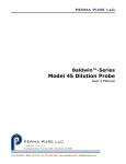
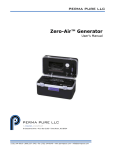
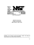
Ambi-GASS™
Gas Analysis Sampling System
User Manual
PERMA PURE
8 Executive Drive
Toms River, N.J. 08755
Phone: 800-337-3762
732-244-0010
Fax: 732-244-8140
e-mail: [email protected]
www.permapure.com
TABLE OF CONTENTS
1
Introduction..........................................................................................................................4
2
Ambi-GASS Components....................................................................................................5
2.1 Filter
2.2 Automatic Filter Drain(optional)
2.3 Nafion Dryer
2.4 Ammonia Scrubber(optional)
2.5 Purge Air Eductor(optional)
2.6 Purge Air Dryer(optional)
2.7 Sample Pump(optional)
3
Installation...........................................................................................................................7
3.1 Mounting
3.2 Electrical Connection
3.3 Plumbing
A. Sample Connection
B. Purge Connection
C. Purge Eductor Inlet Connection
D. Filter Drain Connection
4
Start-Up Procedure..............................................................................................................9
4.1 Setup Check
4.2 Purge Air Flow Adjustment
4.3 Purge Air Eductor(optional)
4.4 Automatic Filter Drain(optional)
4.5 Sample Flow
5
Maintenance........................................................................................................................11
5.1 Filter
5.2 Dryer
5.3 Fuse
5.4 Ammonia Scrubber
APPENDIX A - Specifications.........................................................................................................14
APPENDIX B - Dryer Element Replacement..................................................................................15
A. PD Dryer with Two Part End Fittings
B. PD Dryer with One Part Molded Fitting
APPENDIX C - Replacement Parts List for Ambi-GASS..................................................................17
Ambi-GASS User Manual
2
WARNING
Thank you for purchasing sample gas conditioning equipment from Perma Pure LLC. We want your new sample
gas conditioning equipment to operate safely. Anyone who installs or uses this equipment should read this
publication before installing or operating this equipment.
To minimize the risk of potential safety problems, you should follow all applicable local and national codes that
regulate the installation and operation of your equipment. These codes vary from area to area and usually
change with time. It is your responsibility to determine which codes should be followed and to verify the equipment,
installation and operation is in compliance with the latest revision of these codes.
At a minimum, you should follow all applicable sections of the National Fire Code, National Electrical Code, and
the codes of the National Electrical Manufacturer’s Association (NEMA). There may be local regulatory or
government offices that can also help determine which codes and standards are necessary for safe installation
and operation.
Equipment damage or serious personal injury can result from the failure to follow all applicable codes and
standards. We do not guarantee the products described in this publication are suitable for your particular
application, nor do we assume any responsibility for your system design, installation or operation. This product
should not be operated in any manner that is inconsistent with its intended use.
If you have any questions concerning the installation or operation of this equipment, or you need additional
information, please call us at 1-800-337-3762.
TRADEMARKS
This publication is based on information that was available at the time it was printed. At Perma Pure we constantly strive to
improve our products and services, so we reserve the right to make changes to the products and/or publications at any time
without notice and without any obligation. This publication may also discuss features that may not be available in certain
revisions of the product.
Trademarks
Nafion® and Teflon® are registered trademarks of EI DuPont de Nemours
Copyright 1996-2005, Perma Pure LLC All Rights Reserved
Ambi-GASS User Manual
3
1. Introduction
Perma Pure Ambi-GASS sample pre-conditioning systems are designed to prepare ambient gas sample
streams for analysis. The Ambi-GASS system will remove particulate, mists and water vapor without
removing the compounds being monitored. Gas conditioning is accomplished by filtering the sample and
then removing water vapor with a Nafion membrane gas dryer (see Figure 1).
Standard Features Include:
- Filter – Particulate and/or Coalescing
- Perma Pure Nafion Gas Dryer
- Dryer Purge Flow Controls
Options:
- Sample Pump
- Filter Drain
- Ammonia Scrubber
- Heatless Dryer (Purge Air Dryer)
- Purge Eductor
Internal Components
Control Panel
TM
Ambi-GASS
Gas Analysis Sampling System
PURGE AIR FLOW RATE
CAUTION : READ INSTRUCTION
MANUAL BEFORE OPERATING
FILTER DRAIN
TIMER SETTINGS
ON
OFF
30
25
20
15
10
5
10
I
ON
5
U
F US
SE
F US E
0
15
psi
20
25
0
30
E F
OFF
SYSTEM
POWER
FUSE
PRESSURE ADJUSTMENT
FLOWMETER
SUPPLY PRESSURE
Figure 1
Ambi-GASS User Manual
4
2. Ambi-GASS Components
2.1 Filtration
The first step in conditioning the sample is to filter out particulate and aerosols. This
is accomplished by passing the sample through a 1μ filter which has a borosilicate
glass filter element with a fluorocarbon binder. The element is disposable. In
addition to removing particulate, the filter coalesces liquid aerosols and droplets.
Two flow patterns are possible with this filter:
1.
Installed with flow passing from the
outside to the inside of the element, the
element will act as a particulate filter only.
The advantage of this installation is that
collected particulate will build up on the
outside surface of the element, allowing
visual inspection of the element’s condition.
2.
Installed with the flow passing from the
inside of the element to the outside, the
element will act as both a particulate and
a coalescing filter. Figure 2 details the
flow through the filter housing and element.
Figure 2
2.2 Automatic Filter Drain (optional)
If coalescing is anticipated, an automatic filter drain is needed in the system to periodically
remove collected liquid mists (usually acid mists). The automatic drain will operate in a
vacuum or pressurized system.
1. Vacuum Configuration
Collected liquid is withdrawn from the filter drain port by a strong vacuum created
by an eductor expanding compressed air through a venturi. This is done in
cycles, controlled by an adjustable digital timer that switches a solenoid valve
and controlling the compressed air supply.
2. Pressurized Applications
An eductor is not required since a vacuum is not needed to withdraw the
sample. Therefore, condensate withdraw is directly controlled by the solenoid
valve. Cycle times can be varied and will be dependent on the amount of
liquid present in the sample.
2.3 Nafion® Dryer
The Perma Pure Nafion membrane dryer is installed downstream of the filter. As
sample enters the dryer, the flow splits into a number of small diameter Nafion
membrane tubes arranged in a parallel bundle (see Figure 3 on page 6). After the sample
enters one of these tubes it comes in contact with the Nafion membrane walls. The
membrane selectively removes water vapor from the sample by a process of
permeation distillation. Water vapor travels through the tubing walls driven by the
difference in partial water vapor pressure on the opposing sides of the membrane.
As the sample flows from inlet to outlet water is continually removed, reducing the
sample dew point as it travels through the dryer. Dry purge gas enters the dryer at
the sample outlet end and provides a medium for the water vapor from the sample to
be carried away.
Ambi-GASS User Manual
5
Figure 3
It is important that the dryer removes water in the vapor state only to avoid the problems
that arise when the membrane comes in contact with liquid water. If liquid water is
introduced into the dryer, efficiency will decline and the dryer could fail to perform
altogether. The tubing elongates approximately 10% over its dry length when saturated with
liquid water causing the tubing to kink inside the dryer housing, reducing the drying.
2.4 Ammonia Scrubber (optional)
The optional ammonia scrubbing canister must be used when ammonia or urea is used for the
purpose of lowering NOx levels or at any time ammonia is present in the sample stream.
Ammonia salts can deposit in the dryer tubes if not removed and cause permanent loss of
drying efficiency. The ammonia scrubber consists of a polysulfone and 316 SS housing
filled with phosphoric acid impregnated berl saddles. These berl saddles will require
periodic replacement at a frequency dependent on the inlet ammonia concentration.
2.5 Purge Air Eductor (optional)
The eductor will provide the desired vacuum inside the dryer shell to compensate for any
small vacuum that the sample may be under. This is done to prevent the membrane tubes
from collapsing under pressure of the purge air.
2.6 Purge Air Dryer (optional)
If - 40°C dewpoint or drier purge air is not available, a heatless air dryer can be installed in
the Ambi-GASS to dry a compressed air supply. Operation of the heatless dryer is fully
automatic and continuous.
2.7 Sample Pump (optional)
Perma Pure can supply a gas sample pump to draw sample and supply it to the analyzer.
The pump supplies up to 5 liters per minute of sample. Typical pump location is between
the filter and the ammonia scrubber (when installed).
Ambi-GASS User Manual
6
3. Installation
3.1 Mounting
Unit should be shielded from direct rain and snow. Do not install outdoors if
temperature will fall below -10°C.
1.
Arrange system on a vertical surface.
2.
Place mounting feet on each corner of the enclosure with the slotted end protruding
at a 45° angle from the enclosure.
3.
Drop the mounting screw in from the top and tighten into foot.
3.2 Electrical Connection
Model # 110 VAC
220 VAC
1214 Standard Power Cord and Plug Cord with Pigtail Wires
1228 Connect power supply line to terminal block located on bottom of control
enclosure just inside 1/2" conduit hub. See Figure 4 for color coding.
L1
N
G
Figure 4
Ambi-GASS User Manual
7
3.3 Plumbing
A. Sample Connection
1.
Connect sample line to bulkhead fitting (labeled “Sample Gas In”).
2.
Connect sample outlet (labeled “Dry Sample Out”) to sample line going to analyzer.
B. Purge Connection
Instrument Air
The purge air supply must be of instrument grade with a dew point no
higher than –40OC.
1.
Connect purge air line to bulkhead fitting (labeled “Instrument Air Inlet”).
2.
Set instrument /compressed air supply pressure regulator between 30 and
100 psig.
Heatless Dryer (Optional)
1.
Connect purge air line to bulkhead fitting (labeled “Purge Gas Inlet”).
2.
Set air pressure regulator between 60 and 100 psig.
3.
There will be an additional ¼” female NPT bulkhead fitting on bottom of
enclosure for heatless dryer purge air exhaust (labeled “Heatless Dryer
Exhaust”). This will be humid air, and can be vented to atmosphere or piped
to a remote location.
C. Purge Eductor Inlet Connection (optional)
Connect air supply line to bulkhead fitting labeled “Compressed Air Inlet”.
D. Filter Drain Connection (optional)
Connect line from eductor outlet to designated collection/exhaust basin containing
acid absorption media to prevent release of exhaust to surrounding. ¼” I.D. tubing
can be used for runs up to 10 feet, or larger I.D. tubing for longer exhaust lines. Line
should not restrict purge flow.
Ambi-GASS User Manual
8
4. Start-Up Procedure
4.1 Setup Check
1.
Check electrical, sample, purge and drain connections have been made.
2.
Turn on instrument and/or compressed air to system.
4.2 Purge Air Flow Adjustment
Purge air to dryer is controlled by regulator and flowmeter combination on control panel.
Pressure setting are as follows:
1.
With optional filter drain – Set pressure to aprox. 10 psig.
2.
Without filter drain – Set pressure to aprox. 20 psig
3.
Adjust purge air flow to 1 1/2 to 2 times sample flow.
4.3 Purge Air Eductor (optional)
Adjust eductor regulator until vacuum gauge reads about 2-5 inches of mercury.
Re-adjusted each time changes are made to purge flow rate or purge pressure.
Ambi-GASS User Manual
9
4.4 Automatic Filter Drain (optional)
The automatic filter drain is controlled by a repeat-cycle-timer that operates a solenoid
valve. There are two DIP switches located on the timing device that control the drain and
cycle times located on backside of control panel.
Factory setting: drain for 0.1 minute once every 24 hours.
Drain time (left DIP switch)
0.1 minutes (1st switch “ON” – all others “OFF”)
to
102.3 minutes (all switches “ON”)
Cycle time (right DIP switch)
1 hours (1st switch “ON” – all others “OFF”)
to
1023 hours (all switches “ON”)
1.
Adjust purge air pressure regulator to about 15 psig.
Under Vacuum: Purge air regulator will control air pressure to eductor of the
automaticfilter drain. The regulator must be set to provide ample vacuum to remove
filter condensate but not excessive enough to cause an interruption in sample flow
to analyzers.
Under Positive Pressure: Condensate drain flow is directly controlled by a
solenoid valve. When solenoid valve is actuated (opened), positive pressure in filter
housing purges condensate out of the system through the drain line.
2.
Initially adjust DIP switches on the drain timer to drain for 6 seconds every 24 hours.
The time on the switches is additive. So, left switch should have only the top 0.1 min.
switch in the “ON” position and the right switch should have the 8 and 16 hr. switches
in the “ON” position. These time periods may need further adjustment after system
has been in operation for a while.
4.5 Sample Flow
Sample may be turned on at this time. Adjust flowmeter to desired flowrate.
Ambi-GASS User Manual
10
5. Maintenance
5.1 Filters
If the system is fitted with a pre-filter, it should be checked regularly to ensure that the element is in
good condition. If the element appears to be dirty or begins to cause a flow restriction in the
system, it should be replaced.
Filter Element Replacement
1.
Loosen bolt on bottom of filter (see Figure 5).
2.
Gently pull apart assembly and remove old element.
3.
Place new element into grooves in top and bottom of housing.
4.
When re-assembling, inspect for o-rings on top and bottom pieces and on center bolt.
5.
Install glass shell onto bottom piece
6.
Place new element in groove in bottom piece. Be sure that element is seated correctly and
parallel to glass shell.
7.
Carefully mate bottom assembly onto top piece. Slight twisting motion may be required to
allow shell to slip over o-ring seal.
8.
Visually make sure element is seated correctly in top groove.
9.
Replace bolt through hole in bottom piece and screw clockwise into top piece. Do not to
over-tighten center bolt or damage may occur. It should be just tight enough as to not
vibrate loose. Over-tightening will not help filter to seal.
Top Cap
O-ring
Shell
Bottom Cap
Bolt
Figure 5
Ambi-GASS User Manual
11
5.2 Dryers
Under normal conditions Perma Pure dryers require little maintenance and can last for several
years. However, if there is no pre-filter and tubing becomes clogged or saturated with water, dryer
may require cleaning or repair. When disassembling the dryer, note that end fittings on the PDSERIES dryer can be easily rotated on shell tube. This rotation should be avoided to prevent
twisting membrane tubes inside the shell.
Dryer Element Replacement:
1.
2.
3.
Take dryer assembly out of unit by unscrewing 4 screws on heater block, 4 screws on
bottom of unit along with 2 allen hex head screws.
Loosen all compression fittings connecting to dryer.
Refer to Appendix B for Dryer Element Replacement.
When connecting any fittings to purge ports of dryer, be sure not to tighten threaded fittings
more than 5 turns. Additional turns may cause fitting to damage element header just below.
5.3 Fuse
Fuse Replacement - The fuse is located on or in the control enclosure.
To remove the fuse:
1.
2.
3.
Turn cap marked “FUSE” counter-clockwise ¼ turn and the fuse holder will come out.
Remove blown fuse and replace with one of equal amperage rating. The standard fuse is a
BUSS type AGC or equivalent.
After installing correct replacement fuse, re-install fuse holder by pressing inward and
twisting 1/4 turn clockwise.
Ambi-GASS User Manual
12
5.4 Ammonia Scrubber
Media Replacement:
When deposits are visible 75% of the way up the length of the scrubber, scrubbing media needs to
be replaced.
1.
2.
3.
4.
5.
6.
7.
8.
9.
10.
11.
12.
13.
Unscrew thumbscrew on bottom of housing (see Figure 6).
Swing yoke to one side.
Separate housing and bottom cap as an assembly from top cap.
Remove spring and top screen.
Remove old media and dispose of properly (housing may be rinsed with soapy water to
clean).
Fill housing with 50cc of Berl Saddles (tap housing to allow material to settle).
Pour 150cc of Scrubbing Media (tap housing to allow material to settle).
Replace stainless steel screen on top of media.
Replace spring on top of screen.
Clean o-rings on shell and inside top manifold (replace if necessary).
Place center tube into o-ring seal in top cap.
Push and twist to seal housing around o-ring.
Replace yoke and tighten thumbscrew finger tight (do not overtighten doing so may
cause housing to crack and cause leakage).
BURL SADDLES
& MEDIA
YOKE
THUMB SCREW
Figure 6
Ambi-GASS User Manual
13
APPENDIX A - Specifications
MAXIMUM SAMPLE FLOW RATE:
0 TO 20 LITERS/MIN
MAXIMUM GAS SAMPLE WATER VAPOR CONTENT:
NON CONDENSING AT
AMBIENT TEMPERATURE
SOLUBLE GAS REMOVAL RATES:
NO, NO2
SO2
CO, CO2
H2S, HCl
MAXIMUM GAS SAMPLE INLET PRESSURE:
80 PSIG
MINIMUM GAS SAMPLE INLET PRESSURE:
5" H2O VACUUM
GAS SAMPLE INLET FITTINGS:
1/4" or 3/8" TUBING FITTINGS
GAS SAMPLE OUTLET FITTINGS:
1/4" or 3/8" TUBING FITTINGS
AIR REQUIREMENTS:
PURGE AIR -40°C DEW POINT
MAXIMUM ONE (1) CFM
ELECTRICAL REQUIREMENTS:
- for units with automatic drain
0% loss
0% loss
0% loss
0% loss
10 WATTS
FUSE:
0.5 AMP BUSS TYPE AGC
OR EQUIVALENT
ENCLOSURE:
NEMA 4X, FIBERGLASS WITH
POLYCARBONATE COVER
DIMENSIONS:
26" HIGH X 11" WIDE X 8" DEEP
OPERATING ENVIRONMENT:
-20°C TO 40°C AMBIENT TEMP.
0 TO 95% R.H.
Ambi-GASS User Manual
14
APPENDIX B - PD Dryer Element Replacement
A. PD Dryer with Two Part End Fittings
Tools Needed:
-Allen wrench 3/32
-Snap ring pliers
-Pair of lightweight gloves
1.
2.
3.
4.
5.
6.
7.
8.
Hold coupling and shell with one hand, and remove front nut on each end with the other
(see Figure below).
Loosen set screws on both ends of couplings using Allen wrench.
Remove snap ring from both sides using snap ring pliers.
Put on pair of lightweight gloves(protects membrane tubing from skin oils contaminating
surface and reducing drying efficiency).
Pull element header out of housing on one side to expose o-ring. Do not rotate more than
10° in either direction.
Remove inner o-ring.
Gently pull element out other end.
Reverse procedure to assemble dryer.
Ambi-GASS User Manual
15
B. PD Dryer with One Part Molded Fitting
TO DISASSEMBLE DRYER
Tools Needed:
- Phillips head screwdriver
- unsharpened pencil with eraser
1.
2.
3.
4.
5.
6.
7.
Loosen locking screws on both ends of dryer.
Insert eraser end of pencil into one sample port
until it rests on tube header face (see Figure on right).
Hold dryer vertically and place other end of pencil
down onto a hard, slip resistant surface.
While supporting shell tube, push lower end fitting down
with consistent pressure until it slips off shell tube.
Do not attempt to pull fitting from shell tube; doing
this is likely to damage dryer element tubing.
Repeat steps 2-4 for other end.
Remove one o-ring from tube header .
Pull tube element from opposite end of dryer.
Tube Header
TO ASSEMBLE DRYER
Tool Needed:
- Phillips head screwdriver
1.
2.
3.
4.
5.
6.
7.
8.
Install one thick o-ring onto grooved tube header .
Slip opposite tube header into dryer shell.
Install other thick o-ring onto groove.
Push one thin o-ring into groove inside coupling (for SS
and AL shells slip o-ring on shell across two holes).
Firmly push coupling over tube header.
Align purge port with hole in shell tube (see Figure on right).
Tighten locking screws until underside of screw head
contacts top of boss.
Repeat steps 4-7 for opposite end.
Ambi-GASS User Manual
Check for
Alignment
Sample
Port
16
APPENDIX C - Replacement Parts List for Ambi-GASS
Part Number
AG-FM
AG-PR
AG-PG-0-30
AG-VG-0-60
Description
Flow Meter, purge gas (0-60 L/min)
Pressure Regulator, purge gas or eductor
Pressure Gage, purge gas (0-30 PSI)
Vacuum Gage, purge eductor (0-30"Hg)
AG-DC
PD-50T-24E
PD-100T-24E
PD-200T-24E
Mounting Clamps for Dryer (specify dryer model)
50 Tube dryer replacement element, 24" long, includes o-rings
100 Tube dryer replacement element, 24" long, includes o-rings
200 Tube dryer replacement element, 24" long, includes o-rings
FF-250-E-2.5G
FF-250-G
FF-250-3
AS-200-08-EB
Replacement filter element
Replacement glass shell
Replacement o-ring set, set of 3
Media replacement for ammonia scrubber, bulk supply, 5 fillings
Ambi-GASS User Manual
17