1
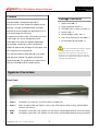
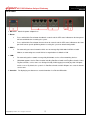
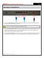
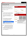
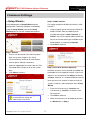
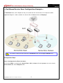
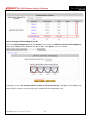
4ipnet HSG1200
Quick Installation Guide
V1. 0 0
4ipnet H
S G 1 2 0 0 W ir e le s s H o ts p o t G a te w a y
4ipnet H S G 1 2 0 0
Q u ic k I ns ta l l a tio n G u id e
EE
ENGLISH
Copyright N otic e
This document is protected by USA copyright laws and other laws and is the property of
4 I P N E T, I N C . Y ou may not copy, reproduce, distribute, publish, display, perform, or
modify any part of this publication in any form or by any means without prior written
permission from 4 I P N E T, I N C . Y ou may not alter or remov e any copyright or other notice
from copies of the content. All other brand and product names are claimed or
registered mark s of their respectiv e companies or organiz ations.
All rights reserv ed.
F CC Ca u tion
This eq uipment has been tested and prov en to comply with the limits for a class B
digital dev ice, pursuant to part 1 5 of the F C C
R ules. These limits are designed to
prov ide reasonable protection against harmful interference in a residential installation.
This eq uipment generates uses and can radiate radio freq uency energy and, if not
installed and used in accordance with the instructions, may cause harmful interference
to radio communications. H owev er, there is no guarantee that interference will not
occur in a particular installation. I f this eq uipment does cause harmful interference to
radio or telev ision reception, which can be determined by turning the eq uipment off
and on, the user is encouraged to try to correct the interference by one or more of the
following measures:
R eorient or relocate the receiv ing antenna.
C onnect the eq uipment into an outlet on a circuit different from that to which the
I ncrease the separation between the eq uipment and receiv er.
receiv er is connected.
C onsult the dealer or an ex perienced radio/ TV technician for help.
4ipnet H
4ipnet H S G 1 2 0 0
Q u ic k I ns ta l l a tio n G u id e
EE
ENGLISH
S G 1 2 0 0 W ir e le s s H o ts p o t G a te w a y
Preface
Package Contents
4ipnet HSG1200 Wireless Hotspot Gateway in 19”
rack-mountable is designed to provide an
1. 4ipnet HSG1200 x 1
easy-to-use, all-in-one solution for hotspot service
2. Quick Installation Guide x 1
providers. A single HSG1200 enables a hotspot
3. CD-ROM (with User Manual and QIG) x 1
provider to service multiple hot-spot franchises in a
4. Power Cord x 1
mall area through the feature of
5. Power Adaptor (12DC, 2A) x 1
multiple-Service-Zone. Each service zone can have
6. Cross-over Ethernet RJ-45 Cable x 1
its own login skin and an independent SSID.
7. RS-232 DB9 Console Cable x 1
HSG1200 is also ideal for hospitality application.
For example, a hotel can use the service zone
feature to separate the privileges of staff, guest, and
It is recommended to keep the original
packing material for possible future
shipment when repair or maintenance is
required. Any returned product should be
packed in its original packaging to prevent
damage during delivery.
VIP usage for accessing Internet.
This Quick Installation Guide provides instructions
and reference materials for getting started with
4ipnet HSG1200. This guide will also show how to
connect HSG1200 to other network devices.
System Overview
Front Panel
1. Power
ON indicates the power on, and OFF indicates the power off.
2. Status
Power and Status both ON indicate system ready, OFF indicates BIOS running, and BLINKING
indicates OS running.
3. WAN
ON indicates connection, OFF indicates no connection, and BLINKING indicates data transmitting.
4. LAN
ON indicates connection, OFF indicates no connection, and BLINKING indicates data transmitting.
C o p y r i g h t © 4I P N E T , I N C . A l l r ig h ts r es er v ed .
4ipnet H
S G 1 2 0 0 W ir e le s s H o ts p o t G a te w a y
4ipnet H S G 1 2 0 0
Q u ic k I ns ta l l a tio n G u id e
EE
ENGLISH
Rear Panel
1. DC+12V Attach the power adaptor here.
2. Reset
•
Press and hold the Reset button for about 5 seconds and the LED status indicator on the front panel
will start to blink before restarting the system.
•
Press and hold the Reset button for more than 10 seconds and the LED status indicator on the front
panel will start to speed up blinking before resetting the system to default configuration.
3. WAN
•
For connecting to external networks which are not managed by HSG1200 via ADSL or Cable
Modem, or connecting to a certain LAN of an organization via Switch or Hub.
4. LAN
•
For connecting to the networks managed by HSG1200, such as client networking devices.
•
HSG1200 supports Service Zone function including Port-Based mode and Tag-Based mode. Under
Tag-Based mode, service zones are distinguished by VLAN tagging instead of physical LAN ports,
and vise versa. By default, the system is in Port-Based mode and all LAN ports are set to the default
service zone.
5. Console For displaying text data on an extended monitor via a RS-232 DB9 cable.
C o p y r i g h t © 4I P N E T , I N C . A l l r ig h ts r es er v ed .
4ipnet H
S G 1 2 0 0 W ir e le s s H o ts p o t G a te w a y
4ipnet H S G 1 2 0 0
Q u ic k I ns ta l l a tio n G u id e
EE
ENGLISH
H a rd wa re I n sta l l a tio n
1. Connect the Power adapter to the power socket on the rear panel. The Power LED on the front panel
should be ON to indicate a proper connection.
Using a non-certified power adapter may damage this system.
2. Connect an Ethernet cable to WAN1 Port on the rear panel. Per your needs, connect the other end of the
cable to a networking device such as ADSL modem, cable modem, switch or hub. The WAN1 LED
indicator should be ON to indicate a proper connection.
3. Connect an Ethernet cable to any LAN Port on the rear panel. Connect the other end of the cable to a PC
for configuring the HSG1200 system. The LED indicator should be ON to indicate a proper connection.
C o p y r i g h t © 4I P N E T , I N C . A l l r ig h ts r es er v ed .
4ipnet H
4ipnet H S G 1 2 0 0
Q u ic k I ns ta l l a tio n G u id e
EE
ENGLISH
S G 1 2 0 0 W ir e le s s H o ts p o t G a te w a y
G ettin g Sta rted
4ipnet HSG1200 supports web-based configuration.
Upon the completion of hardware installation,
HSG1200 can be configured through a PC by using
its web browser with JavaScript enabled such as
Internet Explorer version 6.0.
Steps:
1.
4.
Set DHCP in TCP/IP of the administrator PC
The Home Page will appear after a
successful login.
to get an IP address dynamically. Connect the
PC to any LAN Port of HSG1200. An IP
address will be assigned to the PC
automatically via the HSG1200 built-in DHCP
server.
2.
Launch a web browser to access the web
management interface of HSG1200 by
entering “https://192.168.1.254” or
“http://192.168.1.254” in the address field.
Note:
Note:
3.
“https” is used for a secured connection.
The following Administrator Login Page will
then appear. Enter “admin” (the default value)
in the Username and Password fields, and
then click Login to log in.
C o p y r i g h t © 4I P N E T , I N C . A l l r ig h ts r es er v ed .
To logout, simply click the Logout
button at the upper right hand corner
of the interface to return to the
Administrator Login Page.
4ipnet H
4ipnet H S G 1 2 0 0
Q u ic k I ns ta l l a tio n G u id e
EE
ENGLISH
S G 1 2 0 0 W ir e le s s H o ts p o t G a te w a y
C o mmo n Settin g s
< Setup Wizard >
Step 2: WAN1 Interface
HSG1200 provides a Setup Wizard for quick
For setting up both wired WAN and wireless LAN
configuration. To quickly configure HSG1200 by
functions:
using the Setup Wizard, click on the Setup
•
Wizard button to start the configuration process.
Select a proper type of Internet connection for
WAN1 interface from the following three
available connections: Static, Dynamic, or
PPPoE. Your ISP or network administrator can
advise on the connection type available to you.
Below depicts an example for Dynamic.
•
Click Next to continue.
Step 1: General
•
Enter a new password in the New Password
field, and re-enter it again in the Verify
Password field (a maximum of 20 characters
and no spaces allowed in between).
•
•
Select an appropriate time zone from the Time
Zone drop-down list box to set up the system
Step 3: Local User Account (Optional)
time.
New local accounts can be created and added into
Click Next to continue.
the database via this optional function. If local user
accounts are not required, click Skip to go directly
to Step 4. However, It is recommended to create at
least one local user account in order to verify the
system‘s readiness upon completion of this Setup
Wizard.
•
Enter the Username (e.g. “testuser) and
Password (e.g. “testuser”) to create a new
local account.
For security concern, it is strongly
recommended to change the
administrator's password
C o p y r i g h t © 4I P N E T , I N C . A l l r ig h ts r es er v ed .
•
Click Next to continue.
•
More local accounts can be added by clicking
the Back button in Step 4.
4ipnet H
4ipnet H S G 1 2 0 0
Q u ic k I ns ta l l a tio n G u id e
EE
ENGLISH
S G 1 2 0 0 W ir e le s s H o ts p o t G a te w a y
Step 4: Confirm and Restart
•
Note:
Click Finish to save current settings and
restart the system.
•
The system is trying to locate a DNS
server at this stage. Therefore, a
longer startup time is required if the
configured DNS cannot be found.
When the following Administrator Login Page
appears, it means the restart process is now
completed.
•
A confirmation dialog box will then appear.
Click OK to continue.
•
A Confirm and Restart message will appear
on the screen during the restarting process.
Please do not interrupt the system until the
Administrator Login Page appears.
C o p y r i g h t © 4I P N E T , I N C . A l l r ig h ts r es er v ed .
4ipnet H
4ipnet H S G 1 2 0 0
Q u ic k I ns ta l l a tio n G u id e
EE
ENGLISH
S G 1 2 0 0 W ir e le s s H o ts p o t G a te w a y
< User Login >
Note:
1.
HSG1200 supports multiple authentication
options including built-in local user database
and external authentication database (e.g.
RADIUS). The system will automatically
identify which authentication option is used
from the full username entered.
2.
The format of a full (valid) username is
userid@postfix, where “userid” is the user
ID and “postfix” is the name of the selected
authentication option.
3.
Exception: The postfix can be omitted only
when the default authentication option is
used. For example, “LOCAL” is the default
authentication option at this system;
therefore, you may enter either “testuser” or
“testuser@local” in the Username field.
To verify whether the configuration of the new local
user account(s) created via the Setup Wizard has
been completed successfully:
1. Connect a client device (e.g. laptop, PC) to any
LAN Port of HSG1200. The device will obtain
an IP address automatically via DHCP.
2. Open a web browser on a client device, access
any URL, and then the default User Login
Page will appear.
Congratulation!
3. Enter the Username and Password of a local
The Login Success Page will appear after a client
user account previously generated via Setup
has successfully logged into HSG1200 and has
Wizard (e.g. “testuser@local” as the
been authenticated by the system.
Username and “testuser” as the Password);
The appearance of Login Success Page means
then Click Login.
that HSG1200 has been installed and configured
properly.
C o p y r i g h t © 4I P N E T , I N C . A l l r ig h ts r es er v ed .
4ipnet H
S G 1 2 0 0 W ir e le s s H o ts p o t G a te w a y
4ipnet H S G 1 2 0 0
Q u ic k I ns ta l l a tio n G u id e
EE
ENGLISH
Servic e Z o n e – D ep l o ymen t E x a mp l e
< Small and Mid-size Business Network Environment >
In a Small and Mid-size Business (SMB) network environment, devices such as switches, hubs, and access points
are commonly used, and Internet connection is usually via an ADSL or a cable modem. HSG1200 uses virtual LAN
(VLAN) technology to partition one physical network under its control into nine logical virtual networks, called
Service Zones, including one untagged zone and eight tagged zones. The untagged zone is also referred as the
Default Service Zone in this system, which is always enabled. On the other hand, the other four tagged zones can
be enabled or disabled respectively. By default, port-based configuration is used and all of the four physical LAN
ports are set to use the Default Service Zone.
The figure below demonstrates an example of the SMB network deployed with HSG1200.
Example: Managed network deployment
C o p y r i g h t © 4I P N E T , I N C . A l l r ig h ts r es er v ed .
4ipnet H
S G 1 2 0 0 W ir e le s s H o ts p o t G a te w a y
4ipnet H S G 1 2 0 0
Q u ic k I ns ta l l a tio n G u id e
EE
ENGLISH
< Port-Based Service Zone Configuration Example >
In Port-Based mode, each LAN port can only serve traffic from one Service Zone. An example of network
application diagram is shown as below: one Service Zone for Guest and one for Employee.
The switches deployed under HSG1200 in Port-Based mode must be Layer 2 switches only.
Configuration Steps:
Step 1: Configure Service Zone 1 for Guest
Assume that LAN1 is assigned to the Service Zone 1 (SZ1) for Guest. Click the System menu and select the
Service Zones tab. Click Configure of SZ1.
C o p y r i g h t © 4I P N E T , I N C . A l l r ig h ts r es er v ed .
4ipnet H
S G 1 2 0 0 W ir e le s s H o ts p o t G a te w a y
4ipnet H S G 1 2 0 0
Q u ic k I ns ta l l a tio n G u id e
EE
ENGLISH
Step 2: Configure Basic Settings for SZ1
Check the Enabled radio button of Service Zone Status to activate SZ1.
Enter a name for SZ1 (e.g. “Guest”) in the Service Zone Name field.
Step 3: Configure Authentication Settings for SZ1
Check the Enabled radio button to enable Authentication Required for the Zone.
Check the Default button and Enabled box of Guest Users to set ONDEMAND authentication method as default.
Disable all other authentication options. Then, click Apply to activate the settings made so far. A warning message
“You should restart the system to activate the changes.” will appear at the bottom of the page. Do NOT restart
the system until you have completed all the configuration steps.
C o p y r i g h t © 4I P N E T , I N C . A l l r ig h ts r es er v ed .
4ipnet H
S G 1 2 0 0 W ir e le s s H o ts p o t G a te w a y
4ipnet H S G 1 2 0 0
Q u ic k I ns ta l l a tio n G u id e
EE
ENGLISH
Step 4: Configure LAN Port Mapping for SZ1
Select the LAN Port Mapping tab from the System menu to enter the LAN Ports and Service Zone Mapping
page. Select Guest from the drop-down list box of LAN1. Click Apply to save the selection.
A warning message “You should restart the system to activate the changes.” will appear at the bottom of the
page. Do NOT restart the system until you have completed all the configuration steps.
C o p y r i g h t © 4I P N E T , I N C . A l l r ig h ts r es er v ed .
4ipnet H
S G 1 2 0 0 W ir e le s s H o ts p o t G a te w a y
4ipnet H S G 1 2 0 0
Q u ic k I ns ta l l a tio n G u id e
EE
ENGLISH
LAN1 is now configured for Guests.
Step 5: Configure Service Zone 2 for Employee
Assume that LAN2 is assigned to the Service Zone 2 (SZ2) for Employee. Select the Service Zones tab and click
Configure of SZ2.
Step 6: Configure Basic Settings for SZ2
Check the Enabled radio button of Service Zone Status to activate SZ2.
Enter a name for SZ2 (e.g. Employee) in the Service Zone Name field.
C o p y r i g h t © 4I P N E T , I N C . A l l r ig h ts r es er v ed .
4ipnet H
S G 1 2 0 0 W ir e le s s H o ts p o t G a te w a y
4ipnet H S G 1 2 0 0
Q u ic k I ns ta l l a tio n G u id e
EE
ENGLISH
Step 7: Configure Authentication Settings for SZ2
Check the Enabled radio button to enable Authentication Required for the Zone.
Check the Default button and Enabled box of Server 1 to set LOCAL authentication method as default. Disable all
other authentication options. Then, click Apply to activate the settings made so far. A warning message “You
should restart the system to activate the changes.” will appear at the bottom of the page. Do NOT restart the
system until you have completed all the configuration steps.
Step 8: Configure LAN Port Mapping for SZ2
Select the LAN Port Mapping tab from the System menu to enter the LAN Ports and Service Zone Mapping
page. Select Employee from the drop-down list box of LAN2. Click Apply to save the selection.
C o p y r i g h t © 4I P N E T , I N C . A l l r ig h ts r es er v ed .
4ipnet H
S G 1 2 0 0 W ir e le s s H o ts p o t G a te w a y
4ipnet H S G 1 2 0 0
Q u ic k I ns ta l l a tio n G u id e
EE
ENGLISH
A warning message “You should restart the system to activate the changes.” will appear at the bottom of the
page. Click the hyperlink of Restart to restart the system and activate all configurations.
Please do not interrupt the system during the restarting process.
Once the settings of two Service Zones are completed, the configured result will be displayed in the Service Zone
Settings page: SZ1 and SZ2 are both enabled.
C o p y r i g h t © 4I P N E T , I N C . A l l r ig h ts r es er v ed .
4ipnet H
S G 1 2 0 0 W ir e le s s H o ts p o t G a te w a y
4ipnet H S G 1 2 0 0
Q u ic k I ns ta l l a tio n G u id e
EE
ENGLISH
For configuration of Tag-based/Port-Based service zone and information, please refer to the
User’s Manual, Appendix D. Service Zone Deployment Example.
P / N : V 10 0 2 0 0 9 0 4 0 8
C o p y r i g h t © 4I P N E T , I N C . A l l r ig h ts r es er v ed .