1
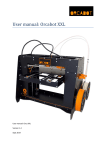
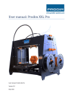
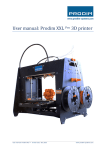
User manual: Orca User manual: Orca Version 1.1 December 2013 Content Content .................................................................................................................................................... 2 1. Setting up the Orca.............................................................................................................................. 3 2. Installing the software ......................................................................................................................... 4 Step 1, driver install............................................................................................................................. 4 Step 2, Pronterface install ................................................................................................................... 4 Step 3, Skeinforge install ..................................................................................................................... 4 Step 4, Repetier install ........................................................................................................................ 5 Arduino ................................................................................................................................................ 5 3. Software applications and usage......................................................................................................... 6 3.1 Repetier host ................................................................................................................................. 6 3.2 Skeinforge ...................................................................................................................................... 8 4. Printing .............................................................................................................................................. 10 4.1 Printer interface printing ............................................................................................................. 10 4.2 Replacing material ....................................................................................................................... 13 5. Skeinforge profile settings................................................................................................................. 14 User manual: Orca - version 1.1 2 1. Setting up the Orca After building or unpacking the Orca, the next step is setting up the printer. A few things are important: - The Orca must be placed on a smooth and level surface There must be an electric socket, recommended is a socket with an on/off switch It is recommended to choose a room or place which has a decent ventilation The Orca package contains the Orca printer, a USB cable and two power supplies. The USB cable is for connecting the printer to a computer. The two power supplies are for: 1. Heated bed 2. Electronics etc. Before testing and connecting the printer to the computer, choose a solid table or desk, to put the printer on. Switch the machine on by switching on the two power supplies (the Orca itself doesn’t have an On/Off switch) and connect the Orca with a computer via the USB cable. The computer will detect a new USB device on one of the COM ports. User manual: Orca - version 1.1 3 2. Installing the software Windows only, there is also an Apple OS package. On the Orcabot website you can download the software package called one big zip “PrinterSoftware-v02a_16-11-2012.zip (168M)”. The file contains: - 1-DRIVER-INSTALL 2-ARDUINO-FIRMWARE 3-PRONTERFACE-INSTALL 4-SKEINFORGE-INSTALL 5-REPETIER-INSTALL 6-TESTPRINTS-STL-GCODES Unpack the whole zip in a folder, for example C:\ Orcabot\Software. Step 1, driver install Open the folder with all the unpacked files in it. First open “1-DRIVER-INSTALL”. Then open the file “FTDI_win7_XP_VISTA-2K_x64_x32”. This folder contains the file “CDM20802_Setup”, run this file twice. The second time a command screen will pop up. Step 2, Pronterface install Open the “3-PRONTERFACE-INSTALL” folder. This folder contains 5 subfolders. - 01_python272 02_pyserial-25 03_wxpython-28 04_pyreadline17 05_Printrun First open “01_puthon272”. The folder contains the file “python-2.7.2”, install it. Python is a program that allows to open “.py” files. Second, open the subfolder “02_pyserial-25”, it contains the file “pyserial-2.5.win32”, install it. Third, open the subfolder “03_wxpython-28”, it contains the file “wxpython2.8-win32-unicode2.8.12.0-py27”, install it. After the installation a command screen will pop up for a few seconds. Fourth, open the subfolder “04_pyreadline17”, it contains the file “pyreadline-1.7.win32”, install it. If the four steps are done correctly, a check can be done to make sure everything did go well. Open subfolder “05_Printrun” and run the file “pronterface.py”. The printer interface will open and the installation has gone well. Step 3, Skeinforge install The folder “4-SKEINFORGE-INSTALL” contains two zip files. First unzip the “sf50_zipped_reprap_python_beanshell”. Open the folder called “50_reprap_python_beanshell”, User manual: Orca - version 1.1 4 open “skeinforge_application” folder. Run “skeinforge.py” and close it. After doing that, the program will make a .skeinforge folder (hidden) in your user folder, for example: “C:\Users\admin\.skeinforge”. Second open the “4-SKEINFORGE-INSTALL” folder again, and choose “sf50_camiel-settings-profiles10-11-2012.zip”. Unpack the “.skeinforge” folder and copy the one in the user folder. In this way a lot of profiles are already loaded in the skeinforge program for printing. Make sure you have removed all old versions of Skeinforge before. Step 4, Repetier install Open the folder “5-REPETIER-INSTALL”, select the “setupRepetierHost_0_74” and install it. With the Repetier host, .STL files can be loaded, printing beds can be made, files can be sliced and saved as gcode files for printing. Arduino Arduino can be used for updating the firmware. Normally, the firmware is already installed on the printer. User manual: Orca - version 1.1 5 3. Software applications and usage Before anything can be printed, a 3D file must be exported to or saved as a “.STL” file. These files are suitable for 3D printing. Make sure when saving the file, that the Z-axis is pointing in the right direction (UP). 3.1 Repetier host Open the Repetier host. The following screen will pop up: In Repetier STL files can be loaded and will be shown in 3D. Just click on the load button (or “Add object”) and choose the wanted STL file or files. Everytime when a new object is loaded, this will be placed automatticaly in the screen and will be show in the list of STL objects. It is also possible tot manually move them with the mouse, or use: “Center object”. There is also the possibility to scale the models or place/rotate them with coordinates. After that, the right size for the printing range must be filled in. Select in top of the screen “Config” “printer settings”. The dialog wil pop up with Printer settings. Choose the third tab “Printer shape” and fill in the dimensions. For the Orca the right settings are: 250mm x 220mm x 190mm. Save the changes and apply. User manual: Orca - version 1.1 6 After placing the object choose the tab “slicer”. In this screen Skeinforge can be activated and profiles can be choosen. After choosen the right profile, press the big button in top “slice with Skeinforge”. Depending on how big the object is, and how fast the computer is, it can take some time (+/- 1 to 5 min). After the slicing is done, the program will automatically change to the tab G-code. In the object screen a blue “layered” object will show up. In the tab under the G-code “visualization” can be selected. In this way the object can be seen layer by layer. So the differences between profiles and alternations can be checked. Also the blue lines indicate the exact printing of the printer itself. If the model is correctly sliced, press the save button and save it as a G-code file. User manual: Orca - version 1.1 7 3.2 Skeinforge In Skeinforge profiles can be altered and changed to the optimal settings or requested settings per user. Simply open the Skeinforge application or select the “configure” button in the Repetier host in the “slicer tab” menu. The Skeinforge program has a lot of possibilities. Make sure that the setting for “Profile type” is “Extrusion”. Underneath there are 5 tabs: - Analyze Craft Help Meta Profile First select the TAB Profile and choose a profile, for instance, 025L. Then type in a name for a new profile so changes can be made and tested without “ruining” the original profile. After typing in a name, select “Add Profile” Then select the profile in the “Profile Selection box” and choose the tab “Craft”. Skeinforge automatically saves changes, so always use test profiles to test with. User manual: Orca - version 1.1 8 In the tab “Craft” a lot of functions can be seen. The most important are Carve, Fill, Raft and Speed. These are the main settings for printing. Every time an option is selected, there will also be a question mark behind the option. The question mark is a link to an internet wiki source for help and explaining every function. There are a lot of profiles already in the program after installing the software and profiles. But still, this is only a basic set up. Try to make extra test profiles and see what the differences are while printing the same object. Again, if a profile is made, choose it in Repetier host and slice the object with that profile and save it as a G-code. User manual: Orca - version 1.1 9 4. Printing 4.1 Printer interface printing Before printing, the Orca must be switched on and connected to a computer via the USB cable. If that is done open the printer interface. Go to the folder “3-PRONTERFACE-INSTALL” “05_Printrun” and select “pronterface.py”. The printer interface will be opened. When opening this screen for the first time, please fill in some settings. First set fill in the correct COM-port settings in the left top corner. Normally when starting the software when the Orca is already switched on, the COM-port will automatically detected. Set the Baudrate to 250.000. At last press the button: “Connect”. After the printer is connected the main printersettings will appear in the text box. The big “Radar” with the arrows are for manual control of the printer. In the corners you can find the home buttons (homeX, homeY, homez and homeALL). Be carefull! Only use homeZ / HomeALL when the Z-is calibrated. Try some arrows and make some moves to make sure that the printer is online and correctly connected. Now some more settings must be changed. In the bottom of the screen two boxes “Extrude” and “Reverse” can be seen. Next to these buttons you can fill in the length and speed for extruding / reversing. The length value is 300 for default. Change this to 120, just by typing it in. Also the temperature settings for the heater and bed are default. The temperature settings that Orcabot recommends are: PLA ABS User manual: Orca - version 1.1 Heater 210 – 220 ˚C 250 – 280 ˚C Bed 56 ˚C 120 ˚C 10 Now we are going to load a G-code file. In the text box the amount of layers is shown, also the estimated printer time. After that choose the correct settings for the temperature en press the set button. With the check temp button, temperatures can be checked and will be shown in the two bars bottom of the screen. You can also use the Monitor printer function. If the temperature is reached, the printer is almost ready for printing, but first manually feed the extruder with some material. Use the big wheel to feed the extruder and hold the material wire with the other hand, feed it until a good amount of material is flowing through the extruder underneath. After this, use a tweezer to remove the material. Warning: the heater is very hot, so don’t touch it with bare hands! Warning: never touch the printer bed or extruder with bare hands! Always use tweezers or pliers to remove prints from the bed. If the bed is touched with bare hands, it’s possible that the bed lose its cohesion. If so, then degrease the bed with acetone. If this is done, press print in “Printer interface”. User manual: Orca - version 1.1 11 While printing, it’s always very important to check the first layer and amount of printed material. With this wheel on the Z-axis, the height of the bed can be changed (this is only useful for the first layer while printing). Check the line of material. If it’s too thin turn the wheel clockwise to raise the bed a bit. Do this until the lines are completely closed. If the lines are too thick and the material is really “sweeping up”, then turn the wheel counter clockwise to lower the bed a bit. The automatic homing of the bed and machine can also be changed with the bolt holding the Z-axis homing on the front of the machine. If the machine is always too high or too low, then adjust the bolt by turning them. In this way, the homing is physically changed. But always check the first layer to make sure. After printing, the machine will automatically cool of and lower and move the bed away from the extruder head. Wait for the machine to cool off for a bit and than remove the printed object. Reminder, never touch the bed of extruder with bare hands. Use pliers or tweezers for removing parts (not manually, otherwise you need to degrease again). User manual: Orca - version 1.1 12 4.2 Replacing material If the spool with material is (almost) empty, or when another material or color is wanted, it is time to replace the spool. Switch on the printer and run Printer interface. Switch on the heater and wait till it has reached its temperature. Try to leave min. 1 cm filament sticking out. After that, reverse the extruder by turning on the big gear and remove the old filament which was in the extruder. After that insert the new filament. In case, filament runs out during a print, press “Pause”and unscrew the four bolts and remove the part in front of it. Use the wheel attached on the extruder to remove the material from the extruded. Then replace the spool of material with the new material and place wire through the tube and also through the little hole on top of the extruded. Guide via the extruded wheel into the actual heater. Manually add some material and push it through the extruded until some material comes out underneath of it. Place back the part with the four screws and tighten it until the material can be extruded by only using the wheel. It it’s done correctly, the printer itself can extrude the material. After doing so, remove the leftovers from the nozzle underneath. User manual: Orca - version 1.1 13 5. Skeinforge profile settings Setting Layer Height Default: 0.4 mm Edge Width over Height 1.8 Feed Rate 16 mm/s Flow Rate Setting 210 (pre-Skeinforge 40, see below for details) Object First Layer 0.4 Object First Layer Feed Rate Perimeter Multiplier 0.4 Object First Layer Flow Rate Infill Multiplier Object First Layer Flow Rate Perimeter Multiplier Perimeter Feed Rate Multiplier 0.4 0.4 1 User manual: Orca - version 1.1 Definition Defines the height of the layers Skeinforge will cut your object into, in the Z direction. This is the most important carve setting, many values in the tool chain are derived from the Layer Height. For a 0.5 mm nozzle usable values are 0.3 mm to 0.5 mm. Note: If you are using thinner layers make sure to adjust the extrusion speed as well. Defines the ratio of the extrusion edge width to the layer height. This parameter tells Skeinforge how wide the edge wall is expected to be in relation to the layer height. Default value of 1.8 for the default layer height of 0.4 states that a single filament edge wall should be 0.4 mm * 1.8 = 0.72 mm wide. The higher the value the more the edge will be inset. A ratio of one means the extrusion is a circle, the default ratio of 1.8 means the extrusion is a wide oval. This is an important value because if you are calibrating your machine you need to ensure that the speed of the head and the extrusion rate in combination produce a wall that is Layer Height * Edge Width over Height wide. To start with Edge Width over Height is probably best left at the default of 1.8 and the extrusion rate adjusted to give the correct calculated wall thickness. Adjustment is in the Speed section with Feed Rate controlling speed of the head in X & Y and Flow Rate Setting controlling the extrusion rate. Initially it is probably easier to start adjusting the flow rate only a little at a time until you get a single filament of the correct width. If you change too many parameters at once you can get in a right mess. Defines the operating feed rate, the speed your printing head moves in XY plane, before any modifiers. Defines the operating flow rate. The default of 210 is for Skeinforge versions before 50. For Skeinforge 50 and later, set the Flow Rate Setting to the same value as the Feed Rate). RapMan uses this parameter to define the RPM of the extruder motor. The extruder motor RPM is flow rate / 10 so if your flow rate is 150.0 that will set the extruder stepper to run at 15 RPM, different printers might read this value differently. Defines the object first layer infill feed rate multiplier. The greater the Object First Layer Feed Rate Infill Multiplier, the thinner the infill (unless you raise Object First Layer Flow Rate Infill Multiplier to match), the lower the Object First Layer Feed Rate Infill Multiplier, the thicker the infill. Defines the object first layer perimeter feed rate multiplier. The greater the Object First Layer Feed Rate Perimeter Multiplier, the thinner the edge (unless you raise Object First Layer Flow Rate Perimeter Multiplier to match), the lower the Object First Layer Feed Rate Perimeter Multiplier, the thicker the edge. Defines the object first layer infill flow rate multiplier. The greater the Object First Layer Flow Rate Infill Multiplier, the thicker the infill, the lower the Object First Layer Flow Rate Infill Multiplier, the thinner the infill. Defines the object first layer perimeter flow rate multiplier. The greater the Object First Layer Flow Rate Perimeter Multiplier, the thicker the edge, the lower the Object First Layer Flow Rate Perimeter Multiplier, the thinner the edge. Defines the ratio of the feed rate of the perimeter (outside shell) over the feed rate of the infill. If you for example set this to 0.8 you will have a "stronger" outside edge than inside extrusion as the outside edge will be printed slower hence better lamination will occur and more filament will be placed there. 14 Perimeter Flow Rate Multiplier 1 Travel Feed Rate 16 mm/s Filament Packing Density 0.85 This is for ABS. User manual: Orca - version 1.1 Defines the ratio of the flow rate of the perimeter (outside shell) over the flow rate of the infill. If you want same thickness of the perimeter but better lamination you need to compensate for the slower feed rate by slowing down the flow rate, but all combinations are possible for different results. Defines the feed rate when the extruder is off (not printing). The Travel Feed Rate could be set as high as the extruder can be moved, it is not limited by the maximum extrusion rate. Defines the effective filament packing density. If you previously used Slic3r, it's the same as Extrusion Multiplier. It's a setting that lets you tweak your esteps (without having the re-flash the firmware) to compensate for different filament hardness’s. The default value assumes you calibrated your e-steps using PLA, but are printing with ABS. If you are printing with the material you calibrated your esteps with, you should set this value to 1. If you later want to print with different materials, you'll need to tweak this value or recalibrate your esteps and update that value in the firmware. The default value is so low for ABS because ABS is relatively soft and with a pinch wheel extruder the teeth of the pinch dig in farther, so it sees a smaller effective diameter. With a hard plastic like PLA the teeth of the pinch wheel don't dig in as far, so it sees a larger effective diameter, so feeds faster, so for PLA the value should be around 0.97. This is with Wade's hobbed bolt. The effect is less significant with larger pinch wheels. Overall, you'll have to find the optimal filament packing density by experiment. 15