1
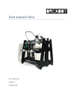
Ride Indexer 2010 Ride comfort analysis „Ride Indexer II“– Wz-value method according to Sperling User Manual (Software v2.5) Ride Indexer 2010 v2 — Ride comfort analysis Version 2.5 Table of contents I. II. III. IV. V. VI. General specifications .................................................................................................... 3 System requirements ...................................................................................................... 5 Installing the software .................................................................................................... 5 Uninstalling the software ............................................................................................... 7 Using the system ............................................................................................................ 7 Sensor characteristics ................................................................................................... 13 Page 2 of 13 Ride Indexer 2010 v2 — Ride comfort analysis Version 2.5 I. General specifications 1. Description of evaluation system: This software and hardware package offers a solution for data acquisition and evaluation according to following standards: ISO 2631-1 (2007-07-01), ISO 2631-4 (2001-02-01) and VDI 2057 (formulas for calculating k-value and maximum values). A sampling rate of 1 KHz (per channel) provides a satisfying ratio between accuracy and duration of online calculations. Evaluation of measured data, as stated on the test protocol: st o 1 line: rms-value of the evaluated acceleration Wb and Wd according ISO 2631-1 and -4 on the basis of the fundamental validation method with the rms-value of ISO 2631-1, point 6.1. o 2 line: Evaluation according ISO 2631-1 based on point C.2.3, rated from 1 to 6. Rate 1 complies with a vibration of less than 0.315m/s² and rate 6 equals a vibration of greater than 2.5m/s². According ISO 2631-1 borders between the single steps are overlapping. nd Overview of evaluation according ISO 2631-1: Classification according ISO 2631-1 Less than 0,315 m/s² 0,315 to 0,63 m/s² 0,5 to 1 m/s² 0,8 to 1,6 m/s² 1,25 to 2,5 m/s² Greater that 2 m/s² Classification of Ride Indexer 2010 Less than 0,315 m/s² Up to 0,63 m/s² Up to 1 m/s² Up to 1,6 m/s² Up to 2,5 m/s² Greater than 2,5 m/s² Classification 1 2 3 4 5 6 Reactions according ISO 2631-1 not uncomfortable a little uncomfortable fairly uncomfortable uncomfortable Very uncomfortable extremely uncomfortable rd o 3 line: Based on the results of the measured values of Wb and Wd and according to the german VDI-guidelines (VDI 2057) results are displayed as K-values. The used filter curves relate to the frequency weighting of ISO 2631. o 4 line: The maximum values are indicated as non-dimensional quantities based on the kvalues and correspond with the multiple of the sigma value (standard deviation) of the signals. The used filter curves relate to the frequency weighting of ISO 2631. o 5 line: Evaluation according Sperling’s Wz method is conducted by a band-pass filter with a frequency of 0.4 – 100Hz. For calculation Sperling’s formulas with root mean square values are used. th th Page 3 of 13 Ride Indexer 2010 v2 — Ride comfort analysis Version 2.5 Sperling’s ride evaluation scale: Ride quality Excellent Ride Index Wz 1,0 2,0 Good 2,5 3,0 Satisfactory 3,3 3,5 Operative 4,0 Not operative Dangerous 4,5 5,0 Vibration sensitivity slightly noticeable noticeable increasingly noticeable, but not unpleasant, tolerable strongly noticeable, turbulent, still tolerable strongly turbulent extremely turbulent, inconvenient , annoying, over a longer period of time intolerable extremely inconvenient, over a longer period of time - harmful — — 2. Sensor specifications The MEMS-technology used for this sensor (tri-axial sensor) allows for a high miniaturization of the device. The possibility of analysing vibrations on the 3 axles and their combinations allows for an elimination of interference with the help of a matrix based calibration database. Adjusted measuring data will be available immediately online for further processing. For an evaluation according Sperling’s method only two axles are necessary. For a full evaluation according ISO 2631-1 an evaluation on the 3 main axles is available on request. 3. Combination of PC’s + sensors Depending on individual orders multiple sensors with related calibration data can be used for each delivered software (optional with GPS module). Up to 4 sensors and one GPS mouse can be used at the same time at one PC. Fig.: Multiple installations Page 4 of 13 Ride Indexer 2010 v2 — Ride comfort analysis Version 2.5 II. System requirements Minimum hardware requirements: 1,2 GHz Processor 1 GB RAM Sufficient number of USB ports (for additional power supply) or USB-hub with external power supply Min. display resolution 1024 x 768 o o o o Minimum software requirements: Windows XP Service Pack 2 or higher 500 MB free disc space Microsoft Office – Excel (2003, 2007, 2010) o o o Note: A constant processor load of 100% could mean that system requirements are not enough or too many programs are running at the same time. III. Installing the software 1. To install the Ride Indexer 2010 — v2 software run the Setup file. Administrator rights are necessary. 2. The Ride Indexer 2010 v2 — Overallrun starts automatically. Fig.: Overallrun a. It includes the driver for the a-USB sensor that runs in a separate DOS-window (closes automatically after installation is completed). The a-USB-sensor will be detected automatically at initial connection. Note: If the installation of the a-USB driver does not start automatically it can be added manually. Just run the program CDM20802_Setup which you find in the folder Start Programs Ride Indexer 2010 v2 USB Sensor. The sensor needs to be disconnected during installation. If it does not work, the software can be installed via the normal Windows installation routine. Follow the Windows installation procedure. In the program folder …\Ride Indexer 2010 v2\Treiber\USB Treiber\CDM20802 WHQL Certified all files for a subsequent installation can be found. b. Next step is installing the GPS-software. Just follow the programs instructions. For manual installation go to Start Programs Ride Indexer 2010 v2 GPS Mouse Win2010 Note: After installation of the GPS-software a system restart may be required .Make sure installation routine has finished before restarting the system. Page 5 of 13 Ride Indexer 2010 v2 — Ride comfort analysis Version 2.5 3. Measured data is saved in TDMS-format. With a free Add-on of „National Instruments― measuring data can be opened and edited in Microsoft Excel. This Add-on is automatically included in the installation of the program. For manual installation go to Start Programs Ride Indexer 2010 v2 Excel Add-on. An additional activation in Microsoft Excel may be required – for detailed information go to Excel-Help. 4. Installation under WIN7 AND 64x-system (help when installing the sensors driver): Sensors may not be detected because WIN7 works with 2 different library folders (one for 32bit, one for 64bit applications). In that case please proceed as follows: Following files need to be copied to „…\windows\SysWOW64“: nsp.dll nspa6.dll nspm5.dll nspm6.dll nspp6.dll nsppx.dll nspw7.dll Page 6 of 13 Ride Indexer 2010 v2 — Ride comfort analysis Version 2.5 IV. Uninstalling the software 1. Uninstalling with Windows control panel For uninstalling the software go to Windows Control Panel → Software. You will find following entries: o Ride Indexer 2010 v2 o Software von National Instruments o VISA Shared Components o GPS driver Uninstalling is done via normal Windows procedure. 2. Manual uninstalling of „National Instruments“ and „FTDI driver“ o For manual uninstalling you find the file msiBlast.exe in the folder Ride Indexer 2010 v2.0. All software components of National Instruments can be removed with msiBlast. Extensive computer skills are required because a misapplication may result in deletion of all programs installed. o The driver of the a-USB-sensor can be uninstalled in the device manager under „COM and LTP connections‖ or ―USB-converter―. V. Using the system To start the program - go to: Start → Programs → Ride Indexer 2010 v2. Administrator rights are not necessary to use the program. 1. Connecting the sensors a. a-USB-sensor connection and initialization All a-USB-sensors that have been connected before starting the program will be detected automatically. This will take a few seconds. Additional sensors can be connected during operation. In Sensors → a-USB-sensor you can see the sensor database where all connected sensors are displayed. Sensors that include entries are enabled. This verification of the serial number ensures that corresponding calibration data is used. Sensors connected during program run can be registered by “Sensors reinitialise”. Page 7 of 13 Ride Indexer 2010 v2 — Ride comfort analysis Version 2.5 Fig.: Sensors database Note: The sensors power consumption in operation is 200mA. However, connecting the sensor may result in a current overload of the USB interface. This event has to be reset. To prevent a current overload Y-USB cables or USB hubs can be used because they allow for higher intensity of current. The window Acceleration (unfiltered values) shows whether the sensor offers data or not. Relative values in [m/s²] are displayed optionally including static gravity acceleration of the zaxis (only display). The y-axis’ (a) scaling can be changed by double-clicking it. Those changes will be retained when starting the program next time (settings will be saved at ini-file). b. GPS-mouse/sound To connect the GPS-mouse, the correct COM-port has to be selected. Which COM-port was chosen for the GPS by the operating system can be seen in the device manager. The according interface can be selected in sensors/GPS-mouse/sound. With menu item interval time the time intervals between time entries in the protocol can be set. In contrast to entries in the results data file were actualisation is always 1s. There you also find a slider to control the volume of the tone that signalises the end of a (part-) recording. Page 8 of 13 Ride Indexer 2010 v2 — Ride comfort analysis Version 2.5 2. Positioning of sensors The sensor consists of 4 magnetic fittings that guarantee a secure hold on iron plates (not included in delivery). Adjust the sensor on a plane surface of the vehicle with the connecting cable being transversely with respect to the direction of running (x-axis). Running direction (x-axis) Running direction (x-axis) Fig.: Axis orientation 3. Settings and menu o o By selecting menu item Protocol settings custom protocol settings can be made and these settings will be retained at the next program start. Following menu items are available for custom settings: Menu item Protocol settings offers the possibility to create a test protocol With menu item Results data TDMS all measured data will additionally be saved in an according file. These measured data includes unfiltered values (raw data) that were recorded with a sampling rate of 1 KHz. Note: A constant recording with 4 sensors + GPS over a period of 4 hours produces file sizes of 1GB. Such file sizes generally cause long waiting periods in Windows and often system crashes. See also Point 5. By selecting Auto filename generation a dialogue window opens at the end of every measuring for specifying individual name and file location. The file path is shown in the status field (j). A different file can be selected in menu item Change protocol standard folder. Data (Protocol/results data) is saved automatically in the subfolder „Date“. By selecting menu item Options changes can be specified. These changes will be retained at the next program start. Language changes will be effected only after a restart. Note: Settings will be stored in file ri.ini that can be found in folder Ride Indexer 2010 v2. If this file is deleted - default settings will be used. o The software can also be operated using key combinations (e.g. CTRL+a would be the a-USB-sensor for the menu bar, CTRL+e to end the program) and function keys: F1 = Help/Description F2 = start/end Single measurement F3 = choose Repeated measurements PageUp / PageDown = timer operation Page 9 of 13 Ride Indexer 2010 v2 — Ride comfort analysis Version 2.5 F4 = Focus on field for manual time setting F5 = Focus on field General information F6 = Focus on field User a b c d e f g h k i j 4. Measurement and recording: o During measuring all menu items are locked to ensure an uninterrupted measuring. o Recording can be started by pressing the “On” button (g) and it runs for the period of time that has been selected previously with the timer (b). Field Countdown(c) shows the remaining time until end of measuring. Recording will be completed ―nonstop‖. Ending is indicated by a signal tone, the sound volume can be adjusted in Options GPS/Sound. o In field d measuring time can be entered manually. Measuring periods from 00:00:04 to 23:59:59 are possible. When choosing measuring durations of more than 4 minutes (-0/+5) no protocol will be generated for reasons of processor performance. Results data will be saved if previously selected in protocol settings. Note: The signal data file always includes a longer recording time as selected by the timer. But for calculation only the selected period of time will be used. o Measurements can be stopped at any time by pressing „Stop―. o The status panel (e) shows protocol number, file format and counter. At single measurements the counter is always 1, at continuous measurements it indicates the consecutive number within the protocol. o With „Single―and „Duration“ (k) you can choose between single and continuous recordings (= time-linked single recordings). No data will be recorded during calculation of ride index and protocol creation. o Results are displayed in field Evaluation matrix (f). If previously selected in the protocol settings a test protocol / result data file will be generated immediately after Page 10 of 13 Ride Indexer 2010 v2 — Ride comfort analysis Version 2.5 recording finishes and saved in My documents/Ride Indexer 2010/”Date ―. A shortlink can be found in menu item Protocol file. Example: …/My Documents/Ride Indexer 2010 Protocol files/2010_03_11 There is a subfolder for each day measurements are carried out. Note regarding TDMS-format and Excel: Limitations concerning TDMS-files, which can be opened in Excel: At a recording time of 2 minutes 56000 rows will be created and therefore are readable with Excel 97-2003 ( maximum number of lines is 65536) Excel supports a maximum of 254 worksheets. If the TDM-file includes more, only the first 254 sheets will be imported. There are no limitations on „Protocol.xls“-files concerning amount of spreadsheets. Depending on recording time TDMS-files may be too large to be processed in Excel. Maximum Limit Excel 2007 Excel 97-2003 Columns 16’384 256 Rows 1’048’576 65’536 Sort key 64 3 Colours 4’294’967’296 56 Unique cell formats/cell styles 65’536 approx. 4’000 Nested levels of functions 64 7 Length of formula contents 8’192 1’024 Arguments in a function 255 30 Filter drop-down lists 10’000 1’000 Table: Limitations in Excel Microsoft Excel 2003 is limited to 1 GB of memory. Microsoft Excel 2007 has no limitations and is only limited by available memory and system resources. o Comments can be added before measuring is finished in the field General information (h). These comments will be included in the test protocol as well as the operator’s name that has to be entered into field User (i). Note: Settings like recording time, comments and name of test operator are stored in the file ri.ini. and will be available at the next program run. o Protocols in xls-format Depending on the amount of sensors up to 4 row groups will be issued. At continuous measurements multiple sheets will be created per recording. Page 11 of 13 Ride Indexer 2010 v2 — Ride comfort analysis Version 2.5 Fig.: Sample test report o Protocol in pdf-format Additionally, protocols will also be stored in pdf-format. One page will be created per recording. e.g. at a continuous measuring with 3 single recordings 3 pdf-pages will be created. The consecutive sheet numbers are included in the file name. Protocol 1_sheet_1.pdf Protocol 1_sheet_2.pdf Protocol 1_sheet_3.pdf 5. Program crash All recorded data is stored in the relative folder „…\Local settings\Temp―. Files that start with „Protocol…― are generated by Ride Indexer 2010 and remain there in case of a program crash. At a restart of RI 2010 all referring files will be overwritten. Also, sensors have to be reconnected after a system crash. 6. Disconnecting a sensor from USB-port during recording If sensors are disconnected during a recording, data recorded until then will be analysed. If no values are available or the recording time was smaller then 10ms ―NaN‖ (Not a Number) will be displayed in the protocol. It is advisable to re-initialise remaining sensors after finishing a recording. Page 12 of 13 Ride Indexer 2010 v2 — Ride comfort analysis VI. Sensor characteristics Triaxial sensor Final value Bandwidth Resolution Ground noise Dimensions Weight Cable length Fitting Communication Power consumption in operation Protection class Shock resistance Temperature CEI UNI CEI UNI +/- 5g 0 - 2,5kHz 0,0025m/s² 0,075m/s² 30 x 55,5 x 15mm 55g 3m (extension to 30m) magnetic USB 2.0 200mA IP67 10.000g 0 - 70°C EN 61000-6-2 EN 61000-6-4 Fig: Dimensions Page 13 of 13 Version 2.5