1
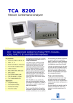
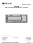
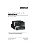
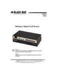
DECEMBER 2006
ME231A
ME232A
ME233A
G.SHDSL NTU
with Fixed Serial Interfaces
CUSTOMER Order toll-free in the U.S. 24 hours, 7 A.M. Monday to midnight Friday: 877-877-BBOX
SUPPORT FREE technical support, 24 hours a day, 7 days a week: Call 724-746-5500 or fax 724-746-0746
INFORMATION Mail order: Black Box Corporation, 1000 Park Drive, Lawrence, PA 15055-1018
Web site: www.blackbox.com • E-mail: [email protected]
G.SHDSL NTU
• The G.SHDSL NTU contains no user serviceable parts. The
equipment shall be returned to Black Box for repairs, or
repaired by qualified service personnel.
WARNING
• The external power adaptor shall be a listed limited
power source that incorporates a disconnect device and
shall be positioned within easy reach of the operator. The
mains outlet shall be within 10 feet (3 meters) of the
device, shall be easily accessible, and protected by a circuit breaker.
• For AC powered units, ensure that the power cable used
meets all applicable standards for the country in which it
is to be installed, and that it is connected to a wall outlet
which has earth ground.
• Hazardous network voltages are present in WAN ports,
regardless of whether power to the G.SHDSL NTU is ON
or OFF. To avoid electric shock, use caution when near
WAN ports. When detaching the cables, detach the end
away from the G.SHDSL NTU first.
• Do not work on the system or connect or disconnect cables
during periods of lightning activity.
• For DC units, the interconnecting cables shall be rated for
the proper voltage, current, anticipated temperature,
flammability, and mechanical serviceability
TRADEMARKS USED IN THIS MANUAL
All applied-for and registered trademarks are the property of their respective owners.
2
G.SHDSL NTU
1. Select configuration method
Before powering up, you must select one of the following methods for configuring your G.SHDSL NTU:
• DIP Switch—For deploying the G.SHDSL NTU in back-to-back applications.
To use DIP-switch configuration you must first set the DIP switches to a position other than all OFF or all ON before powering-up the G.SHDSL NTU. To
configure your NTU using the DIP switches, refer to the section entitled
“Hardware (DIP-switch) configuration” in the G.SHDSL NTU Getting Started
Guide.
• Software Configuration—Allows you to modify configurable parameters by
connecting a PC to the console port and issuing software commands. To use
software configuration you must set all the DIP switches to the ON position
before powering-up the G.SHDSL NTU. To configure your NTU via the console port, refer to section “Software (CLI) configuration” in the G.SHDSL NTU
Getting Started Guide.
3
G.SHDSL NTU
2. Power up the NTU
Your G.SHDSL NTU comes with one of the following power supply options:
• External AC adaptor with detachable power cord
• External DC power supply with terminal block connector (model 48V-PSM)
2.1 Models with external AC adaptor
1. Connect female plug of the AC power cord to the AC adaptor provided.
2. Connect the barrel-type connector of the AC adaptor to the Power connector on the G.SHDSL NTU.
3. Insert the male plug of the AC power cord into an AC power outlet (100–
240 VAC).
2.2 Models with external DC power supply
1. Strip insulation 1/4-inch from the electrical wires that will connect the DC
power source to the 48VDC power supply terminal block (see Figure 1).
we
r
le Su
ut:
36–
( 60
V
S
D
E
N/C LV) C, 0.
13A
-)
Po
(+
Inp
In
pu
t:
3A
.1
,0
C
D
0V ) )
–6 LV 36 (SE /C
N
ly
pp
Su
er
w e
+)
Po ul
tr
C od
(C
D M
V
A
48
,1
5V
ut:
utp
O
(+
Terminal
block
(-) Terminal
(+) Terminal
Figure 1. 48VDC power supply
2. Connect the negative (-) terminal from the power source to the negative (-)
terminal on the power supply.
3. Connect the positive (+) terminal from the power source to the positive (+)
terminal on the power supply
4. Connect the 48VDC output barrel-type plug to the power connector on the
G.SHDSL NTU.
4
G.SHDSL NTU
U
NT
Console
TM / ERR
Terminal
DSL
Power
Figure 2. G.SHDSL NTU front panel
2.3 Power up indication
Verify that the Power LED (see Figure 2) illuminates and remains lit.
5
G.SHDSL NTU
3. Connect the G.SHDSL port
1. Obtain single-twisted-pair cable with an RJ-45 plug connector at each end.
2. Plug one end of the cable into the RJ-45 socket (labelled DSL) on the
G.SHDSL NTU.
— If you are connecting to a DSL service, plug the other end of the
cable into the RJ-45 wall socket that provides your G.SHDSL service.
— If connecting to another G.SHDSL NTU, verify the other end of the
cable is connected to the DSL port on other G.SHDSL NTU and the
DSL port is correctly configured.
3. When a DSL link is established, the front-panel DSL LED will turn on.
6
G.SHDSL NTU
4. Connect the serial port
Your G.SHDSL NTU comes with one of the following serial WAN ports for connection to an NTU:
• V.35 (DB-25F)—Model ME233A
• X.21 (DB-15)—Model ME232A
• T1/E1 (120-Ohm RJ-48C and dual 75-Ohm BNC connectors)—Model
ME231A
Connect the serial cable to the G.SHDSL NTU serial port as follows:
1. Attach the male connector of the serial cable to the female serial connector
on the G.SHDSL NTU.
2. Attach the other end of the cable to the serial connector on the local serial
NTU.
Note
The V.35 interface is wired as a DCE. To connect the V.35 interface to
third-party equipment wired as a DCE, you must use a tail-circuit cable.
You can purchase a tail-circuit cable from a datacom-supply vendor. A
tail-circuit cable will cross-over the necessary V.35 signals so that the
two DCE interfaces can communicate.
Note
The X.21 interface is wired as a DCE. If you need to change the orientation to DTE, refer to section “Connecting the Model ME232A (X.21)
Serial Interface” in the G.SHDSL NTU Series Getting Started
Guide, The X.21 interface requires a cable with a male DB-15 connector.
Note
You can configure the T1/E1 interface to either recover the network
clock from the T1/E1 line or supply the network clock for the T1/E1 line.
7
G.SHDSL NTU
5. Additional information
For detailed information about installing, configuring, operating, and troubleshooting, refer to the G.SHDSL NTU Series Getting Started Guide on the
enclosed CD-ROM.
A. Compliance Information
A.1 Compliance
EMC:
• FCC Part 15, Class A
• EN55022, Class A
• EN55024
Safety:
• UL 60950/CSA C22.2 N0. 60950
• IEC/EN60950
PSTN Regulatory:
• FCC Part 68
• CS03
• TBR12, & TBR13
• AS/ACIF S031 & S043
A.2 FCC Part 68 (ACTA) Statement
This equipment complies with Part 68 of FCC rules and the requirements adopted
by ACTA. On the bottom side of this equipment is a label that contains—among
other information—a product identifier in the format US: AAAEQ##TXXXX. If
requested, this number must be provided to the telephone company.
The method used to connect this equipment to the premises wiring and telephone
network must comply with the applicable FCC Part 68 rules and requirements
adopted by the ACTA.
8
G.SHDSL NTU
If this equipment causes harm to the telephone network, the telephone company
will notify you in advance that temporary discontinuance of service may be
required. But if advance notice isn’t practical, the telephone company will notify
the customer as soon as possible. Also, you will be advised of your right to file a
complaint with the FCC if you believe it is necessary.
The telephone company may make changes in its facilities, equipment, operations or procedures that could affect the operation of the equipment. If this happens the telephone company will provide advance notice in order for you to make
necessary modifications to maintain uninterrupted service.
If trouble is experienced with this equipment, for repair or warranty information,
please contact our company. If the equipment is causing harm to the telephone
network, the telephone company may request that you disconnect the equipment
until the problem is resolved.
Connection to party line service is subject to state tariffs. Contact the state public
utility commission, public service commission or corporation commission for
information.
5.4 Radio and TV Interference (FCC Part 15)
This equipment generates and uses radio frequency energy, and if not installed
and used properly—that is, in strict accordance with the manufacturer's instructions—may cause interference to radio and television reception. This equipment
has been tested and found to comply with the limits for a Class A computing
device in accordance with the specifications in Subpart B of Part 15 of FCC rules,
which are designed to provide reasonable protection from such interference in a
commercial installation. However, there is no guarantee that interference will not
occur in a particular installation. If the equipment causes interference to radio or
television reception, which can be determined by disconnecting the cables, try to
correct the interference by one or more of the following measures: moving the
computing equipment away from the receiver, re-orienting the receiving antenna,
and/or plugging the receiving equipment into a different AC outlet (such that the
computing equipment and receiver are on different branches).
5.5 Industry Canada Notice
This equipment meets the applicable Industry Canada Terminal Equipment Technical Specifications. This is confirmed by the registration number. The abbreviation, IC, before the registration number signifies that registration was performed
based on a Declaration of Conformity indicating that Industry Canada technical
specifications were met. It does not imply that Industry Canada approved the
equipment.
9
G.SHDSL NTU
This Declaration of Conformity means that the equipment meets certain telecommunications network protective, operational and safety requirements. The
Department does not guarantee the equipment will operate to the user's satisfaction. Before installing this equipment, users should ensure that it is permissible to
be connected to the facilities of the local telecommunications company. The
equipment must also be installed using an acceptable method of connection. In
some cases, the company’s inside wiring associated with a single line individual
service may be extended by means of a certified connector assembly (telephone
extension cord). The customer should be aware that compliance with the above
condition may not prevent degradation of service in some situations. Repairs to
some certified equipment should be made by an authorized maintenance facility
designated by the supplier. Any repairs or alterations made by the user to this
equipment, or equipment malfunctions, may give the telecommunications company cause to request the user to disconnect the equipment. Users should ensure
for their own protection that the ground connections of the power utility, telephone lines and internal metallic water pipe system, are connected together. This
protection may be particularly important in rural areas.
5.6 EC Declaration of Conformity
Product Description: G.SHDSL NTU with Fixed Serial Interfaces
This equipment conforms to the requirements of Council Directive 1999/5/EC on
the approximation of the laws of the member states relating to Radio and Telecommunication Terminal Equipment and the mutual recognition of their conformity.
The safety advice in the documentation accompanying the products shall be obeyed.
The conformity to the above directive is indicated by the CE sign on the device.
In accordance with the requirements of council directive 2002/96/EC on Waste of
Electrical and Electronic Equipment (WEEE), ensure that at end-of-life you separate
this product from other waste and scrap and deliver to the WEEE collection system in
your country for recycling.
10
G.SHDSL NTU
11
© Copyright 2006. Black Box Corporation. All rights reserved.
1000 Park Drive
•
Lawrence, PA 15055-1018
•
724-746-5500
•
Fax 724-746-0746