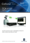
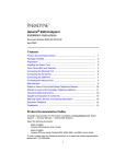
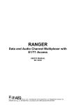
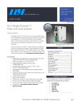
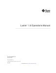
1
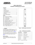
TCA 8200
Telecom Conformance Analyzer
One – box approvals solution for Analog PSTN, Acoustic,
xDSL, VoIP, T1, E1 and ISDN PRI interfaces
Key standards
•
TS103 021, TBR 21, EG 201 121
•
TBR 4, 12, 13
•
EN 301 437,TBR 37, 38 (Europe)
•
FCC Part 68, TIA-968-A (USA)
•
CS-03 (Canada)
•
S002, S003, S004, S016 (Aus)
•
JATE (Japan)
•
ITU-T G.703, G.823, G.824
•
ETSI TS 102 027-1, 2 (SIP)
•
ITU-T P.862 (PESQ VQT)
Applications
•
Compliance testing
•
Pre-compliance testing
•
Development testing
•
Production testing
TCA 8200
Compliance testing to world’s
major standards
TCA 8200 provides compliance testing
solution according to the world’s major
network access standards, covering
many types of telecom equipment ranging from handset telephones to digital
switches, PBXs and VoIP gateways. In
the past, approval of terminal equipment
meant using a test lab with expert test
engineers and tens of non-automated or
semi-automated expensive test instruments and setups. Such process usually
took weeks.
With TCA 8200 you can complete the
tests and the documentation required by
the standards and agencies in a matter of
hours without a need for in-depth knowledge of the standards.
Due to recent liberalization of regulation
processes in Europe, the USA and other
countries manufacturers can now perform
in-house testing and declare compliance
or apply for approval of a regulatory
agency. Having an in-house compliance
testing solution from early design stages
can significantly reduce time-to-market.
Test labs can benefit also from the ability
to provide fast and cost-effective testing
services for a broad range of the interfaces and standards covered by the instrument, its expandability and its extensive management features.
Fully automated testing
TCA 8200 comes with test suites ready
for testing according to the supported
standards. The tests can be performed in
a fully automatic manner one by one or in
a sequence.
No user interaction is required except for
setting of the equipment under test in
response to prompts appearing on the
screen.
1
HERMON LABORATORIES
Test project
Test run
Test report
Completely unattended testing is
possible for equipment that can be
remotely controlled with ASCII
commands.
Any user-defined commands or built-in
AT commands can be used for automatic remote control of the equipment
over RS-232 or TCP/IP Ethernet.
Such functionality together with the
capability to define custom tests and
test sequences is especially useful for
production testing.
Reports in MS Word format with test
results and all the information required
for a test project are generated automatically.
Deciding what standard’s tests are
applicable for a particular product can
be sometimes a complicated task.
Predefined and user-defined criteria
for selection of the required tests
simplify this task. The tests are automatically selected by answering Yes/
No questions about the functionality
supported by the product.
The tests can also be selected manually.
A test can be automatically repeated
with different (or the same) sets of test
parameters and limits.
TCA 8200
Powerful Display and
Analysis features
Test results are displayed continuously
on graphs and table, together with
current test status and verdict, key test
parameters, user prompts, current test
point and measured values.
Time and frequency domain measurements with minimum, maximum and
average statistics are provided.
In each test, you can set which results
will appear on the display and in the
test report, set limits, number of plots
per graph, style and color of each plot,
select Log or Linear axis, set axis
scale or select auto-scaling, select
which test parameters will appear in
the test report, rename test results,
add comments and environment
conditions description to test results.
Measured results can be analyzed by
using markers, delta markers, zoom in/
out, max/min peak search, scroll and
pan graph features. Further analysis is
possible by copy/pasting the results to
the preinstalled MS Excel.
Manual operation
Besides fully automated testing
capability, TCA 8200 provides onthe-fly control of test parameters,
“manual” tuning and stepping, which
is important for development and
debugging testing. Test execution
can be paused/resumed, automatically swept or manually stepped
through multiple test ranges. Also a
test can be run once or continuously,
at multiple test points or at a single
test point (e.g. frequency).
2
1. Setting results format
Lab in a box
TCA 8200 is not just a test instrument. It is also a highly integrated system of
tools and features for performing and supporting tasks required in a test lab
such as:
•
Definition and management of test specs and test plans with customized user prompts, remote EUT control commands, and automatic tests
selection criteria.
•
Running and management of test projects.
•
Integral client information database linked to test projects.
•
Generation and management of test reports.
•
Built-in calibration tests.
•
Backup and restore of all data and restore of the factory data.
•
Emergency recovery of all software and factory data from image disk
supplied with the system.
•
Quality assurance issues have been thoroughly addressed: Test reports
are ISO/IEC 17025 compatible. Tests, test suites, projects, reports are
uniquely identified. Changes to test definitions are recorded.
2. Setting limits
Versatility and ease of use
TCA 8200 features familiar Windows user interface.
Test suites, test projects, tests, reports and other data and tools are presented in Windows Explorer-like tree/list views.
Intuitive Open, New, Delete, Save, Properties data operations are implemented through double-click, menus, toolbar icons, and right mouse button
context-sensitive pop-up menus.
3. Setting test ranges
In addition to built-in tests, users can easily create new custom tests by setting results format, test parameters, ranges, limits, EUT remote control commands, user prompts and test execution sequence. No programming or
scripting is required. Both system and user tests are grouped in test suites.
New test suites for new standards or for user specifications can be created.
Test suites are used to access, set and run tests, and serve as templates for
new suites and projects.
Project provides tools to run and manage tests, store and document test
results. Project is created from one or multiple test suites, inheriting all their
definitions.
It contains all the information required for a test project:
•
Details of the product under test.
Client details.
Project performance information.
•
Test specification - group of tests with test definition, created from one
or more test suites. You can modify the test specification in the project.
You can also save the project test specification as a test suite, so it can
be used as a template in other projects and suites.
•
•
Project and tests status and verdict.
4. Setting test parameters
Test results are saved for each test execution in the project. You can
select which results will be included in the test report. You can generate
test reports in MS Word format for each test suite included in the project. You can open, print and delete test reports from the project. You
can include MS Word documents in a test suite or in a project to document unsupported tests or to include additional information in a test
report.
TCA 8200
3
On-line help and support
TCA 8200 features a
comprehensive context-sensitive online help with examples and step-bystep guidance.
The tests are thoroughly documented with EUT connection and
configuration instructions, test
specification and measurement
uncertainty data.
The TCA 8200 user interface accommodates both novice and advanced user’s needs. Step-by-step
wizards are provided together with
straightforward shortcut operations.
Remote configuration, user guidance and training can be provided
over internet through remote operation of the TCA 8200.
Interoperability
TCA 8200 includes all common PC
interfaces: USB, parallel, RS-232
and Ethernet, which allows test
reports and results printing to any
Windows compatible local or
network printer.
Test reports and backups can be
stored on the internal hard disk,
external or network drive.
TCA 8200 can be transparently
operated from a remote PC over
LAN and internet by using the Windows Remote Assistance feature.
Low cost of ownership
TCA 8200 comes with a price
significantly lower than the total cost
of equipment and systems it can
replace such as a digital
oscilloscope, spectrum and network
analyzers, digital transmission and
jitter analyzer, line and cable
simulators, power supplies, protocol,
frame, signaling analyzers, various
test bridges and a PC. Achieving
automation requires further investment in integration and software
development or buying expensive
third-party solutions.
be upgraded later for any additional
options.
Testing capabilities can be easily
extended to cover new standards by
defining new user test suites using
the GUI or obtaining updates from
Hermon Laboratories.
Analog PSTN interface
testing
The Analog PSTN tests cover the
requirements for terminal (CE) and
network (CO) equipment including
electrical AC, DC and timing characteristics in on-hook, off-hook states
and during the transition between
those states, various functional and
simulation tests.
CO, CE, and line simulation
Extensive analog PSTN network
simulation features found in standalone line simulators coupled with
line states and dialed number
recording provide an invaluable tool
for functional tests.
Different CO’s and networks can be
simulated by predefined and userset call progress scenarios with
programmable conditions, valid/
invalid numbers definition, delays,
dialing timeouts, connection to second auxiliary channel, progress
tones and ring signals.
A database of predefined progress
tones and ring signals used in different countries is provided.
Acoustic testing
Acoustic tests are required to verify
that speech performance of handset
telephones is adequate to ensure
compatibility with the PSTN and
other telephones. The speech
performance is assessed by
measuring transmission
characteristics at various
combinations of transmission paths:
Sound pressure is applied to the
telephone handset microphone and
measured at the speaker.
Stimulus signals are applied and
measurements are performed at the
telephone line interface with various
loop simulation characteristics.
The handset is placed in a test head
which provides the reference
standard positions from the built-in
ear and mouth simulators.
The ear and mouth simulators are
connected to the TCA 8200 via input
preamplifier and output power
amplifier.
The receiving and sending sensitivity, noise, distortion, loudness,
linearity, instability, echo return loss
and side tone tests are performed
according to procedures and
specifications defined in ITU-T P.64,
P.79 and ETSI TBR 38.
Digital T1 and E1
interfaces testing
The digital tests cover layer 1 electrical characteristics of input and
output ports, digital, combined analog and digital transmission and
functional characteristics of framed
and unframed T1 and E1 interfaces.
In addition to test results shown on
graphs and table, line monitor indicators display current error and
alarm status of the TCA T1 or E1
receiver.
Acoustic Test Setup
Due to the instrument’s modular
design you can order and pay for
the test options that you need. You
can order separately Analog PSTN,
E1, T1, Analog PSTN + DSL, Analog PSTN + Acoustics or E1 + ISDN
PRI test options. The instrument can
TCA 8200
4
Jitter measurement tests feature amplitude auto-ranging and display of
the measured jitter modulation waveform versus time.
Pulse shape tests provide simultaneous measurements of all positive and
negative pulses, and space characteristics with automatic mask fittings
and scaling, and user-defined masks.
Frame analysis tests provide the most
powerful features for simulation and
analysis of 2.048 Mbps CCS & CRC
structure.
In the heart of the frame analysis
tests lies the Test Procedure definition which contains a sequence of
Pulse Shape measurement
test cases.
Each test case includes a userdefined transmit data pattern of variable length and the expected receive
events criteria. Predefined error,
alarm or data patterns are provided.
You can also set any bit in framing
and each data timeslot.
You can define a series of expected
receive events such as CRC error,
frame error, RAI, FEBE and AIS conditions with start time, duration repetitions limits for each event.
When a frame analysis test is run the
test cases sequence is executed. The
data patterns are transmitted; the
received events are recorded with
single frame resolution and compared
to the expected events criteria with
automatic verdict setting.
Predefined frame analysis tests such
as TBR 4 9.4 Frame structure and 9.5
Operational functions tests are provided.
CAS simulation and analysis coupled
with built-in database of signals and
signaling states provide powerful testing capability of virtually any E1/T1
CAS protocol.
The L23 option provides full layer 2
and 3 testing of 2.048 Mbps ISDN
PRI in accordance with TBR 4.
The tests include a user-defined series
of TTCN test cases defined in TBR 4.
TTCN is a programming–like language
that describes protocol simulation,
analysis, and verdict criteria test procedure.
When the layer 2 or 3 tests are run the
test cases are executed one-by-one
with automatically-set verdicts and
recording of transmit and receive
layer 2, 3 messages.
Frame Analysis test case definition
Jitter measurement
TCA 8200
5
2.048 Mbps interface (opt. E1)
Specifications
Supported standards1,6
Analog PSTN 2 / 4-wire TE and CO
(opt. ALG)
ETSI TS 103 021, TBR 21, EG 201 121 (Europe)
2
FCC Part 68 , TIA-968-A (USA)
CS-03 Part I (Canada)
AS/ACIF S002, S003 (Australia)
JATE, Analog Terminals (Japan)
IDA TS PSTN 1 (Singapore)
HKTA 2011, 2013 (Hong Kong)
MoC 023/96 (Israel)
Decree No. 322 (Brazil)
ITU-T O.9, O.81, G.712, Q.551, Q.552, Q.553
2
3
4
5
FCC Part 68, TIA-968-A (USA) (ADSL)
T1.TRQ.6-2001 (USA xDSL)
CS-03 Part VIII (Canada xDSL)
AS/ACIF S043.2 (Australia xDSL)
4
ETSI TS 101 388 (ADSL)
ITU G.991.2 (SHDSL)
4
4
4
ETSI TS 101 270-1 1 (VDSL)
4
1.544 Mbps interface (opt. T1)
FCC Part 68, TIA-968-A (USA)
CS-03, Part II (Canada)
JATE, Digital Terminals (Japan)
HKTA 2017, 2018, 2028 (Hong Kong)
ITU-T G.703, G.704
ITU-T G.824
ITU-T O.9, O.81, G.712, Q.551, Q.552, Q.553
TCA 8200
- Excluding: Magnetic field HAC test
- opt. L23 is required for Layer 2 and 3 testing
- See xDSL electrical characteristics and transmit power below, for
6
- Requires third-party base station transceiver equipment
- Contact Hermon Laboratories for other available standards
Main tests
Analog PSTN
xDSL: ADSL, HDSL, HDSL2, HDSL4,
SHDSL, SDSL, VDSL CPE and CO
(opt. DSL)
ITU-T G.992.2 (G.LITE ADSL)
- Excluding: High voltage (surges, overvoltage protection, leakage current),
EMC, safety, environmental tests
supported tests
5
EN 301 437 (former TBR 37) , TBR-38 (Europe)
FCC Part 68
AS/ACIF S004 (Australia)
ITU-T P.340, P.313
TIA/EIA – 470
ITU-T G.992.1 (ADSL)
3
ISDN PRI: TBR 4 (Europe) – Layers 1, 2, 3
AS/ACIF S003, S016 (Australia)
JATE, Digital Terminals (Japan)
NOM – 152 (Mexico)
ITU-T G.703, G.704
ITU-T G.823
ITU-T O.9, O.81, G.712, Q.551, Q.552, Q.553
1
Acoustics and Telephonometry testing of
handset and hands-free telephones
(opt. ACU)
ETSI/3GPP TS 151 010-1 (Digital cellular phones)
TBR 12 (Europe)
TBR 13 (Europe)
Automatic dialing
Automatically repeated call attempts
Clearing of automatic calls
DC characteristics in on-hook and off-hook states: Voltage vs current,
resistance vs current, DC current
DC Resistance
DTMF, MF, MFC Signaling
Received digits, digit waveform vs time / frequency, low & high group
voltage / power / frequency, twist, tone / pause / cycle duration with
statistics, noise, rise & fall time
DTMF, MF, MFC digits generation with programmable frequency,
level and duration
Hazardous voltage limitations
Impedance in on-hook and off-hook states
Impedance - IZI, Phase, Resistance, Reactance, Inductance,
Capacitance, Return loss
Impulse noise
Insertion loss (Series TE)
Intentional operational paths to ground
Intentional protective paths to ground
Line liberation through power failure
Longitudinal conversion loss
Loop current characteristics
Loop interruption tolerance
Output signal balance
Progress tone detection and generation with programmable level,
frequency, duration, cadence and timing
Pulse signaling
Received digits, voltage/current vs time and voltage vs current plots,
make/break levels and duration, resistance, inter-digit pause, pulse
ratio – statistics
Pulse digits generation with programmable duration and N / N+1
encoding
Relative frequency response
R.E.N determination
Return loss
Ring detection and generation with programmable level, frequency,
duration, cadence and timing
6
Ringing impedance
Ringing signal overload
Series DC Resistance (Series TE)
Signaling interference
Spectrum Analysis
Signal and Noise level measurements vs time and frequency
Instantaneous, mean, RMS voltage and power – broadband and
narrowband with various BW and filters, psophometric noise,
impulsive noise - statistics
TIMS and Through Transmission – Narrowband and Broadband tests
(see 1.544 Mbps and 2.048 Mbps TIMS and PCM tests)
Through Transmission – SF cuttoff
Transient after change to the opposite polarity
Transient response
Transmission delay
Line, CO and TE simulation
Variable DC loop feed voltage and current limit
Variable series resistance, complex line length and terminations
Call simulation and analysis of FXS, FXO loop-start, DID and ground-start
interfaces including:
Generation, detection and measurements of
DTMF, MF, MFC signals and numbers with variable levels,
frequency, duration and timing
Pulse signaling with variable duration and N / N+1 encoding
Progress tones (dial, progress, busy, ringing tones, etc) and
Rings with variable level, frequency, cadence and timing
Off-hook, on-hook, wink, flash, polarity reversal and ground-start
states with variable characteristics
Playback and recording of .wav files
Programmable received event masks and if / then / goto conditions for
flow control of the simulation execution and verdict setting
Programmable user messages, user verdicts and remote commands
(for EUT automatic operation)
Pre-defined and user defined database of signals and encodings
Acoustics and Telephonometry
Acoustic shock
Receive Loudness Rating (ROLR, RLR)
Receive Volume Control and Hearing Aid Compatibility
Sending and Receiving Sensitivity frequency response
Sending and Receiving Sensitivity
Sending and Receiving Loudness
Sending and Receiving Linearity
Sending and Receiving Distortion
Sending and Receiving Noise
Sidetone and STMR
Spectrum analysis with acoustic stimulus
Sound Pressure Level (SPL) and SPL volume units
Instability and Howling
Echo return loss
xDSL electrical characteristics and
transmit power
Power spectral density
Aggregate total signal power
Spectrum Analysis
Longitudinal output voltage
Transverse balance
Longitudinal conversion loss
Return loss
Intentional operational paths to ground
Intentional protective paths to ground
On-hook resistance
TCA 8200
DC current during ringing
Ringing frequency impedance
1.544 Mbps and 2.048 Mbps interfaces
Layer 1 (Physical layer)
Clock accuracy measurements
Return loss
Transverse balance
Impedance towards ground
Tolerable longitudinal voltage
Receiver sensitivity
Bit Error Rate tests (BERT)
Pattern, line code, frame error and error rate; CRC error (2.048
Mbps), errored superframes (1.544 Mbps) RAI and REBE alarm
measurements (2.048 Mbps); LOS, LOF, AIS detection; pattern and
line code error insertion.
Immunity to attenuation and reflections
Simulation
Transmitter carrier level attenuation
Cable simulator attenuation
Interfering signal with 18 dB attenuation mixed with the
carrier
Error and alarm measurements
3.3V / 2.7V
0 / 6 / 12 dB
on/off
As in BERT
Jitter
Jitter generation and measurement, jitter transfer, jitter tolerance,
maximum tolerable jitter, wander generation complying or exceeding
O.171, G.823, TBR 4, 12, 13
• Jitter measurement and generation on data and clock
• Jitter Measurements:
UIpp and UIrms jitter level with statistics
Demodulated jitter vs time waveform
Low-pass and high-pass filters with continuously variable cutoff
frequency
• Error and alarm measurements
• Transmitter clock frequency offset
Pulse shape
Simultaneous positive, negative pulses and space measurements
with automatic mask fitting, with pulse width and pulse amplitude ratio
measurements with averaging and statistics. User-defined masks.
Output power and voltage
With time, spectrum and harmonic analysis
TIMS and PCM analysis
Two-channel A-A, A-D, D-A, D-D narrowband and broadband through
transmission tests
Stimulus/Measurement channels:
• (A) Analog channel A/B with DC loop feed simulation (in/out/off) –
opt. ALG required
• (D) Encoded/decoded into any PCM timeslot of 2.048 Mbps or
1.544 Mbps interface Tx/Rx port.
TIMS and PCM analysis tests include:
Gain, Loss, Level, Variation of gain with frequency, Variation of gain
with level, Idle channel noise, Crosstalk, Harmonic distortion, THD,
Intermodulation distortion, SINAD, SNR, Noise, Spurious (in-band and
out-of-band), Group delay, LCTL, TCTL, TBRL, SF cutoff, SF guard
band.
Frame analysis
Simulation and analysis of any error, alarm and normal operation
events of 2.048 Mbps CCS & CRC structure.
Simulation:
TBR 4 defined or user-set stimuli with up to single bit resolution,
inserted into any transmit framing and data timeslots.
Analysis:
Automatic verdict setting according to programmable expected events
criteria with time limits.
7
Event recording with time, frame and multi-frame stamp, and single
frame resolution.
CAS Signaling analysis
Call simulation and analysis of various CAS protocols:
ABCD bits signaling simulation and analysis
Encoded DTMF, MF, MFC signals and numbers with variable
levels, frequency, duration and timing
Encoded progress tones (dial, progress, busy, ringing tones, etc)
and
Rings with variable level, frequency, cadence and timing
Off-hook, on-hook, wink, and other states with variable
characteristics
Playback and recording of .wav files
Programmable received event masks and if / then / goto conditions for
flow control of the simulation execution and verdict setting
Programmable user messages, user verdicts and remote commands
(for EUT automatic operation)
Pre-defined and user defined database of signals and encodings
Layer 2 and 3 protocol analysis for
2.048 Mbps ISDN PRI
Layer 2 and Layer 3 TTCN conformance testing according to TBR 4
standard for 2.048 Mbps ISDN PRI with user-set PICS/PIXIT parameters
and recording of Tx and Rx layer 2, 3 messages in text and binary format
Voice Quality Testing (opt. VQT)
PESQ (Perceptual Evaluation of Speech Quality) through transmission
testing of a combination of the following TCA transmit – receive ports:
analog (FXS or FXO), acoustic (mouth or ear simulator), 2.048 Mbps
(A-law encoded in a payload timeslot), 1.544 Mbps (u-law encoded in
a timeslot) with on-line analysis and recording to . wav file(s)
Off-line analysis of degraded vs reference .wav files
Including the following measurements:
PESQ MOS per ITU-T P.862 and MOS LQO per ITU-T P.862.1
Delay and delay jitter
Reference and degraded signal level and loudness with aligned and
non-aligned waveforms
R factor (ITU-T G.107 e-model)
VAD (Voice Activity Detection) performance analysis:
Front End Clipping, Hold Over Time (Hang Over Time)
Speech dropout
Test Interfaces (front panel)
1544 kbits/s interface (opt. T1)
Tx and Rx connectors
3-pole Bantam jack, 100 Ω,
balanced
Line Coding
Framing Format
B8ZS, AMI
ESF (193E), D4 (193S),
Unframed
Clock Input / Output (opt. E1 or T1)
Input / Output 1.544 MHz or 2.048 MHz TTL signal, depending on test
configuration
Connectors
BNC female, unbalanced
2048 kbits/s interface (opt. E1)
Tx and Rx connectors
3–pin Siemens jack, 120 Ω,
balanced
BNC female, 75 Ω, unbalanced
Line Coding
Framing Format
HDB3, AMI
CCS & CRC4, CAS & CRC4,
CCS, CAS, Unframed
ISDN PRI Layer 2 and Layer 3
testing according to
ETSI TBR 4 (opt. L23)
Protocol Testing
SIP protocol conformance testing (opt. SIP)
Conformance testing of SIP - Session Initiation Protocol (defined in RFC
3261) over 10 / 100 Base-T ethernet interface per ETSI TS 102 027-1
V1.1.1 (2002-08), ETSI TS 102 027-2 V2.1.1 (2003-10)
SMS and CID testing (opt. SMS)
SMS and CID protocol testing over analog interfaces per
ETSI EN 300 659-1 V1.3.1, ETSI EN 300 659-2 V1.3.1,
ETSI EN 300 659-3 V1.3.1, ETSI ES 201 912 V1.1.1
ETS 300 648, ETSI EN 300 778-1,2 V1.2.1
TCA 8200
8
Analog PSTN interface (opt. ALG)
Two Analog 2-wire test ports with loop simulation and programmable ring
and progress tone generator (CH A, CH B),
External termination (Zref) input,
External series (feed) resistance input,
Speaker for audio monitoring with volume control (CH A only),
Off-hook LED indicator
Connectors
3–pin Siemens jack
Loop simulation
DC power supply
Loop feed channel
Output Voltage
Current Limit
Voltage resolution
Voltage accuracy
Polarity switching time
DC resistance test channel
Output voltage
Maximum current
Voltage resolution
Voltage accuracy
Series resistance
Range
Resolution
Terminations (Zref)
Artificial line network
SVGA output
Connects to external monitor supplied with the system
Connector type
HD15 female
USB
USB 1.0 compatible
Connector type
0 - 110 Vdc
0 - 200 mA
30 mV
200 mV
< 0.2 ms
0 - 500 Vdc
10 mA
0.2 V
0.4 V
0 - 300 kohm or external
5 ohm or 10 ohm depending on
test configuration
Variable according to the
supported standards, external
or software simulated
R1 + (R2 II C2) for measured
impedance calculation
Variable according to the
supported standards
Ring generator
RS-232
Connector type
DB9 male
Parallel
Connector type
DB25 female
Ethernet
10/100 Mbit/s NIC
Connector type
RJ-45 female
Keyboard
Connects to external keyboard supplied with the system
Connector type
PS/2 female
Mouse
Connects to external mouse supplied with the system
Connector type
PS/2 female
Built-in PC
Pentium III processor
256 MB RAM
Internal 20 GB minimum hard disk
Internal 3.5” 1.44 MB floppy disk drive
Display
External 15” TFT color monitor, 1024 x 768 resolution, supplied with the
system
External keyboard and mouse
0.2 V
0.5 V
Progress tone generator
Programmable frequency, level, on/off duration, cadence
Acoustic interface (opt. ACU)
Audio frequency generator output (BNC female) and measurement input
(LEMO type) ports connected to the external setup which includes a test
head for handset fixation with mouse and ear simulators
xDSL interface (opt. DSL)
Testing xDSL electrical characteristics and transmit power provided through
Analog PSTN and 1544 kbit/s interfaces.
Supplied with the system
General
Power requirements
90 – 132 V AC rms, 57 Hz – 63 Hz, 5 A maximum (@ 90 V)
180 – 264 V AC rms, 47 Hz – 53 Hz, 3 A maximum (@ 180 V)
with all options installed and including the external monitor
Environmental Conditions
Temperature
Operating:
Storage:
5° C to 45° C
-10° C to 60° C
Relative Humidity
Operating:
30% to 80%
Storage:
10% to 85%
Altitude
Operating:
Storage:
TCA 8200
Single port type A female
Serial
Programmable frequency, level, on/off duration, cadence
Output voltage
0 - 150 Vrms
Output power
22.5 W maximum
Frequency
10 - 100 Hz
Voltage resolution
Voltage accuracy
Rear panel interfaces
up to 10,000 feet (3,048 meters)
up to 31,500 feet (9,600 meters)
9
Regulatory Compliance
EMC
EN 61326
FCC Part 15, Class A
Safety
EN 61010-1
Dimensions
455 mm (W) x 325 mm (H) x 690 mm (D)
without 19” brackets, external monitor, keyboard, mouse, external acoustic
option accessories.
Weight
50 kg with all the options installed without 19” brackets, external monitor,
keyboard, mouse, and external acoustic option accessories.
Ordering information
TCA 8200
Telecom Conformance Analyzer
Includes instrument mainframe with
internal HD and FDD,
operating software, MS Windows XP Professional OS, MS Office SBE factory installed,
external 15” LCD TFT color monitor, keyboard, mouse,
media containing backup of all software and data and on-line User Manual
At least one of the following options must be ordered.
Opt. ALG
Opt. ACU
Analog PSTN interface testing.
Acoustics and telephonometry testing of handset telephones.
Includes external power amplifier, preamplifier, ear simulator, mouth simulator, test stand for handset.
Opt. DSL
Opt. E1
Testing of xDSL electrical characteristics and transmit power.
2048 kbit/s interface Layer 1 testing.
Opt. T1
Opt. L23
Opt. VQT
Opt. SIP
1544 kbit/s interface Layer 1 testing.
ETSI TBR 4 Layer 2 and Layer 3 ISDN PRI testing.
PESQ voice quality testing.
SIP protocol testing over 10 / 100 Base-T Ethernet interface.
Opt. SMS
SMS and CID testing over analog PSTN interfaces.
Option ACU requires option ALG.
Option DSL requires option ALG.
Option L23 requires option E1.
Option SMS requires option ALG.
Option VQT requires at least one of the ALG, ACU, T1 or E1 options.
All the options except for options L23, VQT, SIP and SMS must be factory installed.
All the options can be installed together.
Recommended accessories
External USB CD-RW
For backup/restore and emergency software and factory data recovery.
Copyright 2003-2004 Hermon Laboratories Ltd. All rights reserved.
Specifications are subject to change without notice.
Product and company names are trademarks of their respective owners.
HERMON LABORATORIES
HaTachana st.
P.O.Box 23, Binyamina 30550
Israel
Tel. +972-4-6288001
Fax +972-4-6288277
Email: [email protected]
Web: www.hermonlabs.com
TCA 8200
10