1
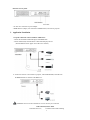
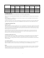
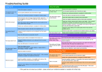
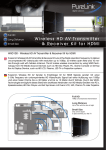
WHDI Video Transceiver System
Model #33-10530
User’s Manual
Table of Contents
1. Important information
1
2. Introduction
4
2.1 Overview
4
2.2 Main features
4
2.3 Packing Content
4
2.4 Control/Functions
5
A. Wireless HD transmitter
5
1.LED pattern on front panel
5
2.Interfaces on rear panel
5
B. Wireless HD receiver
6
1. LED pattern on front panel
6
2. Interface on rear panel
6
3.
Application/ Installation
4.
Standby Function
7-8
8
5.
Product Specifications
8
IMPORTANT INFORMATION
Please read this user manual before you use the Stellar Labs 33-10830 Transmitter/Receiver set. It contains important
operating information regarding the reliable use of this product.
Distributed Exclusively by:
MCM Electronics
www.mcmelectronics.com
1
DANGER: Be careful with electricity.
•
Power to all connected products must be switched OFF before installation. This includes televisions, monitors,
projectors, DVD players etc
•
To prevent electric shock, be sure this unit is connected to the proper type of electrical outlet
•
Make certain the power cord is routed well so that it will not be stepped on or pinched by heavy items
•
Avoid overloading electrical outlets or extension cords as this could result in electric shock or fire.
•
For protection from lightning, if this unit will be left unattended for a long period of time, it should be disconnected
from the power source.
•
•
WARNING:
This product should not be exposed to moisture. Objects containing liquids should not be placed on the product.
•
Put the receiver/transmitter in a property ventilated area, away from direct sunlight or any source of heat.
•
To reduce the risk of fire or electric shock, do not expose the receiver/transmitter to rain or moisture.
SPECIAL NOTICE:
This product should not be used in airports or medical facilities, where potential interference with critical equipment could
occur.
•
This product should not be used in locations where wireless signal causes abnormal video or audio interference.
1)
Place it on the table or desk steadily. Don’t try to move it when connected
2)
This device should stay away from refrigerator, washing machine or other metal furniture and crowded
locations.
•
This product has been tested and manufactured to comply with national safety rules. However, there is no guarantee
that interference will not occur in some particular installations.
•
This device is susceptible to interference from 5GHz wireless devices, such as routers.
•
Optimal Range between transmitter and receiver is 30m (open area ).
2
DECLARATION OF CONFORMITY
This device complies with Part 15C and Part 15E of FCC Rules.
Part 15: Subpart C—Radiated Emission Limits, Additional Provisions.
Part 15: Subpart E—Unlicensed National Information Infrastructure Devices.
This device complies with relative criteria CE certification.
EN 60950-1:2006
Information technology
Equipment
--- Safety ---
Part 1: General requirements
EN 300440-01 (V1.6.1)
Electromagnetic compatibility and Radio spectrum Matters (ERM);
Short range devices;
Radio equipment to be used in the 1 GHz to 40 GHz frequency range;
Part 1: Technical characteristics and test methods
EN 301489-03 (V1.4.1)
Electromagnetic compatibility and Radio spectrum Matters (ERM);
Electro Magnetic Compatibility (EMC) standard for radio equipment and services;
Part 3: Specific conditions for Short-Range Devices (SRD)
operating on frequencies between 9 kHz and 40 Ghz
EN 301489-17(V2.1.1)
Electromagnetic compatibility and Radio spectrum Matters (ERM);
Electro Magnetic Compatibility (EMC) standard for radio equipment;
Part 17: Specific conditions for Broadband Data Transmission Systems
EN 301893 (V1.5.1)
Broadband Radio Access Networks (BRAN);
5 GHz high performance RLAN;
Harmonized EN covering the essential requirements of article 3.2 of the R&TTE Directive
TRADEMARK INFORMATION
TRADEMARK INFORMATION: HDMI The HDMI Logo and High-Definition Multimedia Interface are trademarks
of HDMI Licensing LLC.
3
2. Introduction
2.1 Overview
The Model #33-10530 WHDI Video Transceiver System includes both a transmitter and receiver. This set can transmit
uncompressed 1080p/60Hz Deep Color A/V signal up to 30m (98’). The transmitter connects to the HDMI output of a variety
of high definition devices, including cable, satellite or HD set-top boxes, Blu-ray or DVD players, game consoles and PC
media centers. The receiver is this connected to the HDMI input of any LCD, LED, DLP or plasma display, or projector..
2.2 Main features
- Operating frequency range: 4.9 ~ 5.9GHz.
- DFS function
- Compact portable size
- Build in Omni-directional antennas
- Over 30m whole-house range ( LOS ) with no latency;
- IR remote control repeating
2.3 Package contents
Immediately upon arrival, check to verify the following items are included:
Main unit:
Sender and receiver set
Accessories:
USB Cable (A-A)
(2) Stands
U se r s’ m a n ua l
IR emitter
(2) AC Adaptors (5V, 3A)
4
User
Manual
2.4 Control/functions:
A. Transmitter
- Power LED (Red) indicates power on
- Video LED ( Green ) indicates HDMI connection is established
- Link LED ( Green ) indicates Wireless link between sender and receiver is established
- USB Slot used for firmware upgrade
Interface on rear panel.
- DC Jack: For connection of power adaptor
- IR Slot: For connection of included IR emitter
- HDMI Interface (input): For connection of HDMI media source
B. Receiver
- Power LED (Red) indicates power on
- Video LED ( Green ) indicates HDMI connection is established
- Link LED ( Green ) indicates Wireless link between sender and receiver is established
- USB Slot used for firmware upgrade
5
Interfaces on rear panel.
- DC Jack: For connection of power adaptor.
- HDMI Interface (output): For connection to HDMI monitor, television or projector
3.
Application/ Installation
Set up the connection of the Transmitter and Receiver
-Connect the transmitter multimedia player with HDMI cable
-Connect Infrared (IR) extender blaster to WD-200T and player device
(Stick the Blaster head to player device IR receive window)
2. Connect the receiver to the monitor or projector, with the HDMI cable, and make sure
the HDMI interface is selected on the HDTV set .
WARNING: Don’t move the transmitter or receiver once they are connected.
LED Connection States Table
x indicates LED is on,
* indicates Green LED is flashing
6
Status
Transmitter
Receiver
Power
Video
Link
Power
Video
Link
(RED)
(GREEN)
(GREEN)
(RED)
(GREEN)
(GREEN)
x
x
x
x
Power on
x
Link AV
x
x
x
x
x
Connectivity
x
x
x
x
x
Standby
x
x
x
4. Standby Function
When the transmitter and receiver are both powered on, the red LED will light immediately.
The green “link” LED will blink until the transmitter and receiver compete the link process. The green “link” LED will then
remain on.
When the HDMI source and HDMI monitor are both turned on, the green “video” LED will light, at this time the sender is
sending the HDMI signal to the receiver.
If either the video monitor or video source is turned off, after a time period of one minute, the set will go into standby mode,
and the “link” LED will turn off. On the side where the HDMI device was turned off, the “video” LED will also turn off.
5. Important Operation Notes
IR Remote Control
This set is capable of accepting IR commands at the receiver, and sending them to the IR emitter, plugged into the transmitter.
This enables source devices, such as BluRay players, cable or satellite boxes to be controlled at the location of the monitor or
projector. Note that the target for the IR control is on the front panel of the Wireless Receiver, and this must be kept in mind
when locating the receiver near the monitor.
Note that the IR remote control does not function while the units are in Standby mode. If you are at the location of the
monitor or projector, that monitor or projector must be turned on to “wake” the wireless transmitter and receiver from
Standby mode. Then the IR extender will function properly.
Syncing the Transmitter and receiver
Once the transmitter and receiver are “linked” it is not advised to move or relocate either unit. If the receiver (located at the
monitor or projector) is left in standby mode, and power is interrupted at the transmitter (for example to move it from a
BluRay player to a PC or laptop), it may be necessary to reset power to both the receiver and transmitter in order for them to
“link” to each other.
Use with laptop computers
Many laptop computers will automatically deactivate the HDMI output while the output is not in use. When connecting the
laptop to the HDMI Transmitter, it may be necessary to check the laptop to ensure the HDMI output is activated.
Range
Typical range of this device is 30m (98’), based on open line of sight (LOS) installation. This unit is capable of transmitting
through walls and floors of most residences, however overall range will be decreased. In cases of range issue, it is best to
locate the transmitter and receiver in open areas with few obstructions.
7
General Specifications
Product Name
Supported Video Resolution
HDMI Interface
Transmitter
Receiver
1080p, 720p, 1080i, 576i, 576p, 480p
Supports HDMI 1.3 Video Audio format and HDCP 1.2 with video
encryption.
Transmission Distance
30 meters Line of Sight ( LOS ).
Operating Frequencies
5.1~ 5.9GHz (with DFS function).
Band Width
40MHz
Frequency Stability
+/- 4PPM
Transmission Power
>=15dbm
>=17dbm
Receiving Sensitivity
<= -75dbm
<= -65dbm
System Latency
< 1 ms
Antenna
Omni-directional internal antennas.
Supporting link speeds
Up to 2.5G bps
Certification
FCC, CE
Regulations
WHDI 1.0
Power Supply
AC 100~ 240V , 5V 3A DC Power Adaptor
IR function
2.5mm Phone Jack, External IR
Build-in Infrared Remote-control
Blaster
Receiver Module
Working temperature
Dimensions (mm)
0 °C – 70 °C
146 (L) x 93 (W) x 25 (H) – each
Weight
110g
8
unit