1
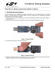
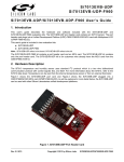
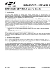
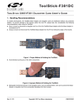
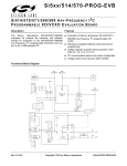
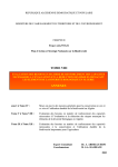
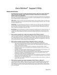
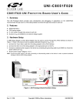
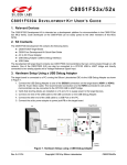
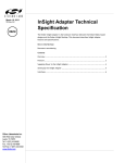
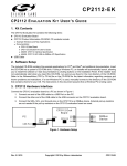
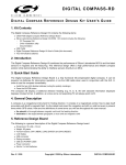
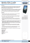
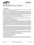
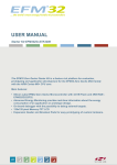
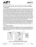
Si7005USB-DONGLE EVALUATION DONGLE KIT FOR THE Si7005 TE M PE R A T U R E A N D H U M I D I T Y S E N S O R 1. Introduction The Si7005 is a relative humidity and temperature environmental sensor in a 4 mm x 4 mm QFN package. Access to the sensor output is via a standard I2C digital interface. The Si7005 is a highly-integrated device incorporating a humidity sensor, temperature sensor, signal conditioning, an analog-to-digital converter, control logic, and an I2C interface. 2. Evaluation Kit Description This document describes the operation of the Silicon Laboratories Si7005USB-DONGLE Rev 1.0 evaluation kit. The Si7005 evaluation kit and accompanying graphical user interface software allow the user quick and easy access to the features and functions of the Si7005 sensor as well as enabling the evaluation of the sensor’s performance. The evaluation kit includes the following: Si7005USB-DONGLE evaluation board consisting of one Si7005 sensor graphical user interface software for complete control of the Si7005 sensor (Windows XP, VISTA, or 7 required) Windows Si7005 C8051F381 Figure 1. Si7005USB-DONGLE Figure 2. Si7005-EVB (Ordered Separately) Rev. 0.2 10/12 Copyright © 2012 by Silicon Laboratories Si7005USB-DONGLE Si7005USB-DONGLE 3. Software Setup It is important that the software be installed before connecting the USB dongle to the PC; this ensures that the software drivers are correctly installed. To set up the software, run the file, setup.exe, from the supplied software installation disk. The Si7005 demo platform was developed based on National Instruments LabView™ platform. To install it, you must accept the National Instruments end-user license agreement shown in Figure 3. Figure 3. National Instruments Software License Agreement Continue through the following screens, which track the Graphical User Interface installation. 2 Rev. 0.2 Si7005USB-DONGLE Figure 4. Start Installation Screen Rev. 0.2 3 Si7005USB-DONGLE Figure 5. Installer Update Screen After this screen, you will see the installer for the Si7005 device drivers. 4 Rev. 0.2 Si7005USB-DONGLE Figure 6. Device Drivers Installer Screen Rev. 0.2 5 Si7005USB-DONGLE 4. Hardware Setup and Software Operation Once the GUI installation is complete, connect the Si7005 USB dongle to your PC. Your PC should automatically recognize the USB dongle and use the newly-installed driver. Next, find the icon for the Si7005 GUI, which should be easily found under recently-installed programs from the start menu, under ProgramsSilicon LaboratoriesSi700x Evaluation Software or at C:\program files\Silicon Laboratories\Si700x\. With all the hardware plugged in and once your PC identifies the USB dongle, launch the GUI. The GUI itself is simple to use. Figure 7 shows a screen shot of the GUI. Figure 7. GUI Screen 6 Rev. 0.2 Si7005USB-DONGLE The USB dongle contains one Si7005 relative humidity and temperature sensor and can also support one additional Si7005 sensor at connector J2 by connecting a Si7005-EVB (ordered separately). To start the evaluation, click the “INIT” button, the GUI will recognize how many sensors are connected. Select temperature units by clicking on the “Select Temperature Units” button, the button label will toggle between “Deg C” and “Deg F” indicating the selection of either degrees Celsius or degrees Fahrenheit. In the “Enter Sample Interval (seconds)” number box, the time interval between samples can be entered, a value between 1 and 65535 seconds can be entered. The Si7005 on-chip heater can be enabled/disabled using the “On-chip Heater” toggle button. The heaters of all the connected sensors are controlled simultaneously. The upper chart by default displays temperature; this can be changed to dew point by clicking on the selection box located directly under the Silicon Labs logo. When logging data to file, the upper chart should be set to display temperature since dew point is already automatically logged to file. The default Y-axis range on each chart is from 0 to 100. To change this range, simply click on the upper or lower value on the chart axis and type in an alternative value. The axis can also be configured to auto-range to the displayed data by right-clicking on the chart and selecting “Autoscale Y”. The same configuration changes can be made to the X-axis. If a log of the data is desired, click “Create Log File?” button to “Yes”. Click “START” to begin collecting data. If “Create Log File?” is enabled, a dialog box will appear requesting a file name and save location. Note that the “Create Log File?” button must be set to “YES” before clicking on the “Start” button in order to log data. The time base of the log file can be chosen to be absolute date and time or relative time in seconds. To stop data collection, click “STOP”. To exit the GUI click “QUIT”. The GUI automatically adjusts for the temperature and non-linearity effect of the RH-sensitive film of the Si7005 The data logged to file is saved in a tab delimited text file format, which can be easily opened in a spreadsheet application such as Microsoft Excel, as shown in Figure 8. Figure 8. Logged Data Displayed in Excel with Absolute Date and Time time Base Rev. 0.2 7 Si7005USB-DONGLE Figure 9. Logged Data Displayed in Excel with Relative Time Base in Seconds 4.1. Calculation of Dew Point Value The Si7005 measures both temperature (T) and relative humidity (RH). These two values can be used to approximate the dew point (Td). b T,RH T d = ------------------------------a – T,RH Where aT RH T,RH = ------------- + ln ---------- 100 b+T a = 17.625 b = 243.04 The calculation used is based on the August-Roche-Magnus approximation for the saturation vapour pressure of water in air as a function of temperature, it is considered valid for: 0 °C < T < 60 °C 1% < RH < 100% 0 °C < Td < 50 °C 8 Rev. 0.2 Si7005USB-DONGLE 5. Si7005 USB Dongle Description The USB Dongle facilitates communication between the Si7005 and the PC. This function is enabled by the Silicon Laboratories' C8051F381 microcontroller. The pin connections for connector J2 are shown in Figure 10. A full circuit diagram of the board is shown in Figure 11. 6 VDD 1 5 CS 2 4 3 Ribbon Connector USB Dongle GND SDA Ribbon Connector Si7005 EVB 3 4 2 PROG 5 1 SCL 6 Figure 10. Ribbon Cable Pin Assignments 5.1. Si7005 USB Dongle Schematic The Si7005USB-DONGLE is a simple board containing an Si7005 relative humidity and temperature sensor, a C8051F381 USB microcontroller, a USB type A connector, and an auxiliary connector for connection to a second Si7005 sensor. Discrete component requirements are minimal, demonstrating the ease-of-use of the Si7005. Rev. 0.2 9 +V DD+ GND P1 USB TYPE A SH SH 6 5 1 2 3 4 +3V3 Rev. 0.2 C7 0.1uF RESETn C5 0.1uF D1 SP0503BAHT C6 4.7uF 1K 6 GND P2.0 P2.1 P2.2 P2.3 P2.4 P2.5 P2.6 P2.7 P1.0 P1.1 P1.2 P1.3 P1.4 P1.5 P1.6 P1.7 P0.0 P0.1 P0.2 P0.3 P0.4 P0.5 P0.6 P0.7 18 17 16 15 14 13 12 11 26 25 24 23 22 21 20 19 2 1 32 31 30 29 28 27 U2 C8051F381 R6 332 D2 AMBER R1 10K R2 10K R3 2K SCL2 SDA2 CS2 R4 2K Figure 11. USB Dongle Circuit Schematic VDD 7 8 REGIN VBUS RST/C2CK P3.0/C2D DD+ GND C2CK C2D J1 R11 R10 10K 9 10 5 4 C2 0.1uF 0 0 0 R8 R9 0 R7 R5 C4 0.1uF 6 5 4 3 2 1 25 EPAD DNC DNC SDA SCL DNC GND TP3 SDA SCL U1 DNC TP4 TP1 VDD C3 4.7uF CS DNC Si7005 DNC 9 24 DNC 7 23 GND 8 22 VDD 21 Cext DNC TP2 GND TP5 10 20 GND 11 19 GND DNC DNC CS DNC DNC DNC DNC DNC 12 10 3 C1 4.7uF 13 14 15 16 17 18 6 5 4 3 2 1 FH12 J2 6 5 4 3 2 1 Si7005USB-DONGLE Si7005USB-DONGLE 5.2. Si7005 USB Dongle Board Layers Figure 12. Si7005 Dongle Board Layout Top Layer Figure 13. Si7005 Dongle Board Layout Bottom Layer Note from Figures 1, 12, and 13, that there is no ground plane around the Si7005 and that there is a cutout in the PCB between the Si7005 and other circuitry. While these are not requirements for successful operation of the Si7005, they do (in the case of the dongle board) provide thermal isolation from heat sources, such as the host PC and MCU circuitry. The intention of this evaluation board layout is to demonstrate the concept of thermal isolation between the Si7005 and the system board. In many applications, the system designer will use the Si7005 to sense the temperature of the air around it and not that of the system PCB. Rev. 0.2 11 Si7005USB-DONGLE 6. Si7005-EVB Description 6.1. Si7005 EVB Schematic 6L *1' '1& '1& '1& (3$' )+ - & X) & 6'$ '1& X) '1& 12 Rev. 0.2 Figure 14. Si7005 Evaluation Board Schematic '1& '1& &6 '1& '1& '1& '1& 8 9'' 6&/ &H[W '1& '1& *1' '1& *1' *1' '1& The evaluation board is a simple board containing just the Si7005 sensor, two capacitors and a ribbon connector for connection to the USB dongle board. The circuit diagram and layout are shown in Figures 14, 15 and 16. Si7005USB-DONGLE 6.2. Si7005 Evaluation Board Layers Figure 15. Si7005 Evaluation Board Layout Top Layer Figure 16. Si7005 Evaluation Board Layout Bottom Layer Rev. 0.2 13 Si7005USB-DONGLE 7. Additional Reference Resources Si7005 data sheet AN607: Si70xx Humidity Sensor Designer's Guide 14 Rev. 0.2 Si7005USB-DONGLE DOCUMENT CHANGE LIST Revision 0.1 to Revision 0.2 Rev. 0.2 15 Si7005USB-DONGLE CONTACT INFORMATION Silicon Laboratories Inc. 400 West Cesar Chavez Austin, TX 78701 Tel: 1+(512) 416-8500 Fax: 1+(512) 416-9669 Toll Free: 1+(877) 444-3032 Please visit the Silicon Labs Technical Support web page: https://www.silabs.com/support/pages/contacttechnicalsupport.aspx and register to submit a technical support request. Patent Notice Silicon Labs invests in research and development to help our customers differentiate in the market with innovative low-power, small size, analog-intensive mixed-signal solutions. Silicon Labs' extensive patent portfolio is a testament to our unique approach and world-class engineering team. The information in this document is believed to be accurate in all respects at the time of publication but is subject to change without notice. Silicon Laboratories assumes no responsibility for errors and omissions, and disclaims responsibility for any consequences resulting from the use of information included herein. Additionally, Silicon Laboratories assumes no responsibility for the functioning of undescribed features or parameters. Silicon Laboratories reserves the right to make changes without further notice. Silicon Laboratories makes no warranty, representation or guarantee regarding the suitability of its products for any particular purpose, nor does Silicon Laboratories assume any liability arising out of the application or use of any product or circuit, and specifically disclaims any and all liability, including without limitation consequential or incidental damages. Silicon Laboratories products are not designed, intended, or authorized for use in applications intended to support or sustain life, or for any other application in which the failure of the Silicon Laboratories product could create a situation where personal injury or death may occur. Should Buyer purchase or use Silicon Laboratories products for any such unintended or unauthorized application, Buyer shall indemnify and hold Silicon Laboratories harmless against all claims and damages. Silicon Laboratories and Silicon Labs are trademarks of Silicon Laboratories Inc. Other products or brandnames mentioned herein are trademarks or registered trademarks of their respective holders. 16 Rev. 0.2