1
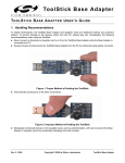
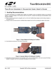
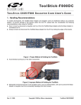
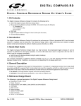
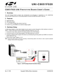
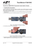
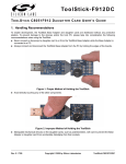
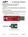
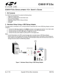
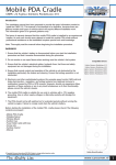
To o l Sti c k D e b u g A d a p t e r TO O L S T I C K D E B U G A D A P T E R U S E R ’ S G U I D E 1. Handling Recommendations To enable development, the ToolStick Base Adapter and daughter cards are distributed without any protective plastics. To prevent damage to the devices and/or the host PC, please take into consideration the following recommendations when using the ToolStick: Never connect or disconnect a daughter card to or from the ToolStick Base Adapter while the Base Adapter is connected to a PC. Always connect and disconnect the ToolStick from the PC by holding the large plastic connector. Figure 1. Proper Insertion Avoid directly touching any of the other components. Figure 2. Improper Insertion Manipulate mechanical devices on the daughter cards, such as potentiometers, with care to prevent the base adapter or daughter card from accidentally dislodging from their socket. Rev. 0.1 9/06 Copyright © 2006 by Silicon Laboratories ToolStick Debug Adapter ToolSt ick Debug Adapter 2. Contents The ToolStick Debug Adapter package contains the following items: ToolStick Debug Adapter (USB to Debug Interface) 7” Ribbon Cable Note: The ToolStick Debug Adapter requires a ToolStick Base Adapter for proper operation. 3. ToolStick Debug Adapter Specifications The ToolStick Debug Adapter, in conjunction with a ToolStick Base Adapter, provides the interface between the PC’s USB port and the target device’s in-system debug/programming circuitry. The 10-pin debug ribbon cable connects the adapter to the target board and the target device’s debug interface. The ToolStick Debug Adapter supports both Silicon Laboratories JTAG and C2 debug interfaces. Power is provided to the adapter from the USB connection to the PC. The ToolStick Debug Adapter is capable of providing power to a circuit board via pin 10 of the DEBUG connector. See the respective kit user’s guide for instructions on powering a target board from this source. Please note that not all of the Silicon Laboratories MCU development boards support being powered from the debug adapter. Table 1 shows the pin definitions for the debug ribbon cable connector. Notes: The ToolStick Debug Adapter requires a target system clock of 32 kHz or greater. With the default settings, the ToolStick Debug Adapter can supply up to 75 mA to a target system. Table 1. ToolStick Debug Adapter DEBUG Connector Pin Descriptions Pin # Description 1 VDD 2,3,9 GND (Ground) 4 TCK (C2D) 5 TMS 6 TDO 7 TDI (C2CK) 8 Unconnected 10 USB Power Figure 3. ToolStick Base Adapter with ToolStick Debug Adapter Daughter Card 2 Rev. 0.1 To olSt ick Debug Adapter 4. Hardware Setup using a ToolStick Debug Adapter Configure the ToolStick Debug Adapter 1. Place the jumper J1 in the appropriate position for the I/O voltage of the Target Board being used. Connect pins 1 and 2 (VREG and VIO) for 2.5 V I/O or connect pins 2 and 3 (VDD and VIO) for 3.3 V I/O. 2. If the Target Board will be powered from the ToolStick Debug Adapter, place a jumper on header J2. If the Target Board will be separately powered, ensure that no jumper is installed on header J2. Note: Powering the Target Board from the ToolStick Debug Adapter and a separate power supply at the same time could cause damage to the ToolStick Base Adapter and/or the Target Board. J3 P2 J1 J2 Figure 4. ToolStick Debug Adapter Jumpers Connect the ToolStick Debug Adapter to the Target Board as shown in Figure 5. 1. If not already assembled, insert the ToolStick Debug Adapter into a ToolStick Base Adapter. 2. Connect the 10-pin ribbon cable from the ToolStick Debug Adapter to the Target Board debug header. 3. Connect one end of the USB cable to the USB connector on the ToolStick Debug Adapter. 4. Connect the other end of the USB cable to a USB port on the PC that will run the Silicon Laboratories IDE. 5. Connect the AC/DC power adapter to the power jack on the target board, or configure the board to receive power from the ToolStick Debug Adapter (see the Target Board Kit User’s Guide for configuration options). Notes: Use the Reset button in the IDE to reset the target when connected using a ToolStick Debug Adapter. Remove power from the target board and the ToolStick Debug Adapter before connecting or disconnecting the ribbon cable from the target board. Connecting or disconnecting the cable when the devices have power can damage the device and/or the ToolStick Debug Adapter. ToolStick Base Adapter Debug Adapter Target Board Figure 5. Hardware Setup Using a ToolStick Debug Adapter Rev. 0.1 3 ToolSt ick Debug Adapter 5. Software Setup using a ToolStick Debug Adapter The Silicon Laboratories Integrated Development Environment (IDE), along with other software tools, are provided for device development and debugging. The IDE is available for download from the Silicon Laboratories website and is also available on microcontroller development kit CD-ROMs. Once the IDE has been installed and the hardware has been connected as shown in Section 4, follow the steps below to built a project, connect and download to a target board using the ToolStick Debug Adapter. 1. Select Project → Open Project... to open a previously saved project. 2. Before connecting to the target device, several connection options may need to be set. Open the Connection Options window (shown in Figure 6) by selecting Options → Connection Options... in the IDE menu. 3. Select USB Debug Adapter in the “Serial Adapter” section. 4. If more than one adapter is connected, choose the appropriate serial number from the drop-down list. 5. Next, the correct “Debug Interface” must be selected. Check the Debug Interface corresponding to the Silicon Laboratories device on the target board. 6. Once all the selections are made, click the OK button to close the window. 7. Click the Connect button in the toolbar or select Debug → Connect from the menu to connect to the device. 8. Download the project to the target by clicking the Download Code button in the toolbar. 9. Save the project when finished with the debug session to preserve the current target build configuration, editor settings and the location of all open debug views. To save the project, select Project → Save Project As... from the menu. Create a new name for the project and click on Save. 4 Rev. 0.1 Figure 6. Connection Options To olSt ick Debug Adapter 6. ToolStick Debug Adaper Schematic Rev. 0.1 5 ToolSt ick Debug Adapter CONTACT INFORMATION Silicon Laboratories Inc. 400 West Cesar Chavez Austin, TX 78701 Tel: 1+(512) 416-8500 Fax: 1+(512) 416-9669 Toll Free: 1+(877) 444-3032 Email: [email protected] Internet: www.silabs.com The information in this document is believed to be accurate in all respects at the time of publication but is subject to change without notice. Silicon Laboratories assumes no responsibility for errors and omissions, and disclaims responsibility for any consequences resulting from the use of information included herein. Additionally, Silicon Laboratories assumes no responsibility for the functioning of undescribed features or parameters. Silicon Laboratories reserves the right to make changes without further notice. Silicon Laboratories makes no warranty, representation or guarantee regarding the suitability of its products for any particular purpose, nor does Silicon Laboratories assume any liability arising out of the application or use of any product or circuit, and specifically disclaims any and all liability, including without limitation consequential or incidental damages. Silicon Laboratories products are not designed, intended, or authorized for use in applications intended to support or sustain life, or for any other application in which the failure of the Silicon Laboratories product could create a situation where personal injury or death may occur. Should Buyer purchase or use Silicon Laboratories products for any such unintended or unauthorized application, Buyer shall indemnify and hold Silicon Laboratories harmless against all claims and damages. Silicon Laboratories and Silicon Labs are trademarks of Silicon Laboratories Inc. Other products or brandnames mentioned herein are trademarks or registered trademarks of their respective holders. 6 Rev. 0.1