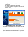
1
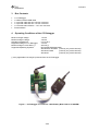
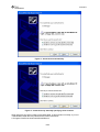
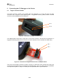
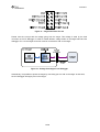
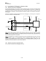
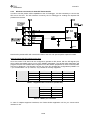
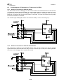
CC Debugger User’s Guide SWRU197C swru197c Table of Contents 1 Introduction ............................................................................................................................3 2 Abbreviations and Acronyms ................................................................................................3 3 Box Contents..........................................................................................................................4 4 Operating Conditions of the CC Debugger ...........................................................................4 5 Initial Steps .............................................................................................................................5 5.1 5.2 6 Installing the USB driver........................................................................................................5 Supported PC Tools..............................................................................................................8 Connecting the CC Debugger to the Device..........................................................................9 6.1 6.2 6.2.1 6.2.2 6.2.3 6.3 6.3.1 6.3.2 7 Target Connector Details ......................................................................................................9 Connecting the CC Debugger to a System on Chip .............................................................11 Minimum connection for debugging ............................................................................................................................ 11 Minimum connection for SmartRF Studio ................................................................................................................... 11 Minimum connection for SmartRF Packet Sniffer ...................................................................................................... 12 Connecting the CC Debugger to a Transceiver (CC2520)....................................................13 Minimum connection for SmartRF Studio ................................................................................................................... 13 Minimum connection for SmartRF Packet Sniffer ...................................................................................................... 13 Using the CC Debugger........................................................................................................14 7.1 8 Understanding the LED .......................................................................................................14 Updating the Firmware.........................................................................................................15 8.1 8.2 8.3 8.4 Updating the firmware automatically in SmartRF Studio.......................................................15 Updating the firmware manually in SmartRF Flash Programmer ..........................................16 Forced boot recovery mode.................................................................................................17 Resurrecting the CC Debugger ...........................................................................................18 9 Troubleshooting ...................................................................................................................20 10 Schematics ...........................................................................................................................21 11 References............................................................................................................................21 12 Document History.................................................................................................................21 2/22 swru197c 1 Introduction The CC Debugger can be used to debug and program the flash of any of the RF System-on-Chip (SoC) devices from Texas Instruments (except the CC1010 and CC430). The PC Tools available for these purposes are the SmartRF™ Flash Programmer from Texas Instruments and IAR Embedded Workbench® for 8051 from IAR Systems. It is also possible to control and run tests on the devices from SmartRF™ Studio. When using SmartRF Studio, the debugger supports the CC2520 transceiver in addition to the SoC devices. 2 Abbreviations and Acronyms CSn DC DD DUT GND LED MISO MOSI RF SCLK SoC SPI USB Vdd Chip Select (active low) Debug Clock Debug Data Device Under Test Ground Light Emitting Diode Master In Slave Out Master Out Slave In Radio Frequency Serial Clock System on Chip Serial Peripheral Interface Universal Serial Bus Positive Voltage on target 3/22 swru197c 3 4 Box Contents 1 CC Debugger 1 USB-A to Mini-B USB cable 1 10-pin flat cable with 2x5 2.54 mm connector 1 10-pin flat cable with 2x5 1.27 mm connector 1 Converter board 2.54mm – 1.27 mm connector Documentation Operating Conditions of the CC Debugger Minimum target voltage: Maximum target voltage: Operating temperature: Regulated voltage on CC Debugger: Maximum target current draw (*): Supported Operating Systems: 1.2 Volt 3.6 Volt 0C to 85C 3.3 Volt 200 mA (*) Microsoft® Windows® 2000 Windows XP SP2/SP3 (currently only 32 bit versions) Windows Vista® (currently only 32 bit versions) Windows 7 (currently only 32 bit versions) (*) Only applicable if the target is powered from the CC Debugger Figure 1 - CC Debugger connected to a SoC Battery Board with a CC2530EM 4/22 swru197c 5 5.1 Initial Steps Installing the USB driver To get the required USB driver for the CC Debugger, it is necessary to install one of the tools listed below: SmartRF Studio SmartRF Flash Programmer IAR Embedded Workbench 8051 www.ti.com/lit/zip/swrc046 www.ti.com/lit/zip/swrc044 www.iar.com/ew8051 When the CC Debugger is connected to the PC for the first time, Windows will detect the USB device and prompt the user to identify the driver to use. Figure 2 - Windows detects the USB device If SmartRF Studio or SmartRF Flash Programmer has been installed, the driver required for correct interaction between the PC and CC Debugger has been registered in the operating system. In that case, it is possible to let Windows find the driver automatically to finalize the association between the device and driver (see Figure 3). If only IAR EW8051 has been installed, the driver has not been registered, so it is necessary to locate the driver manually (see Figure 4 and Figure 5). 5/22 swru197c Figure 3 - Install driver automatically Figure 4 - Install driver by manually specifying driver location When specifying the driver (cebal.sys and associated .inf files) location manually, try one of <IAR EW8051 install directory>\8051\drivers\Texas Instruments C:\Program Files\Texas Instruments\Extras\Drivers 6/22 swru197c Figure 5 - Install driver by manually specifying driver location (cont.) Figure 6 - Let Windows copy the required driver to the system folder 7/22 swru197c Figure 7 - Driver installation completed At this point, the USB driver installation has finished. It is possible to verify that the driver installation succeeded by opening the Device Manager and check that the CC Debugger is listed under “Cebal controlled devices”. Figure 8 - Verify correct driver installation 5.2 Supported PC Tools Currently, the CC Debugger can be used together with the following PC Tools In Circuit Debugging Flash Programming RF Testing Packet Sniffing IAR Embedded Workbench for 8051 SmartRF Flash Programmer SmartRF Studio SmartRF Packet Sniffer The debugger will operate as the interface between the RF device and the tools listed above. Please ensure correct connection between the device and CC debugger before starting to use the tools. This will be covered in the next chapter. 8/22 swru197c 6 6.1 Connecting the CC Debugger to the Device Target Connector Details The target connector, located on the lateral side of the debugger, is a 10-pin 2x5 2.54 mm pitch connector with a direction coded plastic guide. A suggested matching (male) surface mounted connector would be BB02-HP from GradConn. Pin 1 Pin 2 Figure 9 - Placement of Target Connector Pins The adapter board, which has a 10-pin 2x5 1.27 mm pitch connector, has the same pin placement. A suggested matching (male) surface mounted connector would be STL21-A01VXX from MPE Garry. Pin 1 Pin 2 Figure 10 - Placement of Target Connector Pins on Adapter Board The pin-out of the target connector is shown in Figure 11. Note that not all of these pins need to be connected to the target device for programming and debugging. Only Vdd, GND, DD, DC and RESET are required for System on Chips. The other pins are optional and/or for special features. 9/22 swru197c Figure 11 - Target Connector Pin-out Please note the concept with the voltage going from the target. This voltage is used by the level converter on the CC Debugger in order to handle different voltage levels on the target board and the debugger. Pin 2 on the target connector must be connected to Vdd on the target. Figure 12 - Voltage from target to CC Debugger Alternatively, it is possible to power the target by connecting pin 9 to Vdd on the target. In that case, the CC Debugger will supply 3.3V to the target. 10/22 swru197c 6.2 6.2.1 Connecting the CC Debugger to a System on Chip Minimum connection for debugging For successful debugging of a TI CC2xxx or CC11xx System on Chip, connect the two debug signals Debug Data (DD) and Debug Clock (DC) and the reset signal RESETn to the device. In addition, the CC Debugger must be connected to GND and Vdd on the board. Vdd is used as an input to the level shifters on the CC Debugger, thus allowing different operating voltage on the target than internally on the debugger. Note that it is possible to power the target board from the debugger by connecting the 3.3V signal on pin 9 on the connector to the target board. Vdd CC Debugger Connector NOTE 1 Vdd CCxxxx System-on-Chip 10 kΩ Vdd GND 2 3 4 5 6 7 8 9 10 DC (Debug Clock) P2.2 P2.1 DD (Debug Data) SoC 2.7 kΩ RESETn RESETn NOTE 2 1 nF 3.3V from debugger. Can optionally be used to power the target board 1 GND Note 1: Some early revisions of certain SoCs (CC2430, CC2510 and CC1110) needed an external pull-up to avoid unwanted transitions on the debug clock line during chip reset – thus inadvertently setting the device in debug mode. All new revisions of all SoCs now have an internal pull-up on P2.2, so this external component is not required. Note 2: The RESETn pin is sensitive to noise and can cause unintended reset of the chip. For reset lines susceptible to noise, it is recommended to add an external RC filter. Please refer to the respective SoC datasheet and reference designs for recommended RESET circuitry. The CC Debugger supports slow transitions on the reset line, using a 2 ms delay between any transition on the RESET line and other transitions on the DC and/or DD lines. 6.2.2 Minimum connection for SmartRF Studio The connection is identical as for debugging of the SoC. 11/22 swru197c 6.2.3 Minimum connection for SmartRF Packet Sniffer 1 nF In order to use the packet sniffer capabilities of the CC Debugger, it is also necessary to connect the SPI bus to the SoC. The SPI interface is used by the CC Debugger for reading the captured RF packets from the SoC. Note that the packet sniffer will overwrite the flash of the SoC with special packet capture firmware. Note concerning the SPI interface to the SoC All of the current TI RF SoCs can be configured to operate as SPI slaves, with the SPI signals (CS, SCLK, MISO and MOSI) going to one of the USART peripherals. The packet sniffer application will program the SoC with firmware that configures one of the USART peripherals in order to communicate with the CC Debugger. The firmware can use any of the four possible pin configurations (USART 0 or 1, pin out alternative 1 or 2). However, only a subset is currently supported: CC2430 CC2530 CC1110 CC2510 USART0, alt 1 OK OK USART0, alt 2 - USART1, alt 1 - USART1, alt 2 OK OK OK OK Table 1 - Supported SPI connections (marked OK) SCLK CS MOSI MISO USART0, alt 1 P0.5 P0.4 P0.3 P0.2 USART1, alt 2 P1.5 P1.4 P1.6 P1.7 Table 2 - USART pin out details In case of multiple supported interfaces, the Packet Sniffer application will let you choose which interface to use. 12/22 swru197c 6.3 6.3.1 Connecting the CC Debugger to a Transceiver (CC2520) Minimum connection for SmartRF Studio The SPI interface on the CC Debugger can be used to interface the CC2520 transceiver. Note that the CC Debugger operates as the SPI Master. In a multi master system, it would be necessary to have a jumper or switch to make sure the debugger output signals (RESET, VREG_EN, CSn, SCLK and MOSI) do not interfere with the other SPI master on the board. The other SPI master would typically be the microcontroller on the board. The CC2520 signal VREG_EN must be connected to the DD pin on the connector (pin 4). 6.3.2 Minimum connection for SmartRF Packet Sniffer The connection is similar as for the SmartRF Studio case. The only difference is that the CC2520 signal GPIO3 must be connected to the DC pin on the connector (pin 3). This pin is used to generate events on the CC Debugger when a packet is received. 13/22 swru197c 7 Using the CC Debugger After having connected the debugger to the target device, the debugger can be powered up by plugging in the USB cable. The debugger will immediately start a device detection process, looking for all known devices. If no devices are detected, the LED will be RED. If a device is detected, the LED will be GREEN. If the LED is GREEN, it is possible to start using the debugger together with one of the supported PC tools. 7.1 Understanding the LED OFF: The debugger has no power or there is no valid application/firmware on the debugger. Make sure the debugger is properly powered via the USB cable or try to resurrect the debugger using the method described in chapter 8.4. RED LED Blinking: The Debugger is in Boot Recovery Mode. The debugger will briefly enter this state while the firmware is being upgraded (see chapter 8). The board might also enter this state if the firmware is corrupt or if the user has manually forced to board to start up in the special “boot recovery mode” (section 8.3). To go out of the state, reset the debugger by pressing the “Reset” button or by power-cycling the device. If the LED is still blinking, reprogram the unit by using the Flash Programmer Application. RED LED ON: No device detected. This might be due to old firmware on the CC Debugger. New devices might not be supported with the current firmware on the debugger. Please refer to chapter 8 for the firmware upgrade procedure. There might also be a problem with the hardware connection. Check the connection to device and make sure the target board is properly powered and that Vdd on the target board is connected to pin 2 on the debug connector. Press and release the reset button to retry the target device detection. GREEN LED ON: The target device has been properly detected. It is possible to start using the supported tools (see chapter 5.2). 14/22 swru197c 8 Updating the Firmware In order to make sure the CC Debugger works seamless with your device, it is important that it has the latest and greatest firmware. This chapter will describe how you can upgrade the firmware automatically from SmartRF Studio or manually from SmartRF Flash Programmer. The chapter will also describe how to resurrect a seemingly broken debugger. 8.1 Updating the firmware automatically in SmartRF Studio Updating the firmware on the CC Debugger can be done automatically by SmartRF Studio. Please follow the few steps described below. 1. Start SmartRF Studio. 2. Disconnect the debugger from any target board, and connect it to the PC via the USB cable. The debugger will appear in the list of connected devices in the lower part of the SmartRF Studio startup panel. Figure 13 - Auto FW upgrade 3. Double click on the item in the list, and a new window will appear. 15/22 swru197c Figure 14 - Auto FW upgrade 4. Click "Yes" and let SmartRF Studio do the rest. Figure 15 - Auto FW upgrade 5. Click "Done" and you're good to go. The device should appear in the list of connected devices, now showing the new firmware revision. 8.2 Updating the firmware manually in SmartRF Flash Programmer You can also update the firmware manually using SmartRF Flash Programmer. You can use this method if you like to have full control of the firmware image to be programmed on the controller of the debugger (i.e. programming custom firmware or old firmware revisions). 1. Start SmartRF Flash Programmer and select the tab called “EB application (USB)”. This tab will let you program compatible firmware on the CC Debugger (or evaluation boards) via the USB interface (i.e. no external programming device required). 16/22 swru197c 2. Disconnect the debugger from any target board, and connect it to the PC via the USB cable. The debugger will appear in the list of connected devices. Chip type will be listed as N/A. 3. Select the flash image you want to program on the debugger. Normally, you would select: 1 C:\Program Files\Texas Instruments\Extras\ccdebugger\cebal_fw_srf05dbg.hex 4. Select the action “Erase, program and verify” 5. Click the “Perform actions” buttons. The programming procedure will start. Note that this will take several seconds. 6. The CC Debugger will reappear in the list of connected devices, now showing the new firmware revision in the device list. 7. Done! 8.3 Forced boot recovery mode If, for some reason, the firmware update fails and the CC Debugger appears to be non responsive, there is a way to force the board to only run the bootloader and stop all further execution. In this mode, no attempts will be made to start the firmware, and the board will only allow the user to perform a new firmware upgrade over USB. Disconnect the debugger from any power source and open the plastic enclosure. Figure 16 - Internal view of CC Debugger Short circuit the pins as depicted in Figure 17: P1.6 on the CC2511 must be connected to GND during the power-on reset to enter boot recovery mode. 1 Assuming default installation path of SmartRF Flash Programmer. 17/22 swru197c Figure 17 - Short-circuit pins for boot recovery mode When reconnecting the USB cable, the LED will start to blink with a RED light. This indicates that the bootloader is running and that the debugger is in boot recovery mode. At this point, follow the same firmware programming steps as describe at the beginning of this chapter. Please also note that the boot recovery mode can be used as a check to verify that the bootloader on the debugger is working. 8.4 Resurrecting the CC Debugger If the CC Debugger appears to be completely dead when applying power, there is a way to “unbrick” the board. The method consists of reprogramming the bootloader on the debugger using the debug connector inside the box. This will require an extra programming device. When opening the box, locate the debug connector header next to the target connector. Connect this header to another CC Debugger or to a SmartRF05EB, as shown in Figure 18. When using SmartRF05EB, connect a 10-pin flat cable from the “Ext SoC Debug” plug (P3) on the EB to the “USB Debug” plug (P2) on the CC Debugger. The dead debugger needs power, so connect the USB cable. Turn on the EB - it should detect the USB Controller (CC2511) on the debugger. Figure 18 - Programming the bootloader on the CC Debugger using SmartRF05EB Next, use the SmartRF Flash Programmer to program the bootloader on the debugger. Follow these five steps: 18/22 swru197c 1. After starting the application, select the “EB Bootloader” tab. 2. In the upper left corner, select device: Use SmartRF05EB regardless of the device being used to program the debugger. 3. Next, select which flash image to program. The bootloader image is included when installing the flash programmer and it is usually located at “C:\Program Files\Texas Instruments\Extras\ccdebugger”. 4. It is also necessary to give the debugger a unique ID number – any 4 digit number will work. This number is used by the driver on the PC to uniquely identify devices if more than one is connected at the same time. 5. Select “Erase, program and verify” 6. Press the “Perform Actions” buttons. The firmware upgrade takes a few seconds. 1 2 3 4 5 6 Figure 19 - SmartRF Flash Programmer - Updating the bootloader Once the bootloader is programmed, you might be asked to install a USB driver on the PC. Just follow the same procedure as when the debugger was connected to the PC the first time (see chapter 5). The RED LED on the debugger should now be blinking, indicating that the bootloader is running but that no application has been loaded. If the RED LED is off, there is probably something wrong with the hardware. The application (the debugger firmware) can be programmed over USB by following the same sequence as outlined at the beginning of this chapter. It is also possible to use the Flash Programmer. Select the “EB application (USB)” tab and follow the similar steps as above for the bootloader. This time, select the CC Debugger from the device list, select the firmware image to upload and click the “Perform actions” button. The RED LED should now be turned on, indicating success. 19/22 swru197c 9 Troubleshooting Q1 Help! The debugger does not detect the SoC. What should I do? A1 There are several things to check. Upgrade the firmware. Many CC Debuggers have old firmware that will not automatically detect newer devices, like CC2533 and CC2540. These devices need firmware version 13 or newer. Refer to chapter 8 for further instructions. Check that the cable is oriented correctly and that the pins are connected to the right signals on the debugger. Check that the debugger gets power from the target. This is required in order for the level converters to work. Check that the ground plane on the target is connected to the ground plane on the debugger. This is normally achieved through the target connector. Note that since the ground planes are the same, please be aware of any adverse effects caused by different ground planes on the target and on the PC (grounded via USB cable). Check that the cable is not broken. Especially the small flat cable is prone to stop working if handled a lot or being bent and stretched beyond normal operating conditions. Q2 Does IAR EW8051 support the CC Debugger as debugging device? A2 Yes – but make sure you have an up to date version of IAR with the new debug driver plug-in from Texas Instruments. You will need version 7.51A or higher. Q3 Can the debugger be used as an interface to the RF device for packet sniffing? A3 We are working on a concept that would make that possible. Stay tuned… Q4 Is there a way to remove the plastic casing without damaging it? A4 Yes, there is. Hold the bottom piece of the plastic in one hand. Don’t squeeze the plastic. With your other hand, take a firm grip on the long lateral sides of the upper part of the plastic and squeeze while moving the upper part away from the bottom. The two parts should separate from each other. To reassemble the plastic, just click the two pieces together. Q5 Is this a Mini or a Micro USB plug? A5 Mini USB type A. 20/22 swru197c 10 Schematics See next page. 11 References [1] CC-Debugger product web site http://focus.ti.com/docs/toolsw/folders/print/cc-debugger.html [2] CC-Debugger Quick Start Guide www.ti.com/lit/swru196 [3] Texas Instruments Support support.ti.com [4] Texas Instruments Low Power RF Online Community www.ti.com/lprf-forum [5] SmartRF Studio www.ti.com/smartrfstudio [6] SmartRF Flash Programmer http://focus.ti.com/docs/toolsw/folders/print/flash-programmer.html [7] SmartRF Packet Sniffer http://focus.ti.com/docs/toolsw/folders/print/packet-sniffer.html [8] SmartRF Flash Programmer User Manual www.ti.com/lit/swru069 [9] SoC Battery Board product web site http://focus.ti.com/docs/toolsw/folders/print/soc-bb.html [10] IAR Embedded Workbench for 8051 www.iar.com/ew8051 12 Document History Revision Date C 2010-09-19 Added more information about how to upgrade the firmware. Description/Changes B 2010-02-25 Fixed erroneous description of interconnection between CC Debugger and CC2520. The VREG_EN signal shall be connected to pin 4 on the target connector, not pin 3. A 2010-02-11 Added more details about the powering options. Added more information about connection options. - 2009-05-05 First revision. 21/22 IMPORTANT NOTICE Texas Instruments Incorporated and its subsidiaries (TI) reserve the right to make corrections, modifications, enhancements, improvements, and other changes to its products and services at any time and to discontinue any product or service without notice. Customers should obtain the latest relevant information before placing orders and should verify that such information is current and complete. All products are sold subject to TI’s terms and conditions of sale supplied at the time of order acknowledgment. TI warrants performance of its hardware products to the specifications applicable at the time of sale in accordance with TI’s standard warranty. Testing and other quality control techniques are used to the extent TI deems necessary to support this warranty. Except where mandated by government requirements, testing of all parameters of each product is not necessarily performed. TI assumes no liability for applications assistance or customer product design. Customers are responsible for their products and applications using TI components. To minimize the risks associated with customer products and applications, customers should provide adequate design and operating safeguards. TI does not warrant or represent that any license, either express or implied, is granted under any TI patent right, copyright, mask work right, or other TI intellectual property right relating to any combination, machine, or process in which TI products or services are used. Information published by TI regarding third-party products or services does not constitute a license from TI to use such products or services or a warranty or endorsement thereof. Use of such information may require a license from a third party under the patents or other intellectual property of the third party, or a license from TI under the patents or other intellectual property of TI. Reproduction of TI information in TI data books or data sheets is permissible only if reproduction is without alteration and is accompanied by all associated warranties, conditions, limitations, and notices. Reproduction of this information with alteration is an unfair and deceptive business practice. TI is not responsible or liable for such altered documentation. Information of third parties may be subject to additional restrictions. Resale of TI products or services with statements different from or beyond the parameters stated by TI for that product or service voids all express and any implied warranties for the associated TI product or service and is an unfair and deceptive business practice. TI is not responsible or liable for any such statements. TI products are not authorized for use in safety-critical applications (such as life support) where a failure of the TI product would reasonably be expected to cause severe personal injury or death, unless officers of the parties have executed an agreement specifically governing such use. Buyers represent that they have all necessary expertise in the safety and regulatory ramifications of their applications, and acknowledge and agree that they are solely responsible for all legal, regulatory and safety-related requirements concerning their products and any use of TI products in such safety-critical applications, notwithstanding any applications-related information or support that may be provided by TI. Further, Buyers must fully indemnify TI and its representatives against any damages arising out of the use of TI products in such safety-critical applications. TI products are neither designed nor intended for use in military/aerospace applications or environments unless the TI products are specifically designated by TI as military-grade or "enhanced plastic." Only products designated by TI as military-grade meet military specifications. Buyers acknowledge and agree that any such use of TI products which TI has not designated as military-grade is solely at the Buyer's risk, and that they are solely responsible for compliance with all legal and regulatory requirements in connection with such use. TI products are neither designed nor intended for use in automotive applications or environments unless the specific TI products are designated by TI as compliant with ISO/TS 16949 requirements. Buyers acknowledge and agree that, if they use any non-designated products in automotive applications, TI will not be responsible for any failure to meet such requirements. Following are URLs where you can obtain information on other Texas Instruments products and application solutions: Products Applications Amplifiers amplifier.ti.com Audio www.ti.com/audio Data Converters dataconverter.ti.com Automotive www.ti.com/automotive DLP® Products www.dlp.com Communications and Telecom www.ti.com/communications DSP dsp.ti.com Computers and Peripherals www.ti.com/computers Clocks and Timers www.ti.com/clocks Consumer Electronics www.ti.com/consumer-apps Interface interface.ti.com Energy www.ti.com/energy Logic logic.ti.com Industrial www.ti.com/industrial Power Mgmt power.ti.com Medical www.ti.com/medical Microcontrollers microcontroller.ti.com Security www.ti.com/security RFID www.ti-rfid.com Space, Avionics & Defense www.ti.com/space-avionics-defense RF/IF and ZigBee® Solutions www.ti.com/lprf Video and Imaging www.ti.com/video Wireless www.ti.com/wireless-apps Mailing Address: Texas Instruments, Post Office Box 655303, Dallas, Texas 75265 Copyright © 2010, Texas Instruments Incorporated