1
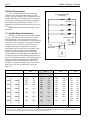
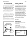
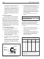
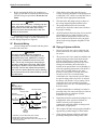
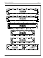
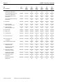
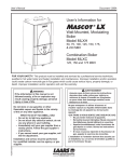
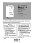
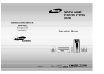
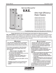
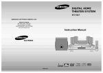
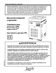
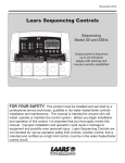
Installation and Operation Instructions
Document 1065D
Installation and Operation
Instructions for
Mighty Therm
Model HH
Sizes 2000-5000
Hydronic Boilers
FOR YOUR SAFETY: This product must be installed and serviced by a professional service technician,
qualified in hot water heater installation and maintenance. Improper installation and/or operation could
create carbon monoxide gas in flue gases which could cause serious injury, property damage, or death.
Improper installation and/or operation will void the warranty.
WARNING
If the information in this manual is not followed exactly, a fire or explosion may result
causing property damage, personal injury or loss of life.
Do not store or use gasoline or other flammable vapors and liquids in the vicinity of this or
any other appliance.
WHAT TO DO IF YOU SMELL GAS
• Do not try to light any appliance.
• Do not touch any electrical switch; do not use any phone in your building.
• Immediately call your gas supplier from a nearby phone. Follow the gas supplier's
instructions.
• If you cannot reach your gas supplier, call the fire department.
H0147600D
Installation and service must be performed by a qualified installer, service agency, or gas
supplier.
A subsidiary of BRADFORD WHITE Corporation
LAARS Heating Systems
Page 2
TABLE OF CONTENTS
SECTION 1.
General Information
3C.
3D.
1A.
1B.
1C.
1C-1.
SECTION 4.
Maintenance
1C-2.
1D.
Introduction ................................................... 3
Flow Requirements ...................................... 4
Variable Water Flow Systems ...................... 4
A Special Note About 3-Way
Water Valves ................................................ 5
System Pressure Requirements ................... 5
Warning Regarding Chilled
Water Systems ............................................. 5
SECTION 2.
Installation
2A.
2B.
2B-1.
2B-2.
2C.
2D.
2E.
2F.
2G.
2H.
Boiler Placement .......................................... 5
Installation of Indoor Boilers ......................... 6
Combustion Air Supply ................................. 6
Venting ......................................................... 7
Installation of Outdoor Heater ....................... 7
Freeze Protection ......................................... 8
Gas Supply and Piping ................................. 8
Electrical Wiring ............................................ 9
Piping of System to Boiler ............................ 9
Filling Fully-Connected System .................. 10
SECTION 3.
Operation
3A.
3B.
Initial Start Up ............................................. 10
To Start Up System .................................... 11
To Turn Off Boiler ....................................... 12
To Shut Down System ................................ 12
................................................................... 12
SECTION 5.
Troubleshooting and Analysis of
Service Problems
................................................................... 13
SECTION 6.
Conversion of VW from Indoor
to Outdoor Models
................................................................... 15
SECTION 7.
Parts Description and Order Numbers
................................................................... 18
Mighty Therm Hydronic Boiler
SECTION 1.
General Information
IMPORTANT WARNING:
The Model HH hydronic boiler must be installed in
accordance with the procedures outlined in this
manual. Warranty does not apply to boilers not
installed or operated in accordance with these
procedures. Consult local building and safety codes
before proceeding with work. The installation must
conform to the requirements of the authority having
jurisdiction or, in the absence of such requirements,
to the latest edition of the National Fuel Gas Code,
ANSI Z223.1 and/or in Canada, CAN1-B149
requirement.
When required by the authority having
jurisdiction, the installation must conform to
American Society of Mechanical Engineers safety
code for controls and safety devices for automatically
fired boilers No. CSD-1, and in Canada, CGA3.3.
Any modification to the boiler, its gas controls, gas
orifices, wiring or draft diverter may void the Laars
warranty. If field conditions require such
modifications, consult Factory.
Indoor
Page 3
1A. Introduction
This manual provides information for the
installation and operation of Laars boilers. It is
strongly recommended that all application and
installation procedures be reviewed completely before
proceeding with the installation. Consult the factory,
or local factory representative, with any problems or
questions regarding this equipment. Experience has
shown that most operating problems are caused by
improper installation.
Model HH boilers are offered in two
configurations: An indoor version and an outdoor
version. The indoor version is convertible for outdoor
use with the installation of a conversion kit as
described in Section 6 of this manual. The two
configurations are shown in Figure 1.
Some accessory items are shipped in separate
packages. Verify receipt of all packages listed on the
packing slip. Inspect everything for damage
immediately upon delivery, and advise the carrier of
any shortages or damage. Any such claims should be
filed with the carrier. The carrier, not the shipper, is
responsible for shortages and damage to the shipment
whether visible or concealed.
Outdoor
When boiler is ordered with stage or modulated control and sales order states it is to be used on a variable flow system, the
temperature controller is factory installed in the outlet water.
Figure 1. Boiler Configuration.
LAARS Heating Systems
Page 4
1B. Flow Requirements
All low volume hydronic boilers must have
continuous flow through the heat exchanger when
firing, for proper operation. The system pump must be
capable of developing sufficient pressure to overcome
the resistance of the boiler plus the entire circulating
system at the designated GPM (see Table 1). The
temperature rise across the boiler should never exceed
40° F.
NOTE: Water entering boiler should be 105°F
minimum.
Convectors Baseboards
or Fan Coils
Fan Coils
Zone Valves
1C. Variable Water Flow Systems
Heating systems using zone valves, zone pumps
or 3-way valves can experience reduced water flow
through the boiler. This can result in an excessive
water temperature rise and unstable boiler operation. If
system water flow is variable, it must not be allowed
to fall below 30% of full flow. The boiler must be
equipped with staged or modulated fire with the
temperature sensor installed in the outlet water. State
variable flow when ordering. Laars recommends
primary-secondary pumping for all variable flow
systems. Primary-secondary pumping is mandatory for
variable flow systems where minimum flows are less
than 30% of full flow conditions. The boiler pump in a
primary-secondary system maintains constant flow
through the boiler even though the system flow is
variable. In a primary-secondary system the pressure
drop of the boiler is not added to the system (see
Figure 2).
20°F
Compression Tank
Pump
(Location varies
with model)
12"
Max.
System Pump
Unit
Figure 2. Primary-Secondary System.
25°F
30°F
35°F
Size (I)
Size (E)
GPM
H/L
GPM
H/L
GPM
H/L
GPM
H/L
20001P
2P
24501P
2P
30501P
2P
35001P
2P
40501P
2P
45001P
2P
50001P
2P
----------22001P
2P
28001P
2P
32001P
1P
36001P
2P
40001P
2P
45001P
2P
164
164
201
201
250
*
284
*
332
*
369
*
410
*
3.91
10.5
5.9
16.4
9.3
*
12.0
*
17.2
*
21.75
*
27.0
*
131
131
161
161
200
200
230
*
266
*
295
*
328
*
3.6
7.4
3.9
10.2
5.9
16.4
8.7
*
11.9
*
13.2
*
16.8
*
109
109
134
134
167
167
189
189
222
222
246
*
273
*
1.8
4.9
3.8
7.7
4.5
12.5
5.7
16.8
8.1
24.0
10.0
*
13.0
*
94
94
115
115
143
143
164
164
190
190
211
211
234
*
0.7
3.0
2.3
5.7
3.8
8.5
3.9
10.5
5.8
16.0
7.0
20.0
9.0
*
HIGH
NORMAL
LOW
* Not recommended, consult factory.
I=Indoor, E=Outdoor. GPM=Water flow. H/H=Pressure drop (head loss)through the boiler, expressed in Ft. of H20. 1P=Single-pass heat exchanger.
2P=Two-pass heat exchanger. Shaded area is the recommended flow and temperature rise.
Table 1. Water Flow, Temperature Rise and Pressure Drop.
Mighty Therm Hydronic Boiler
Page 5
1C-1. A Special Note About 3-Way
Water Valves
3-way water valves (2 position or proportional)
are sometimes used to divert water around a boiler and
control the temperature of water being supplied to the
system. Valves installed in this manner must be
supplied with an end switch or some other suitable
control to shut off the boiler when the flow is reduced
to 30%. The boiler must be supplied with staged or
modulated fire as indicated in Section 1C, Variable
Water Flow Systems.
It is often possible to accomplish excellent water
temperature control without 3-way valves through
proper application of staged or modulated firing
systems. Consult the factory or local Laars
representative for assistance with such systems.
1C-2. System Pressure Requirements
The Model HH boilers are designed to operate
on closed, pressurized systems. A minimum of 12 psi
should be maintained on the system where boiler
supply water temperatures are 200°F or less. If higher
temperatures are required, the minimum system
pressure should be at least 15 psi above the water
vapor pressure corresponding to the elevated water
temperature.
The Model HH boilers are not suitable for
open systems unless the supply water temperatures are
kept below 180°F, and a minimum of 5 psi static head
is maintained at the boiler.
1D. Warning Regarding Chilled
Water Systems
When a boiler is connected to an air conditioning
system where the same water is used for heating and
cooling, chilled water must be prevented from entering
the boiler. When changing such a system from cooling
to heating, the chilled water should be allowed to
circulate through the building after the chiller has been
turned off long enough for the water to warm up to at
least 70°F before the water is allowed to flow into the
boiler. It is equally important to prevent hot water
from entering the chiller. The system shown in Figure
3 is suggested to make sure that the system water is
neither too hot nor too cold when a changeover from
heating to cooling, or vice versa, takes place. When a
boiler is connected to heating coils located in air
handling units (where they may be exposed to
refrigerated air circulation), the boiler piping system
shall be equipped with a flow control valve or other
automatic means to prevent gravity circulation of
chilled water through the boiler. Chilled water in the
boiler will create condensate on the boiler tubes which
will drip on the burners and may extinguish the pilot.
Boilers installed in violation of either of the
above requirements may void the warranty.
SECTION 2.
Installation
2A. Boiler Placement
The boiler must be placed to provide clearances
on all sides for maintenance and inspection. There
must also be minimum distances maintained from
combustible surfaces.
All boilers must be installed on a noncombustible floor. Under no circumstances can boilers
be installed on carpeting.
The National Fuel Code allows a boiler to be
placed on a combustible surface when such an
installation complies with the local codes. This code
specifies the surface under the boiler be protected with
hollow masonry no less than 4" thick, covered with
sheet metal at least 20 Ga. in thickness. Such masonry
Suggested Wiring Diagram For
Tempering System Water at
Changeover from Heating to Cooling
Clock Timer
Auto-resetting
Set at 15 minute SPDT
DPDT Manual or Automatic
Change-over Switch
DPDT - Set at Change-over
Temperature
115/24V
Transformer
From
Chiller
To Boiler
and
Chiller
Valve Motors
2-Pos
3-Wire - 24V
By-pass
From
Boiler
From
System
To
System
3-Way Valve No. 1
Change-over
(Heating and Cooling)
3-Way Valve No. 2
To By-pass
Both Heater and
Chiller
Figure 3. Boiler-Chiller Installation.
Clearance
From
Top
Water Connection Side
Opposite Side
Front
Rear
Vent
Indoor
(Inches)
Outdoor
(Inches)
24
24
24
48
24
6
—
24
24
48
24
—
Table 2. Minimum Clearances from Combusible Surfaces.
LAARS Heating Systems
Page 6
must be laid with ends unsealed, and joints matched
in such a way as to provide a free circulation of air
from side to side through the masonry (see Figure 4).
2B. Installation of Indoor Boilers
1.
2.
2B-1. Combustion Air Supply
The boiler location must provide sufficient air
supply for proper combustion, and ventilation
of the surrounding area as outlined in the latest
edition of ANSI standard Z223.1, and/or in
Canada CAN1-B149 requirement, and any local
codes that may be applicable. Inadequate
combustion air supply may result in incomplete
combustion and consequent sooting of the heat
exchanger and unsafe operation of the boiler.
In general, in the U.S., these requirements
specify that boiler rooms, which represent
confined spaces, should be provided with two
permanent air supply openings communicating
directly through the wall to outside air; one
within 12 inches of the ceiling, the other within
12 inches of the floor. Each opening should
have a minimum free area of one square inch
per 4,000 BTUs/H input rating of all appliances
in the enclosed area. See Table 3 for
recommended air supply for each model. An
improperly ventilated equipment room can get
excessively hot and cause accelerated
deterioration of controls and electrical
components.
Base Must Extend Out
Min. 12" On All Sides
Of Heater Frame
Metal Plate 20
Ga. Min.
Under Entire
Heater
NOTE: In Canada (Table 3 does not apply)
consult local building and safety codes or, in the
absence of such requirements, follow CGA
requirement, and/or CAN1-B149 standard.
3. Exhaust Fans or Vents: Any equipment which
exhausts air from the boiler room can deplete the
combustion air supply or reverse the natural draft
action of the venting system. This could cause
flue products to accumulate in the boiler room.
Additional air must be supplied to compensate
for such exhaust. The information in Table 3 is
not applicable in installations where exhaust fans
or blowers of any type are used. Such
installations must be designed by qualified
engineers.
4. If a blower or fan is used to supply air to the
boiler room, the installer should make sure it
does not create drafts which could cause
nuisance shutdowns of the pilot. If a blower is
necessary to provide adequate combustion air to
the boiler, a suitable switch or equivalent must
be wired into the boiler control circuit to prevent
the boiler from firing unless the blower is
operating.
5. The boiler must be completely isolated and
protected from any source of corrosive chemical
fumes such as emitted by trichlorethylene,
perchlorethylene, chlorine, etc.
Indoor
Size
Each Opening*
(Square Inches)
2000
2450
3050
3500
4050
4500
5000
500
613
763
875
1013
1125
1250
Net Free Area in Square Inches*
Concrete Blocks Or Tile
Min. 7" High With 3" Min.
Air Openings
Blocks must provide solid base and be braced so
they cannot slip out of place. Air openings in blocks
must be arranged to provide unobstructed opening
through entire width or length of base.
Figure 4. Non-combustible Base.
*Area indicated is for one of two openings;
one at floor level and one at the ceiling, so
the total net free area would be double the
figures indicated. For all other conditions,
refer to latest edition of ANSI Bulletin
Z223.1.
NOTE: Check with louver manufacturers for Net Free
Area of louvers. Correct for screen resistance to the
Net Free Area if a screen is installed. Check all local
codes applicable to combustion air.
Table 3. Minimum Recomended
Air Supply To Boiler Room.
Mighty Therm Hydronic Boiler
1.
2B-2. Venting
Laars boilers have built-in draft diverters for
natural draft operation and must not be
connected into any portion of a mechanical draft
system under positive pressure. The flue outlet
must be connected to a clear, unobstructed vent
of adequate capacity terminating above the
highest point of the building with an approved
vent cap. The venting system should be installed
according to the latest edition of ANSI Z223.1
and any local codes having jurisdiction and/or in
Canada follow CAN1-B149 standard.
IMPORTANT NOTE: Do not use sheet metal
screws at the snap lock joints of Type B gas vents.
2.
3.
4.
Do not weld or fasten the vent pipe to the boiler
draft hood. The weight of the stack must not rest
on the boiler. The draft hood and boiler top must
be easily removable for normal boiler service
and inspection.
Avoid long horizontal runs of the vent pipe, and
too many 90° elbows, reductions and restrictions.
Horizontal runs should have at least a ¼" rise per
foot in the direction of flow. A vent connector
shall be supported for the design and weight of
the material employed to maintain clearances and
prevent physical damage and separation of joints.
Avoid terminating boiler vents near air
conditioning or air supply fans. The fans can
pick up exhaust flue products from the boiler and
return them inside the building, creating a
possible health hazard. A minimum of 4 feet
horizontal distance must be maintained from
electric meters, gas meters, and relief equipment.
Page 7
5.
6.
7.
Always use double-wall or insulated vent pipe
(Type B or equivalent). In cold weather,
uninsulated outside vents can chill the rising flue
products, blocking the natural draft action of the
venting system. This can create a health hazard
by spilling flue products into the boiler room.
Avoid oversize vent piping or extremely long
runs of the pipe which may cause excessive
cooling and condensation. Rule of Thumb: The
total length of the vent, including the connector
and any offset, should not exceed 15 feet for
every inch of vent diameter. Longer total lengths
shown in venting tables are based on maximum
capacity, not condensation factors.
When the installation of a draft fan is necessary
in the venting system to which a Laars boiler is
to be connected, the installation should be
engineered by competent personnel following
good engineering practices. The draft fan
supplier should be consulted for correct size. The
installation should be in accordance with the
latest edition of ANSI Z223.1 and any local
codes having jurisdiction, in Canada follow
CAN1-B149 standard. When a draft fan is
installed, a suitable draft switch must be used
and wired into the boiler control circuit at
terminal designated “Field Interlock,” to prevent
firing of the boiler unless a positive draft has
been established (see Figure 5).
2C. Installation of Outdoor Boilers
Caution
Outdoor installations are not recommended in areas
where the danger of snow blockage exists.
1.
2.
Locate the boiler to provide the minimum
clearances as listed in Section 2A, “Placement of
Boiler.”
Do not locate the boiler in an enclosure or wall
recess. Avoid location where wind deflection off
structures might cause down draft. When such
Window
Or Grill
G
N
RO
W
Indoor
Room
Figure 7. Method of Installing a Tee Sediment Trap.
Figure 6. Incorrect Outdoor Installation of Boiler.
LAARS Heating Systems
Page 8
3.
wind conditions are possible, locate the boiler
at least three (3) feet from the structures.
Never install the boiler under any kind of roof
overhang. Do not locate the boiler below or
adjacent to any doors, windows, louvers, grills,
etc. which communicate in any way with an
inhabited area of a building. Even though such
communication might be through another
structure such as a garage or utility room (see
Figure 6).
4.
5.
The boiler and its individual shutoff valve must
be disconnected from the gas supply piping
system during any pressure testing of that system
at test pressures in excess of ½ psig. The boiler
must be isolated from the gas supply piping
system by closing its individual manual gas
shutoff valve during any pressure testing of the
gas supply piping system at test pressures equal
to or less than ½ psig.
Provide gas supply pressure to the boiler as
follows:
2D. Freeze Protection
Natural Gas
LPG
Boiler installations are not recommended in
areas where the danger of freezing exists unless
proper precautions are made for freeze protection.
Maintaining a mixture of 50% water and 50%
ethylene glycol is the preferred method of freeze
protection for hydronic systems. This mixture will
protect the boiler to temperatures of about -35°F. To
get the desired temperature rise across the boiler
when this mixture is used, increase the G.P.M. flow
recommended for water by 15%. Increase the head
loss requirement by 20%.
Note: The boiler and all other gas appliances
sharing the boiler gas supply line must be firing at
maximum capacity to properly measure the inlet
supply pressure. Low gas pressure could be an
indication of an undersize gas meter and/or obstructed
gas supply line.
2E. Gas Supply and Piping
6.
Review the following instructions before
proceeding with the installation.
1. Verify that the boiler is fitted for the proper
type of gas by checking the rating plate. Laars
boilers are normally equipped to operate below
a 2000 foot altitude. Boilers equipped to
operate at higher altitudes have appropriate
stickers or tags attached.
2. Use the figures in Table 4 to provide adequate
gas piping (check local code for BTU capacity
required).
3. A trap (drip leg) must be provided ahead of the
gas controls (see Figure 7). Where required by
code, provide a second manual gas shutoff
valve. Do not remove manual valve furnished
with the boiler.
Gas Supply
Inlet
To
Equipment
Inlet
Tee
Fitting
Nipple
3" Min.
Min. (inches water column)
Max.(inches water column)
7.
7
9
11
14
The correct burner manifold gas pressure is
stamped on the rating plate. The regulator is preset at the factory, and normally requires no
further adjustment.
The gas manifold and control assembly was
tested and conform to the safe lighting and other
performance criteria specified in the latest
editions of ANSI Z21.13 and CGA 3.3 Low
Pressure Boiler Standard.
Distance from Gas Meter or Last Stage Regulator
Indoor
Size
Outdoor
Size
0-100'
Nat. Pro.
100-200'
Nat. Pro.
200-300'
Nat. Pro.
2000
------
2½
2
3
2½
3
3
2450
2200
3
2½
3
2½
3½
3
3050
2800
3
2½
3½
3
3½
3
3500
3200
3
2½
3½
3
4
3½
4050
3600
3½
3
4
3½
4
3½
4500
4000
3½
3
4
3½
5
4
5000
4500
4
3½
4
3½
5
4
NOTES:
These figures are based on 1/2" water column pressure drop.
Cap
Check supply pressure and local code requirements before
proceeding with work.
Pipe fittings must be considered when determining gas pipe sizing.
Figure 7. Method of Installing a Tee Sediment Trap.
Mighty Therm Hydronic Boiler
8.
Page 9
Before operating the boiler, the complete gas
supply system and all connections must be tested
for leaks using a soap solution. Do not use raw
flame.
Caution
Since some leak test solutions, including soap and
water, may cause corrosion or stress cracking, the
piping must be rinsed with water after testing,
unless it has been determined that the leak test
solution is noncorrosive.
1.
Check boiler wiring and pump for correct
voltage, frequency and phase. If the pump circuit
is other than 115V, check to see that the boiler is
provided with an appropriate transformer.
2.
Wire the boiler and pump exactly as shown in
the wiring diagram supplied with the boiler.
3.
The pump and boiler must be electrically
interlocked so the boiler cannot come on unless
the pump is running.
4.
All field installed electrical safety devices and all
field installed devices (draft switches, relays,
timers, outdoor temperature reset devices, etc.)
can be connected to the boiler wiring at points
shown in the wiring diagram designated “Field
Interlock.”
Arrangement of gas train components for on-off,
2-stage and 4-stage firing are shown schematically in
the Gas Piping Diagram (see Figure 8).
2F. Electrical Wiring
(electrical diagrams are included with the packet
provided with each unit)
WARNING
The boiler must be electrically grounded in
accordance with the most recent edition of the
National Electrical Code, ANSI/NFPA 70 and, in
Canada, follow Canadian Electrical Code CSA
C22.1. Do not rely on the gas or water piping to
ground the metal parts of the boiler. Many times,
plastic pipe or dielectric unions isolate the boiler
electrically. Service and maintenance personnel
who work on or around the boiler may be standing
on wet floors and could be electrocuted by a poorly
grounded boiler.
Note:
Main Gas Valves
Incorporate Gas
Pressure Regulators
Pilot Gas Valve**
2G. Piping of System to Boiler
1.
Be sure to provide gate valves at the inlet and
outlet to the boiler so it can be readily isolated
for service.
2.
The pressure relief valve must be installed in the
tapped opening provided in the boiler header
with its outlet piped to a drain or floor sink.
Special attention must be given to relief valve
settings in installations where the boiler is
located on the ground floor of a tall building, or
where the operating temperature of the boiler is
above 210°F. In both instances, the static
pressure of the system is elevated, and could
cause the relief valve to leak and bring
considerable raw water into the system. Where
no special setting of the relief valve is ordered,
the factory will furnish a 125 psi setting. Never
reduce the relief valve opening. If necessary,
install the relief valve in a Tee immediately past
the boiler outlet.
3.
A boiler installed above radiation level must be
provided with a low water cutoff device either as
part of the boiler or at the time of boiler
installation (see Figure 9).
4.
Install manual and/or automatic bleeding devices
at high points in the system to eliminate air.
Install a correctly sized expansion or
compression tank with suitable air charger and
tank drainer, as appropriate.
5.
The weight of all water and gas piping should be
supported by suitable hangers or floor stands.
6.
Check piping diagrams with local applicable
plumbing, heating and building safety codes.
Pilot Gas Filter
Pilot Gas
Pressure Regulators
To Pilot
Pilot Gas Valve**
To Pilot
B
Manual Pilot
Gas Valve
Main Gas Valve†
A
Manual
Gas
Valve
Safety
Solenoid
Valve(s)
To Main
Burners
Hi-Pressure
Switch*
Main Gas Valve†
To Main
Burners
* Standard on sizes 3050-5000 (AGA models).
** Sizes 2000 & 2450 use one pilot gas valve.
† Sizes 2000, 2450 & 3050 with on-off or two stage fire, use
one main gas valve.
LAARS Heating Systems
Page 10
2H. Filling Fully-Connected System
1.
Close all bleeding devices and open make-up
water valve. Allow system to fill slowly.
2.
If make-up water pump is employed, adjust
pressure switch on pumping system to provide a
minimum of 12 psi at the highest point in the
heating loop.
3.
4.
If a water pressure regulator is provided on the
make-up water line, adjust the pressure regulator
to provide at least 12 psi at the highest point in
the heating loop.
Open bleeding devices on all radiation units at
the high points in the piping throughout the
system, unless automatic air bleeders are
provided at such points.
5.
Run system circulating pump for a minimum of
30 minutes with the boiler shut off.
6.
Open all strainers in the circulating system and
check for debris.
7.
Recheck all air bleeders as described in Step 4.
Check liquid level in expansion tank. With the
system full of water and under normal operating
pressure, the level of water in the expansion tank
should not exceed ¼ of the total, with the
balance filled with air.
9.
Start up boiler according to procedure described
in Section 3A. Operate the entire system,
including the pump, boiler, and radiation units
for one (1) hour.
10. Recheck the water level in the expansion tank. If
the water level exceeds ¼ of the volume of the
expansion tank, open the tank drainer and drain
to that level.
11. Shut down the entire system and vent all
radiation units and high points in the system
piping as described in Step 4.
12. Close make-up water valve and check strainer in
pressure reducing valve for sediment or debris
from the make-up water line. Reopen make-up
water valve.
13. Check gauge for correct water pressure and also
check water level in the system. If the height
indicated above the boiler insures that water is at
the highest point in the circulating loop, then the
system is ready for operation.
14. Within three (3) days of start-up, recheck all air
bleeders and expansion tank as described in
Steps 4 and 8.
Air Changer
and Tank
Drainer
Make-up
Water
Supply
Compression
Tank
Check
Valve
Method 2
To Drain
Pressure
Reducing
Valve
8.
SECTION 3.
Operation
3A. Initial Start Up
Method 1
Blow Down
Valve
To
Drain
To System
Strainer
Pump
Thermometer
Temperature
and Pressure
Gauge
Lighting: Safe lighting and other performance
criteria were met with the gas manifold and control
assembly provided on the boiler when it underwent
tests specified in the ANSI Z21.13 standard.
Before placing the boiler in operation, the
automatic safety shutoff devices must be checked.
Once the boiler is connected to the gas piping and
after all of the requirements in Section 2 have been
met, follow this procedure:
1.
Before beginning the tests, make sure the main
manual gas valve, and any other boiler firing
valves, are in the OFF position.
2.
Make sure the power switch on the boiler is in
the “ON” position. After placing the manual
pilot valves in the open position, and resetting all
safety devices (high limit, pressure switch, low
water cutoff, etc.), pilots can be lit following the
procedure located on the boiler rating plate.
Notes: Select Method 1 or 2 when using Low Water Cutoff
accessory:
1. Under Method 1, the Low Water Cutoff is furnished by Laars and
shipped as a separate item for field installation.
2. Under Method 2, Electronic Low Water Cutoff is installed, wired
and tested on boiler in Laars factory.
3. Preferred location of system pump is shown. Compression tank
must always be on suction side of pump.
Figure 9. Boiler Piping.
Mighty Therm Hydronic Boiler
3.
Once the pilots are lit and have been established
for five minutes, the flame failure response time
should be checked as follows:
System 16: (Electronically supervised standing
pilot system standard on propane gas) Extinguish the
pilot flame by placing the manual pilot valve in the
closed position, and, at the same time, begin recording
the time it takes for the output signal from the
electronic ignition control to be interrupted. Refer to
the electrical drawing supplied with the boiler for
wiring details. The signal interruption can be detected
either with a test light or a voltmeter. Because the
ignition controls are in series, the control just
upstream of the gas valves should be tested first.
Under no circumstances should the response time
exceed 5 seconds.
System 18: (Intermittent ignition supplied only
for natural gas) With this system, pilots are
automatically lit when the thermostat calls for heat.
The pilots are permitted a trial period for ignition, then
the system is locked out if it fails to light. To retry
ignition, power to the boiler must be momentarily
interrupted. After the pilot is initially lit, the trial for
ignition time should be checked by turning off pilot
gas, and, at the same time, monitoring the time it takes
for the audible sparking at the pilot burner to stop.
Under no circumstances should the trial for ignition
exceed 15 seconds. Because the electronic ignition
controls are in series, the control just upstream of the
gas valves should be tested first (refer to the electrical
drawing supplied with the boiler).
Once the trial for ignition period has been
checked, the controls should be reset and the flame
failure response time checked by following the
procedure given for system 16.
4.
With the pilots lit, initial activation of the main
burners can be achieved by slowly opening the
main manual valve. The result should be a
smooth lighting of the main burners.
Hi-Limit Checkout
After running the boiler for a long enough period
to bring the water temperature within the range of the
hi-limit, slowly back off the high limit setting until the
boiler shuts off. The main burners should reignite
when the hi-limit is turned back up to its original
setting.
The high limit should now be reset and the boiler
run until it shuts off automatically on high limit.
Now that all tests of the safety shutoff devices
have been completed, refer to Section 3B for the
proper settings of temperature controls.
Page 11
3B. To Start Up System
(See Section 3A for Initial Startup)
1.
Start up boiler:
a. Be certain system pump is running.
b. Lighting instructions are provided on the
boiler rating plate and in the User’s Manual
and are as follows:
1.
Turn off main electrical switch.
2.
Turn off all manual gas valves and wait five
minutes.
3.
Set aquastat or thermostat to lowest setting.
4.
Slowly turn manual gas valve to ON.
5.
Reset all safety valves (pressure switch and
manual reset high limit).
6.
Open manual pilot valve. Turn on main electrical
switch.
7.
Set temperature controller to desired
temperature. Pilot will light automatically to
ignite main burners whenever the thermostat
calls for heat.
8.
The low firing rate setting must be equal to or
greater than the specified minimum input rating
as shown on the appliance rating plate. For
example, size 2450 has a specified minimum
input of 735,000 BTUs/hr. The unit's input rate
must not be below this value (refer to rating
plate). Laars boilers use gas valves which are
factory set to provide an input on low fire that
meet or exceed the specified minimum.
2.
Set temperature controls:
Boilers on constant flow will have the
temperature controller bulb located in the boiler inlet
and the high limit sensing bulb in the boiler outlet.
Boilers on variable flow will have both the
temperature control sensing bulb and the high limit
sensing bulb located in the boiler outlet.
When boiler is installed on a constant water
flow system, set temperature controller at the designed
system supply temperature less the temperature drop
in the system. Set the high limit switch 30°F above the
supply temperature to the system.
When boiler is equipped with staged or
modulated
fire and installed on a variable flow system, set
temperature controller at the designated system
temperature. Set the high limit switch 30°F above the
supply temperature to the system.
LAARS Heating Systems
Page 12
3C. To Turn Off Boiler
1.
Turn off main electrical switch.
2.
Close all manual gas valves.
3D. To Shut Down System
To shut down boiler, turn off all manual gas
valves and electrical disconnect switch. Whenever
danger of freezing exists, shut off water supply and
remove drain plug in bottom of front header cover and
drain every part of system subject to freezing
temperatures.
SECTION 4.
Maintenance
1.
If a strainer is employed in a pressure reducing
valve or in the piping, clean it every six (6)
months.
2.
At start-up and every six (6) months thereafter,
the pilot and main burner flame should be
observed for proper performance (see Figure 9
and 10; see attached lighting and shutdown
instructions for proper pilot flame pattern). If
flame has the appearance of “sooting” tips, check
for debris near orifices. Call service technician.
3.
Inspect the venting system for obstruction,
leakage, and corrosion at least once a year.
4.
Keep boiler area clear and free from combustible
material, gasoline and other flammable liquids
and vapors. Boiler surfaces are hot and could
ignite combustible material.
Pilot (P/N W0034500)
5.
Be certain all combustion air and ventilation
openings are unobstructed.
6.
Check for fouling on the external surfaces of the
heat exchanger every six months.
NOTE: After installation and first start-up,
check the heat exchanger for fouling after the
following periods of operation: 24 hours, 7 days, 30
days, 90 days, and once every six months thereafter.
Fouling on the external surfaces of the heat
exchanger is caused by incomplete combustion, and is
a sign of combustion air and/or venting problems. As
soon as any fouling is observed, the cause of the
fouling should be corrected (see Section 5
Troubleshooting). The heat exchanger can be checked
with a flashlight by locating a mirror under the
burners. An alternate method is to remove the venting
and top panel as necessary to inspect from above.
Also, check the vent system for defects at the same
time.
a.
If cleaning is required, shut off all electrical
and gas supply to the boiler.
b.
To expose the heat exchanger:
Remove top panel covers located at the base of
the front and rear flue collector panels. Remove all but
the top screws on each side of the front and rear flue
collector panels. The panels can be swung outward
and propped up to reveal the heat exchanger. Remove
all heat exchanger baffles.
c.
Remove all burners:
Caution
Black carbon or green soot on a dirty heat
exchanger can, under certain conditions, be ignited
by a random spark or open flame. To prevent this
unlikely occurrence, dampen the soot deposits with
a wet brush or fine water spray before servicing or
cleaning the heat exchanger.
C/L 4th Port
Burner
A
Top View
Figure 10. Pilot Location.
Front View of Boiler
Observation Hole
View On
Arrow A
Figure 11. Periodic Flame Observation.
Burner
Mighty Therm Hydronic Boiler
Page 13
With a wire brush, remove soot and loose scale
from the heat exchanger. Do not use water or
compressed air for cleaning. Clean fallen debris from
the bottom of the boiler. Check that burner ports are
clear and pilot assembly is free of debris.
d.
7.
b.
c.
Reassemble in reverse order:
Be sure to replace the heat exchanger
baffles.
The gas and electric controls installed on the
boilers are designed for both dependable
operation and long life. But the safety of this
equipment depends completely on their proper
functioning. It is strongly recommended that the
basic items be checked by a competent service
technician every year, and replaced when
necessary. The basic controls are:
2.
Electric meter(s) with the following ranges:
0 to 500 volts A.C.
0 to 1000 ohms continuity.
Millivolt meter with the following ranges:
0 to 50 millivolts.
0 to 500 millivolts.
0 to 1000 millivolts.
d.
Tube cleaning kit consisting of reamer,
stainless steel brush, speed handle and
handle extensions.
e.
Boiler thermometer (with 1/2" NPT well)
100-240°F.
In addition, the boiler should be equipped with a
system pressure gauge and a thermometer with
proper ranges for boiler operation.
a. Water temperature controls.
b. Pilot safety system.
c. Automatic electric gas valve(s).
d. Flow sensing safety device (when used).
8.
Both modulating and staged valves are adjusted
at the factory for minimum permissible rates, and
should not be readjusted.
SECTION 5.
Troubleshooting and Analysis of
Service Problems
1.
Possible Cause
For proper service and problem diagnosis of the
boiler and boiler system, the following tools are
required:
a.
Gas pressure test kit with range from zero
to 14" W.C. Either a slack tub manometer
or an accurate gas pressure gauge is
acceptable with proper adaptors which will
connect to the available fittings in the line
and on the gas valve.
What To Do
A. Electric power is off.
A. Check to see that main power.
switch is “ON.” Use testing
device to trace power to
heater junction box.
B. Operating or safety control
has opened circuit to
electric gas valve.
B. Turn off power. Use continuity
across terminals of each
operating and safety control
switch up to the electric gas
valve. Replace defective
control.
C. Pilot flame is out.
C. Relight pilot per instruction.
D. Manual reset device has
tripped.
D. Follow instructions for startup. Reset pilot safety and all
manual reset safety switches
and reset manual safety gas
valve.
E. No gas pressure to burners.
E. Trace gas line to service
shutoff cock. If service cock is
open, trace gas line to meter.
If no pressure is present at
meter, call for public utility
service. If gas is present in
boiler inlet, check pressures in
following sequence:
(1) downstream from pressure
regulator. (2) downstream
from electric gas valve.
Replace or adjust as
necessary.
Low water cutoffs should be inspected every six
(6) months, including flushing or float types.
NOTE: Warranty does not cover any damage
caused by lack of required maintenance or improper
operating practices.
9.
3. Boiler will not fire.
F. Electric gas valve operator is F. Disconnect wiring harness at
burned out or shortened.
gas valve terminals. Check
continuity to actuator coil. If
open circuit or short is
indicated, replace coil or
operator.
LAARS Heating Systems
Page 14
4. Boiler is pounding, Knocking or emitting steam
from relief valves.
Possible Cause
A. Low or no water flow.
What To Do
A.This condition is usually caused
by lack of adequate water flow
through boiler.
Check the following:
1. Is the heater wired into the
pump circuit so that the boiler
cannot fire unless the pump is
running?
2. Check to see that all valves
in system are open to be sure
that water can circulate through
the boiler and the system.
3. If the system has automatic
water valves (2-way or 3-way)
that can cut off the water flow
through the boiler check to see
that they are equipped with
end-switches which shut the
boiler down when the water
flow through the boiler is
reduced by 70% from full flow.
Also be sure that manual
bypasses are provided around
two-way zone valves where
necessary in order to assure
15% of full flow through the
boiler at all times.
4. Examine pump for clogged
impeller
5. Water flow through the
system may be impeded by air
locks at high points. Residual
oil in system tends to collect at
high points and clog automatic
air vents. Be sure that all high
points are adequately vented.
B. Low or no system pressure
B.Check for inoperative water
makeup valve or pump. Also
clean strainer in pressure
reducing valve which furnishes
makeup water. Look for closed
valve in makeup water line or a
leak in the system.
C. Clogged “Y” strainer.
C.Remove strainer element and
clean screen.
D. Debris from system piping is D.Remove header covers.
blocking tubes.
Examine all tubes and
waterways. Use new gaskets
when reassembling.
Clean out tubes.
E. Scale has formed in tubes.
E.This is always caused by the
inflow of raw water into the
system. Check for leak in
system, especially at pump
packing. Check for waterlogged expansion tank. This
condition will cause water to
discharge through the relief
valve every time the boiler fires
and permits raw water to enter
the system every time it cools
down. Drain expansion tank.
5. Pressure relief valves leaking intermittently or
steadily.
Possible Cause
What To Do
A. Static pressure in system
A.Calculate height of water in
exceeds setting of relief valve. system above boiler. Install
new valve with psi setting
25% above required static
system working pressure.
Do not exceed 160 psi.
B. Expansion tank is
waterlogged.
B.Drain expansion tank, then
reopen it to the system. Look
for leaks in expansion tank or
fittings. Calculate required
volume of expansion tank in
relation to system to
determine that tank is
adequate.
C. Valve between system and
expansion tank is closed.
C.Open valve so that pressure
in system will be open to tank.
6. Soot in flueways or in tubes, or noxious fumes
indicative of bad combustion.
Possible Cause
What To Do
A. Combustion air supply to
heater room is inadequate.
A. Check air supply opening.
Look for debris in screen or
louvre which covers
combustion air opening, or for
material blocking the opening.
B. Stack or vent is blocked or
restrictive.
B. Look for blocked stack and
excessive number of elbows in
stack or excessive length of
horizontal runs.
C. Severe down draft is
causing spillage of flue
products into room.
C. Check for (1) proper vent cap
on stack; (2) adequate height
of stack above roof; (3)
equipment exhausting air from
inside of building; and (4)
setting on the barometric
damper if applicable and
(5) proper installation of draft
diverter.
D. Gas pressure to burners is
excessive.
D. Check gas pressure with
manometer, and adjust with
heater firing at full rate.
E. Boiler not fitted for the fuel
being supplied
E. See nameplate for correct
fuel.
F. Boiler installed at high
altitude without proper
derating.
F. Installations at altitudes in
excess of 2000 ft. above sea
level are subject to jurisdiction
of the local inspection
authorities.
G.Water entering boiler is
105°F
G.Add balancing valves if
needed to raise entering
temperature.
Mighty Therm Hydronic Boiler
Page 15
Outdoor Kit Parts List (see Figure 13)
7. Water dripping in firebox.
Possible Cause
What To Do
A. If boiler is used with an air
conditioning system, chilled
water may be flowing either
by gravity or pressure
through boiler and
creating condensation on
boiler tubes.
A.Install flow-check valve or
programmed bypass valve in
the system for change-over
from heating to cooling.
B. Tube in heat exchanger has
overheated and ruptured.
B.A tube failure always caused
by
(a) scale formation in the tube
or
(b) inadequate water flow
through the boiler.
SECTION 6.
Conversion of Series HH Boilers
from Indoor to Outdoor Model
Please read the following instructions with
Figure 12.
Figure 13 shows the conversion completed.
Please follow the instructions in their numerical
order, failure to do this will cause problems on
assembly.
1.
Remove top panel, (1) (see Figure 12).
2.
Remove front and rear upper panels, (2)
(see Figure 12).
3.
Remove front and rear wings LH & RH, (3)
(see Figure 12).
4.
Remove diverter assembly, (4) (see Figure 12).
5.
Remove outer screw from upper end panel at
junction with lower end panel.
Key No.
Part No.
5 ............................................................................. 20017100
6 ............................................................................. 20016900
7 ............................................................................. 20015101
............................................................................... 20015102
8 ............................................................................. 20016700
9 ............................................................................. 20017200
10 ........................................................................... 20017300
11 ........................................................................... 20017700
12 ........................................................................... 20016500
13 ........................................................................... 20016600
14 ........................................................................... 20016300
15 ........................................................................... 20014301
............................................................................... 20014302
16 ........................................................................... 20015200
17A Left Front Baffle (Single Inlet Manifold) ......... 20022200
17B Right Front Baffle (Single Inlet Manifold) ....... 20022300
17C Left Front Baffle (Split Inlet Manifold) ............ 20022000
17D Right Front Baffle (Split Inlet Manifold) ......... 20022100
18 ........................................................................... 20014601
............................................................................... 20014602
19 ........................................................................... 20016100
20 ........................................................................... 20018000
21 ........................................................................... 20016200
22 ........................................................................... 20017200
23 ........................................................................... 20017600
24 ........................................................................... 20018200
25 ........................................................................... 20018300
26 ........................................................................... 20018600
27 ........................................................................... 20015001
............................................................................... 20015002
28 ........................................................................... 20016800
1
2
3
4
Figure 12. Removal of Indoor Parts.
Page 16
Figure 13. Outdoor Parts Identification.
LAARS Heating Systems
Mighty Therm Hydronic Boiler
5.
Remove outer screw from upper end panel at
junction with lower end panel.
6.
Remove and disconnect all probes and wires
going to castings and gas train.
7.
Remove control box assembly - front of boiler
(not shown).
Page 17
12. Install middle rear panel. (13)
13. Install front panel making sure opening for
removable panel is square. (19)
14. Install front stiffener size 2450 and up.
Section 2 (See Figure 13)
1.
2.
Install front LH & RH extension panels (flush
with top of upper end panel), (18).
Install rear LH & RH extension panels (flush
with top of upper end panel). (15) (pick up holes
provided into LB upper and lower end panels)
3.
Install front bottom panel. (21)
4.
Install rear bottom panel. (14)
5.
Install front inner baffles [2] 4" from ends. (17)
6.
Install rear inner baffle [1] 2" from ends. (16)
7.
Install front LH & RH upper spacers. (27)
8.
Install rear LH & RH upper spacers. (7)
9.
Install front flue collector extension (screw onto
flange of lower flue collector only). (28)
10. Install rear flue collector extension (screw onto
flange of lower flue collector only). (8)
11. Install rear upper panel and remaining screws
from flue collector extension. (12)
15. Install remaining screws from flue collector
extension.
16. Install rear top half. (5)
17. Install front top half. (6)
18. Install front wire (26) mesh using angle (24) at
top and strap (25) at bottom (mesh to be
inserted under angles of wind baffle stand offs).
19. Install rear mesh same as Step 18.
20. Install front LH & RH wind baffle stand off. (23)
21. Install rear LH & RH wind baffle stand off. (23)
22. Install front and rear wind baffles. (22)
23. Install middle rear baffle stand off. (11)
24. Install middle rear baffle. (10)
25. Install wires control box parts onto control panel
(not shown).
26. Install control panel assembly using holes and
bushings provided in RH extension panel for
probes and wires (not shown).
27. Install door panels. (20)
LAARS Heating Systems
Page 18
SECTION 7.
Parts Description and Order Numbers
Key
No. Description
Size
2000 I
Size
2450 I
2200 E
Size
3050 I
2800 E
Size
3500 I
3200 E
Size
4050 I
3600 E
Size
4500 I
4000 E
Size
5000 I
4500 E
1.
Base Weldment Assembly
20067201
20067202
20067203
20067204
20067205
20067206
20067207
2.
Base Assembly
20011001
20011002
20011003
20011004
20011005
20011006
20011007
3.
Center Heat Shield Assembly
20005701
20005702
20005703
20005704
20005705
20005706
(2)
20005707
(2)
3a. Center Heat Shield Panel
20005601
20005602
20005603
20005604
20005605
20005606
(2)
20005607
(2)
4.
End Tile Rail Support
Assembly (left)
20011101
20011101
20011101
20011101
20011101
20011101
20011101
4a. End Tile Rail Support
Assembly (right)
20011102
20011102
20011102
20011102
20011102
20011102
20011102
5.
20064301
20064302
20064201
20064202
20064401
20064402
20064501
20064502
20064600
20064600
20064700
20064700
20064800
20064800
6a. Main Burner Assembly
Pilot Burner Bracket
20012600
20012600
20012600
(2)
20012600
(2)
20012600
(2)
20012600
(2)
20012600
(2)
6b. Main Burner (without
pilot bracket)
L2005800
(22)
L2005800
(27)
L2005800
(32)
L2005800
(37)
L2005800
(44)
L2005800
(48)
L2005800
(54)
7.
Inner Shield
20002300
(2)
20002300
(2)
20002300
(2)
20002300
(2)
20002300
(2)
20002300
(2)
20002300
(2)
8.
End Tile Channel
20002600
(2)
20002600
(2)
20002600
(2)
20002600
(2)
20002600
(2)
20002600
(2)
20002600
(2)
9.
Front Lower Closure
20004301
20004302
20004303
20004304
20004305
20004306
20004307
10. Rear Tile Rail Assembly
20011401
20011402
20011403
20011404
20011405
20011406
20011407
11. Front Tile Rail Assembly
20011301
20011302
20011303
20011304
20011305
20011306
20011307
12. Rear Closure Assembly
20012401
20012402
20012403
20012404
20012405
20012406
20012407
13. Heat Shield Support Bracket
20003201
(2)
20003202
(2)
20003203
(2)
20003204
(2)
20003205
(2)
20003206
(2)
20003207
(2)
14. Tile Heat Shield Assembly
20012101
(2)
20012102
(2)
20012103
(2)
20012104
(2)
20012105
(2)
20012106
(2)
20012107
(2)
15. Lower Panel Assembly
F&R
20011601
(2)
20011602
(2)
20011603
(2)
20011604
(2)
20011605
(2)
20011606
(2)
20011607
(2)
16. Tile Cover
20005801
(2)
20005802
(2)
20005803
(2)
20005804
(2)
20005805
(2)
20005806
(2)
20005807
(2)
17. Saddle Assembly End Tile
10533601
(2)
10533601
(2)
10533601
(2)
10533601
(2)
10533601
(2)
10533601
(2)
10533601
(2)
Manifold Assy. Single
Manifold Assy. Split
18-19. Tile Assembly
See Tile Drawing on Page 20
20. Center Support Assembly
20004900
20004900
20004900
20004900
20004900
20004900
20004900
21. Heat Exchanger Assembly
20001301
20001302
20001303
20001304
20001305
20001306
20001307
21a. Gasket, Header
S0095300
S0095300
S0095300
S0095300
S0095300
S0095300
S0095300
21b. Water Barrier
10397500
10397500
10397500
10397500
10397500
10397500
10397500
21c. Double Pass Header
10416200
10416200
10416200
10416200
10416200
10416200
10416200
I=Indoor, E=Outdoor
Quantity is one unless otherwise indicated.
Mighty Therm Hydronic Boiler
Figure 14. Parts Identification.
Page 19
LAARS Heating Systems
Page 20
Key
No. Description
Size
2000 I
Size
2450 I
2200 E
Size
3050 I
2800 E
Size
3500 I
3200 E
Size
4050 I
3600 E
Size
4500 I
4000 E
Size
5000 I
4500 E
21d. Gasket, Flange
S0095600
(2)
S0095600
(2)
S0095600
(2)
S0095600
(2)
S0095600
(2)
S0095600
(2)
S0095600
(2)
21e. Flange
10417400
(2)
10417400
(2)
10417400
(2)
10417400
(2)
10417400
(2)
10417400
(2)
10417400
(2)
21f. Cap Screw-Hex. Hd.
1/2" - 13UNC x 2"
F0024500
(8)
F0024500
(8)
F0024500
(8)
F0024500
(8)
F0024500
(8)
F0024500
(8)
F0024500
(8)
21g. Return Header
10416100
10416100
10416100
10416100
10416100
10416100
10416100
21h. Gasket, Header
S0095300
S0095300
S0095300
S0095300
S0095300
S0095300
S0095300
21j. Cap Screw-Hex. Hd.
1/2" - 13UNC x 1 1/2"
F0013300
(36)
F0013300
(36)
F0013300
(36)
F0013300
(36)
F0013300
(36)
F0013300
(36)
F0013300
(36)
21k. Washer - 1/2"
F0010300
(36)
F0010300
(36)
F0010300
(36)
F0010300
(36)
F0010300
(36)
F0010300
(36)
F0010300
(36)
22. Lock Washer - 3/8"
F0010800
(2)
F0010800
(2)
F0010800
(2)
F0010800
(2)
F0010800
(2)
F0010800
(2)
F0010800
(2)
23. Washer - 3/8"
F0011100
(2)
F0011100
(2)
F0011100
(2)
F0011100
(2)
F0011100
(2)
F0011100
(2)
F0011100
(2)
24. Cap Screw
3/8" - 16UNC x 3/4"
F0015900
(2)
F0015900
(2)
F0015900
(2)
F0015900
(2)
F0015900
(2)
F0015900
(2)
F0015900
(2)
25. Heat Exchanger Baffle Assembly
20010900
(68)
20010900
(68)
20010900
(68)
20010900
(102)
20010900
(102)
20010900
(102)
20010900
(102)
26. Heat Exchanger Baffle F & R
10534310
(2)
10534311
(2)
10534312
(2)
10534313
(2)
10534314
(2)
10534315
(2)
10534316
(2)
27. Front & Rear Closure
20006401
(2)
20006402
(2)
20006403
(2)
20006404
(2)
20006405
(2)
20006406
(2)
20006407
(2)
28. Inside Baffle Assembly Indoor
Inside Baffle Assembly Outdoor
20012501
N/A
20012502
20012509
20012503
20012510
20012504
20012511
20012505
20012512
20012506
20012513
20012507
20012514
29. Flue Panel Assembly
F&R
20011501
(2)
20011502
(2)
20011503
(2)
20011504
(2)
20011505
(2)
20011506
(2)
20011507
(2)
30. Upper Panel
F & R (indoor only)
20011701
(2)
20011702
(2)
20011703
(2)
20011704
(2)
20011705
(2)
20011706
(2)
20011707
(2)
31. Flue Diverter Assembly
(indoor only)
20012201
20012202
20012203
20012204
20012205
20012206
20012207
32. Upper Wing
F & R, Left (indoor only)
20006301
(2)
20006301
(2)
20006301
(2)
20006301
(2)
20006301
(2)
20006301
(2)
20006301
(2)
33. Upper Wing
F & R, Right (indoor only)
20006302
(2)
20006302
(2)
20006302
(2)
20006302
(2)
20006302
(2)
20006302
(2)
20006302
(2)
34. Top Panel Assembly
(indoor only)
20012301
20012302
20012303
20012304
20012305
20012306
20012307
35. Flue End Assembly
20012000
(2)
20012000
(2)
20012000
(2)
20012000
(2)
20012000
(2)
20012000
(2)
20012000
(2)
36. Upper End Assembly
20011900
(2)
20011900
(2)
20011900
(2)
20011900
(2)
20011900
(2)
20011900
(2)
20011900
(2)
37. Lower End Panel Assembly
20011800
(2)
20011800
(2)
20011800
(2)
20011800
(2)
20011800
(2)
20011800
(2)
20011800
(2)
38. Control Mounting Panel
20013700
20013700
20013700
20013700
20013700
20013700
20013700
39. Control Cover - Front
20018700
20018700
20018700
20018700
20018700
20018700
20018700
40. Control Box Cover Top
20011200
20011200
20011200
20011200
20011200
20011200
20011200
I=Indoor, E=Outdoor
Quantity is one unless otherwise indicated.
Mighty Therm Hydronic Boiler
Figure 15. Tile Assembly.
Page 21
LAARS Heating Systems
Page 22
Key
No. Description
Size
2000 I
Size
2450 I
2200 E
Size
3050 I
2800 E
Size
3500 I
3200 E
Size
4050 I
3600 E
Size
4500 I
4000 E
Size
5000 I
4500 E
20035403
20035403
20035403
(2)
20035403
(2)
20035403
(2)
20035403
(2)
20035403
(2)
Pilot Lead Assembly (Honeywell)
Standing Pilot, Nat/Propane
20035404
20035404
20035404
(2)
20035404
(2)
20035404
(2)
20035404
(2)
20035404
(2)
Pilot Lead Assembly (Johson)
IID Pilot, Nat
20035401
20035401
20035401
(2)
20035401
(2)
20035401
(2)
20035401
(2)
20035401
(2)
Pilot Lead Assembly (Honeywell)
IID Pilot, Nat
20035402
20035402
20035402
(2)
20035402
(2)
20035402
(2)
20035402
(2)
20035402
(2)
42. Pilot Shield
20016400
20016400
20016400
(2)
20016400
(2)
20016400
(2)
20016400
(2)
20016400
(2)
43. Draft Hood Relief
Baffle - Right (indoor only)
20013801
(2)
20013801
(2)
20013801
(2)
20013801
(2)
20013802
(2)
20013803
(2)
20013804
(2)
44. Draft Hood Relief
Baffle - Right (indoor only)
20013805
(2)
20013805
(2)
20013805
(2)
20013805
(2)
20013806
(2)
20013807
(2)
20013808
(2)
45. Manual Valve
V0001800
V0001800
V2013800
V2013800
V2013800
V2013900
V2013900
46. Safety Valve
V0046800
V0046800
V0046900
V0046900
V0046900
V2000500
V2000500
47. Operating Valve
V0051400
V0051400
V2001000
V0051400
(2)
V0051400
(2)
V0051400
(2)
V0051400
(2)
48. Manual Pilot Valve
W0002100
W0002100
W0002100
(2)
W0002100
(2)
W0002100
(2)
W0002100
(2)
W0002100
(2)
49(a). Pilot Valve (I.I.D.)
(not shown)
W0019300
W0019300
W0019300
(2)
W0019300
(2)
W0019300
(2)
W0019300
(2)
W0019300
(2)
49(b). Pilot Relay (Standing Pilot)
W003000
W003000
W003000
(2)
W003000
(2)
W003000
(2)
W003000
(2)
W003000
(2)
50. Pilot Burner (Johnson)
Standing Pilot, Nat
W0034700
W0034700
W0034700
(2)
W0034700
(2)
W0034700
(2)
W0034700
(2)
W0034700
(2)
W0034800
W0034800
W0034800
(2)
W0034800
(2)
W0034800
(2)
W0034800
(2)
W0034800
(2)
W0034600
W0034600
W0034600
(2)
W0034600
(2)
W0034600
(2)
W0034600
(2)
W0034600
(2)
W0034400
W0034400
W0034400
(2)
W0034400
(2)
W0034400
(2)
W0034400
(2)
W0034400
(2)
W0034500
W0034500
W0034500
(2)
W0034500
(2)
W0034500
(2)
W0034500
(2)
W0034500
(2)
W0034300
W0034300
W0034300
(2)
W0034300
(2)
W0034300
(2)
W0034300
(2)
W0034300
(2)
41. Pilot Lead Assembly (Johnson)
Standing Pilot, Nat/Propane
Pilot Burner (Honeywell)
Standing Pilot, Nat
51. Pilot Burner (Johnson)
Standing Pilot, Propane
Pilot Burner (Honeywell)
Standing Pilot, Propane
52. Pilot Burner (Johnson)
IID Pilot, Nat
Pilot Burner (Honeywell
IID Pilot, Nat
I=Indoor, E=Outdoor
Quantity is one unless otherwise indicated.
Mighty Therm Hydronic Boiler
Page 23
H0147600D
800.900.9276 • Fax 800.559.1583 (Customer Service, Service Advisors)
20 Industrial Way, Rochester, NH 03867 • 603.335.6300 • Fax 603.335.3355
1869 Sismet Road, Mississauga, Ontario, Canada L4W 1W8 • 905.238.0100 • Fax 905.366.0130
www.Laars.com
Litho in U.S.A. © Laars Heating Systems 0805 Document 1065D