1
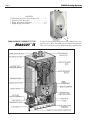
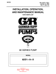
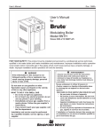
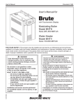
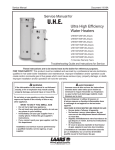
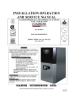
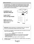
User’s Manual
Document 1239A
User’s Information for
MASCOT ® II
Wall Mounted,
Modulating Boiler
Model LMH
125 MBTU/h
Combination
Boiler and Water Heater
Model LMC
125 MBTU/h
FOR YOUR SAFETY: This product must be installed and serviced by a professional service technician,
qualified in hot water boiler and heater installation and maintenance. Improper installation and/or operation
could create carbon monoxide gas in flue gases which could cause serious injury, property damage, or
death. Improper installation and/or operation will void the warranty.
WARNING
If the information in this manual is not
followed exactly, a fire or explosion may
result causing property damage, personal
injury or loss of life.
Do not store or use gasoline or other
flammable vapors and liquids in the vicinity
of this or any other appliance.
•
•
•
•
WHAT TO DO IF YOU SMELL GAS
Do not try to light any appliance.
Do not touch any electrical switch; do not
use any phone in your building.
Immediately call your gas supplier from a
nearby phone. Follow the gas supplier’s
instructions.
If you cannot reach your gas supplier, call
the fire department.
H2338600A
Installation and service must be performed
by a qualified installer, service agency, or gas
supplier.
AVERTISSEMENT
Assurez-vous de bien suivres les instructions
données dans cette notice pour réduire au
minimum le risque d’incendie ou d’explosion
ou pour éviter tout dommage matériel, toute
blessure ou la mort.
Ne pas entreposer ni utiliser d’essence ni
d’autres vapeurs ou liquides inflammables dans
le voisinage de cet appareil ou de tout autre
appareil.
QUE FAIRE SI VOUS SENTEZ UNE ODEUR DE GAZ:
• Ne pas tenter d’allumer d’appareils.
• Ne touchez à aucun interrupteur. Ne pas vous servir
des téléphones dansle bâtiment où vous êtes.
• Appelez immédiatement votre fournisseur de
gaz depuis un voisin. Suivez les instructions
du fournisseur.
• Si vous ne pouvez rejoindre le fournisseur de
gaz, appelez le sservice des incendies.
L’installation et l’entretien doivent être assurés par
un installateur ou un service d’entretien qualifié ou
par le fournisseur de gaz.
Page 2
LAARS Heating Systems
CONTENTS
Familiarizing yourself to the Laars Mascot II.................2
1. Caring For Your Mascott II.........................................3
2. Filling, Shut Down and Restart................................3-4
3. Digital Display and Control.....................................5-7
FAMILIARIZING YOURSELF TO THE
MASCOT II
®
Figure 2. Location of Components.
To open the front panels. Remove these two phillips screws, and
fold lower door down. The middle panel will then also fold down.
This will reveal the four screws that hold the upper panel in place.
User’s Manual - Mascot II Boilers and Water Heaters
1. Caring For Your Mascot II
Your Mascot II will require very little
maintenance. However, as with any fine appliance
there are certain steps that should be taken to ensure
continuing optimum performance.
1.1 General Care
Keep the area around the Mascot II clean and
free from combustible materials, gasoline and other
flammable liquids and vapors.
The Mascot II must be completely isolated and
protected from any source of corrosive chemical fumes
such as trichlorethylene, perchlorethylene, chlorine,
etc.
Keep bottom and top openings on the boiler free
for proper ventilation of interior components.
Do not obstruct or block a free flow of air to the
boiler to ensure proper ventilation.
If desired, clean the jacket surfaces with a damp
cloth and mild detergent. Do not use flammable
cleaning materials.
If sidewall vented, keep the vent terminal clear
of obstructions — do not pile snow against the vent
terminal. Clean the intake screen often, and then
develop an appropriate maintenance schedule.
1.2 Annual Inspection of Flue and Vents
Visually inspect the vent pipe once a year. Should
any deterioration exist, have the affected parts replaced
by a qualified service person.
1.3 In the Event of a Power Failure
The Mascot II can not be operated during
an electrical power outage. If there is an extended
power outage with danger from freezing, then the
Mascot II (and all other water systems) should be
drained completely. When draining the boiler, turn
off main electrical disconnect switch. When placing
back in service, refer to Section 2 of this Manual for
instruction. All draining and filling must only be done
by a qualified service person.
1.4 Full Service Every Three (3) Years
In addition to the annual visual inspections, a
qualified service agency should conduct a detailed
inspection of all flue product carrying areas of the
boiler and its venting system.
Page 3
2. Filling, Shut Down and Restart
2.1 Filling the Boiler System
1.
2.
3.
4.
5.
6.
Ensure the system is fully connected. Close all
bleeding devices and open make-up water valve.
Allow system to fill slowly.
Move manual lever on 3-way valve actuator to
“open” position, allowing air to purge from boiler
loop. Valve is normally in DHW position until
there is a call for Central Heat via “T-T” contacts.
If a water pressure regulator is provided on the
make-up water line, adjust the pressure regulator
to provide at least 12 psi (81.8 kPa) at the highest
point in the heating loop.
Open bleeding devices on all radiation units at the
high points in the piping throughout the system,
unless automatic air bleeders are provided at such
points.
Note that there is an air bleed located on the left
side of Mascot II, on top of the jacket.
Cycle the boiler pump on and off 10 times, 10
seconds on and 10 seconds off to remove all air
from the heat exchanger. Then run system and
appliance pump for a minimum of 30 minutes with
the gas shut off.
Using manual lever located on left side of 3-way
valve actuator, move from “open” position back to
closed position repeatedly. This process forces air
out of the internal DHW loop.
WARNING
Failure to remove all air from the heat exchanger could
lead to property damage, severe injury or death.
7.
8.
Recheck all air bleeders as described in Step 4.
Shut down the entire system and vent all radiation
units and high points in the system piping, as
described in Step 4.
9. Close make-up water valve and check strainer in
pressure reducing valve for sediment or debris from
the make-up water line. Reopen make-up water
valve.
10. Check gauge for correct water pressure and then
the system is ready for operation.
11. Refer to local codes and the make-up water valve
manufacturer’s instructions as to whether the
make-up water valve should be left open or closed.
12. After placing the unit in operation, the ignition
system safety shutoff device must be tested.
Page 4
Shut off the manual gas valve, and call the unit for
heat. Main gas valve will be energized, attempting
to light, for four (4) seconds, and then will deenergize. The unit will go into lockout after the
required number of trial for ignition periods.
Press the manual reset button on the boiler control,
or the user display, open the manual gas valve and
allow the unit to light. While the unit is operating,
close the manual gas valve and ensure that power to
the main gas valve has been cut.
13. Within three (3) days of start-up, recheck all air
bleeders and the expansion tank as described in
Steps 4 and 8 above.
WARNING
Improper adjustment may lead to poor combustion
quality, increasing the amount of carbon monoxide
produced. Excessive carbon monoxide levels may
lead to personal injury or death.
LAARS Heating Systems
2.2 Shutting Down Mascot II
1.
2.
3.
This step to be performed by a qualified service person.
2.3 To Restart Mascot II
1.
2.
3.
4.
5.
6.
7.
8.
WARNING
Do not use this boiler if any part has been under
water. Immediately call a qualified service technician
to inspect the boiler and to replace any part of the
control system and any gas control which has been
under water.
WARNING
Should overheating occur or the gas supply fail to
shut off, do not turn off or disconnect the electrical
supply to the pump. Instead, shut off the gas supply
at a location external to the boiler.
FOR SERVICE
Contact your installing contractor, gas utility, Laars
dealer, or call Laars for the nearest authorized
representative in your area.
Turn off the main electrical disconnect switch.
Close all manual gas valves.
If freezing is anticipated, drain Mascot II and be
sure to also protect building piping from freezing.
All water must be removed from heat exchanger
and condensate trap or else damage from freezing
may occur.
I f drained, please refer back to section 2.1 of
this manual before restarting.
Turn off the main electrical disconnect switch.
Close all manual gas valves.
WAIT FIVE (5) MINUTES.
Set the aquastat or thermostat to its lowest setting.
Open all manual gas valves.
Reset all safety switches (pressure switch, manual
reset high limit, etc.).
Switch on electrical power.
Burner will go through a prepurge period and
ignitor warm-up period, followed by ignition.
Page 5
User’s Manual - Mascot II Boilers and Water Heaters
3. Digital Display and Control
MENU ITEM
3.1 Digital Display Navigation
The Digital Display is centered in the middle
of the User Interface and has 3 seperate modes of
control. They are USER, SETUP and DIAGNOSTIC.
The names of these modes gives you an idea of the
levels of control. A USER might be the homeowner or
a service technician. SETUP displays all the controls
needed when setting up or expanding the boiler. And
DIAGNOSTIC is intended for a Mascot ll trained
technician. Please view Table 1, Table 2, and Table 3.
USER Mode is the home screen shown on the
control. If the display is not in USER Mode wait for the
display timeout period to be reached or press the Done
button to return to the USER Mode.
SETUP Mode is accessed by holding the up and
down arrow keys simultaneously for 3 seconds.
DIAGNOSTIC Mode can be activated by a trained
Mascot II technician.
Once in a particular menu structure, navigation
consists of pressing the next button to scroll from item
to item and then pressing the up and down arrows to
change values. Once the value is adjusted, the NEXT or
DONE button can be pressed.
DEFAULT
—
—
Delta T
—
—
DHW
The Mascot II has an integrated electronic control
that replaces many of the individual component controls
found on older appliances. The control acts as the
ignition control, pump control, high limit and cascading/
lead lag control and more. All of these functions and
setups are managed through the Digital Display.
RANGE
Inlet water Displays the current inlet
temperature water temperature
Figure 3. The User Interface.
FUNCTION
Outlet water Displays the current outlet 55-180°F 120°F
temperature water temperature & allows
the setpoint to be adjusted
Displays the current temperature rise across
the heat exchanger
Domestic Hot Water
Caution
Stack
Displays the current stack
temperature temperature
—
Outdoor
Displays the current outdoor
temperature air temperature
—
—
Firing Rate
—
—
Displays an indicator of the current firing rate based
upon fan RPM. The actual
firing rate may vary.
—
Table 1. USER Mode Menu.
Caution
Scalding Risk: Laars recommends
the use of a thermostatic mixing
valve at domestic hot water
outlet (boiler location) to
reduce potential for scalding.
The following thermostatic mixing
valve model has been tested and
approved for Mascot II application: Honeywell AM100US-1. Contact Laars for additional recommended models.
MENU ITEM
DEFINITION
F or C Selects temperature units
LBTHODLOD Outdoor reset enable/disable enables menu items
LBT
Low boiler setpoint during outdoor reset
HOD
High outdoor temperature setpoint
LOD
Low outdoor temperature setpoint
RMT Add
Used for Lead/Lag (follow menus)
LL
Lead/Lag enable/disable - enables menu items
HS
Hysteresis - temp range between on/off cycles
bL
Base Load % - input rate before next boiler fires
Sd
Warm weather shut-down temperature
ASC
Anti short cycle - minutes of delay between startup
bAC
Future use - Press DONE to exit menu.
PAS
Future use - Press DONE to exit menu.
NOTE: When enabling/disabling functions, select "Done" and wait 30 seconds before scrolling.
Table 2. SETUP Mode Parameters.
MENU ITEM
DESCRIPTION
Please view your Install/Operating Manual
Table 3. DIAGNOSTIC Mode Menu.
Page 6
3.2 Ignition Control- Sequence of Events
1.
2.
3.
4.
5.
Call for heat
Safety chain check
Fan starts.
Prepurge timer is started.
Pre ignition time of 2 seconds to check the flame
sensor operation and status.
6. Trial for ignition period, 4 seconds. The direct
spark ignition switches to constant spark for three
seconds, during which time the gas valve is open.
For the last second of the ignition period direct
spark is de-energized and the flame sensor checks
for established flame. If flame is sensed the control
enters “Run” to satisfy the demand. If flame is
not established the control enters a retry, starting
from step 2. If flame has not been established in
the appropriate number of retries the control will
lockout with a 109 error code.
7. Call for heat complete
8. Gas valve off
9. Fan and pump over run times active to purge the
system
The sequence is the same for DHW or Central
Heat modes. Upon a call for Central Heat, the 3-way
valve will shift position, allowing boiler water to enter
the building’s heating loop. Only after the value shifts
position will the firing sequence begin.
3.3 Modulation Control
The control uses a PID algorithm to adjust
the firing rate of the boiler as the control point is
approached. The goal of the control is to operate
at a minimum firing rate to match the load on the
appliance. The burner modulates to achieve the setpoint
temperature, away from the actual off point.
3.4 Pump Control
The boiler pump is active anytime there is a call
for heat applied to the control. When there is a central
heat call supplied the system pump relay is active. If
there is a DHW call supplied while the central heat
call is active the system pump turns off. This happens
because of domestic hot water priority, which forces
the control to satisfy the domestic water demand prior
to the hydronic demand. When the last heat demand is
satisfied the boiler pump enters an overrun time.
LAARS Heating Systems
3.5 High Limit
The control uses a dual thermistor sensor to
monitor the Mascot II’s maximum temperature. The
high limit sensor is installed in the outlet water. A dual
thermistor sensor is used, so that the two temperatures
can be monitored and compared to confirm accuracy.
The control will automatically reduce the firing of the
Mascot II to prevent the high limit from tripping. The
high limit setpoint is not adjustable.
3.6 Stack Temperature
The stack temperature is a dual thermistor sensor
and is limit rated. The control compares each of the
temperature readings to determine accuracy. The stack
sensor is used as a limiting feature to avoid excessive
temperatures in the venting.
3.7 Domestic Hot Water Temperature
The domestic hot water temperature sensor is used
to control DHW temperature. The DHW setpoint can be
adjusted through the USER menu structure.
DHW setpoint is displayed during DHW mode. For
LMH model, an aquastat will be used in lieu of a sensor
to control temperature of an indirect tank.
Caution
Scalding Risk: Laars recommends the use of a
thermostatic mixing valve at domestic hot water
outlet (boiler location) to reduce potential for
scalding.
The following thermostatic mixing valve model has been
tested and approved for Mascot II application: Honeywell
AM100-US-1. Contact Laars for additional recommended
models.
User’s Manual - Mascot II Boilers and Water Heaters
3.8 Lead Lag / Cascading
Lead Lag/Cascading allows multiple boilers
to be connected together and controlled from
one common sensor input. Up to 8 boilers can be
connected together in a single system. To setup Lead/
Lag or cascading operation there are several settings
in the “setup” menu structure that must be adjusted
for the specific installation, each is covered in the
following sections.
3.8.1 Lead Lag Setpoint
The lead lag setpoint is set from the “user”
menu using the “LL” variable. This is the temperature
the boiler is attempting to maintain at the system
sensor. This setting doesn’t control the boiler
outlet temperature, so the water temperature at the
boiler outlet may be much hotter than the system
temperature setpoint. Adjust the LL setpoint to the
desired operating temperature of the system.
3.8.2 Lead Lag Master/Slave Selection
In the SETUP menu structure, the “LL” menu
allows the lead lag system to be turned on and the
boiler to be configured as a master or slave control.
In each lead lag system there can only be one master
control, so proper selection is important to avoid
operating issues. To set the boiler to lead lag “master”
operation the LL menu should be set to “LDR”. To set
the boiler to slave, “SLA” should be selected.
3.8.3 Lead Lag Address
The Lead Lag address must be set for each boiler
connected to the lead lag system. Each boiler must
have a unique address selected for the system to work
properly. Typically, the lead or master boiler should be
set to address one and the remaining boilers should be
set to values 2–8 depending upon how many boilers
are installed in the system.
3.8.4 Lead Lag Hysteresis
The lead lag system uses a hysteresis value set
in the setup menu, called, “HS”. The hysteresis and
setpoint values control the on and off points of the
boiler. If the lead lag setpoint is adjusted to 120°F
with a hysteresis value of 5°F the boiler will turn off
when the water temperature reaches 125°F and will
turn back on when the water temperature reaches
115°F. Set the hysteresis values to match the boiler to
the system operating characteristics. Setting this value
correctly will help reduce the chance of short cycling.
3.8.5 Lead Lag Base Load Setting
The lead lag system uses a base load setting that
is set through the “setup” menu called “bL”. The base
load setting identifies the firing rate that the operating
boiler must achieve before the next boiler in the
system is allowed to operate. The default setting is
50% to avoid short cycling and operating the boilers at
higher, less efficient, firing rates.
Page 7
LAARS Heating Systems
H2338600A
Page 8
800.900.9276 • Fax 800.559.1583 (Customer Service, Service Advisors)
20 Industrial Way, Rochester, NH 03867 • 603.335.6300 • Fax 603.335.3355 (Applications Engineering)
1869 Sismet Road, Mississauga, Ontario, Canada L4W 1W8 • 905.238.0100 • Fax 905.366.0130
www.Laars.com Litho in U.S.A. © Laars Heating Systems 1212 Document 1239A