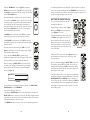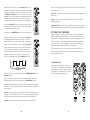
1
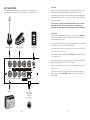
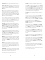
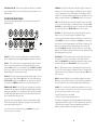
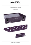
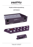
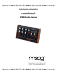
ANALOG
4
D EL A Y
WELCOME TO THE WORLD OF MOOGERFOOGER
ANALOG EFFECTS MODULES!
Your MF-104M Analog Delay is a rugged, professional-quality instrument,
designed to be at home on stage or in the studio. Its great sound and jawdropping effects come from state-of-the-art analog circuitry, designed
and handcrafted by our team at Moog Music in Asheville, North Carolina.
SHORT
LONG
The MF-104M is rooted in the analog wizardry of Bob Moog’s Moogerfooger designs. It is a direct descendent of the original Moog® modular
synthesizers and professional rack effects.
Housed in a rugged steel and hardwood enclosure, your MF-104M
Analog Delay features an all-analog signal path. Its finely-tuned frequency
response and overload contours produce the sound quality of the best
vintage delay devices.
T IM E
The MF-104M Delay Line incorporates a dual-range Bucket Brigade
Device (BBD) providing a range of delay times from 40 milliseconds to
800 milliseconds. A multi-waveform Low Frequency Oscillator (LFO)
enables you to create a variety of effects including chorus, pitch shifting,
and vibrato by modulating the Delay Line.
Several of the performance parameters are voltage-controllable. This
means you can use expression pedals like the Moog EP2, a MIDI-to-CV
converter or any other source of control voltage, such as Moogerfoogers
to play your MF-104M.
In addition, the front panel rotary controls and switches can be controlled
through the use of MIDI and the LFO can be synced to a MIDI Clock.
While you can use it on the floor like a conventional effects box, your Analog
Delay is much more versatile. Its sound quality and versatility is higher than
most fixed-function “stomp boxes” you may be accustomed to. You will
find that your Analog Delay is a deep electronic musical resource that
offers a very large range of analog sound processing possibilities.
5
GETTING STARTED
Let’s get started by unpacking and setting up your MF-104M. Here are
some simple instructions on how to plug in and try your new MF-104M.
Unpacking
1. Remove your new Moogerfooger from the packaging and allow it a few
moments to get its land legs after the long journey to its new home.
2. Inside the box you’ll find your Analog Delay, AC adapter, warranty card,
and this manual. Save the box in case you ever need to ship your MF-104M
back to Moog Music.
3. Don’t forget to register your Analog Delay. Why? Moog is constantly
updating its products. The only way to know about an update is by
registering. The easiest way is by visiting: www.moogmusic.com/register
Connecting
1. Connect an instrument cable from your sound source to the AUDIO IN
jack on your MF-104M. You can feed virtually any instrument or line-level
signal through your MF-104M.
2. If you plan on using MIDI, connect a MIDI cable from the out on the MIDI
controller of your choice to the MF-104M’s MIDI IN.
Guitar or Instrument
Power Supply
Expression Pedal
NOTE: The Analog Delay defaults to MIDI Channel one. Make sure your MIDI controller
is transmitting on MIDI Channel one.
3. Connect an instrument cable from the MIX OUT jack to a line-level input
on your amp or mixer.
4. Using the supplied power adapter, plug the cord into the +9V jack. Then,
plug the power adapter itself into a wall receptacle.
NOTE: The MF-104M requires a power supply of +9VDC, CENTER POSITIVE, rated for
AUDIO IN
MIX OUT
FEEDBACK
DELAY OUT
TIME
LFO RATE
LFO AMT
FB INSERT
Amplifier
MIX
+9V
400 mA
at least 400mA.
5. Once the power supply is plugged in your Moogerfooger is ready to
work. You’ll notice that the BYPASS indicator is red. This indicates the
effect is OFF.
MIDI IN
MIDI Out from
Computer, MIDI
Controller or
Drum Machine
4
5
THE MF-104M FRONT PANEL
LFO CONTROLS (RIGHT PANEL):
The FRONT PANEL of the MF-104M Analog Delay contains the
performance controls and LED indicators.
MF-104M
ANALOG DELAY
LFO RATE - Adjusts the LFO rate from 0.05 Hz to 50 Hz (wider range
available via control voltages and MIDI).
LFO AMOUNT - Controls the amount of LFO modulation of the delay time.
.3
.2
LFO - Six-position rotary switch selects the LFO wave shape for delay
time modulation. Select from Sine, Triangle, Square, Ramp, Sawtooth, and
Sample and Hold modulation.
NOTE: More details on these controls can be found on page 17.
.6
.1
SHORT
THE MF-104M BACK PANEL
The BACK PANEL has all the connection points for sending audio signals in
and out, control voltage inputs, MIDI input, and power supply connector.
LONG
AUDIO IN
FEEDBACK
TIME
LFO RATE
MIX OUT
DELAY OUT
FB INSERT
LFO AMT
MIX
+9V
400 mA
TIME
TAP TEMPO
MIDI IN
AUDIO IN - 1/4” TS jack. Accepts any instrument level to line level
audio signal.
DELAY LINE CONTROLS (LEFT PANEL):
TIME - Adjusts delay times from 40ms to 400ms in Short mode and 80ms
to 800ms in Long mode.
RANGE - Selects between Short and Long delay times and bright or dark
filter. The Short setting is brighter while the Long setting is darker.
FEEDBACK - Provides continuous control from no feedback to greater
than infinite. NOTE: Feedback settings above 8 can cause the unit to self-oscillate.
LEVEL CONTROLS (CENTER PANEL):
DRIVE - Allows 35 dB of adjustment of the input signal for optimum signal
path, level matching and overdriving sound sources.
MIX OUT - 1/4” TS jack. Adjustable output level for instrument or line
level output.
DELAY OUT - 1/4” TS jack. Supplies wet-only output.
FEEDBACK, TIME, LFO RATE, MIX, LFO AMOUNT - All are 1/4” TRS
jacks that accept Moogerfooger EP-2 (or equivalent) expression pedals,
or 0-5VDC control voltages from either two-circuit (TS) or three-circuit
(TRS) 1/4” jacks.
FEEDBACK INSERT - Supplies line-level send and return via a 1/4” TRS jack
for inserting effects into the feedback loop of the Delay line
MIDI IN - Accepts a 5-pin DIN input for controlling the MF-104M via MIDI.
OUTPUT - Allows gain and attenuation of output signal for compatibility
with a wide range of input devices.
+9VDC POWER JACK - Accepts standard 9 volt center positive barrel
power adaptor (power adaptor included). 400mA minimum required.
MIX - Crossfader control for blending wet and dry signals to the output.
NOTE: More details on these connections can be found on page 20.
6
7
SETTING LEVELS
DIGGING IN
1. Turn your amp or monitor on, then, turn its volume control
down but not off.
As you already know by now the MF-104M has a Delay Line and a LFO.
To demonstrate how they work we’ll first check out the Delay Line with
the LFO off. Next, we’ll go over the LFO with the Delay Line at the
minimum setting. Then, we’ll put them together to create some magic.
2. On the MF-104M, turn all controls except the MIX and
OUTPUT LEVEL to their far left position. Turn the MIX knob to
12:00 and the OUTPUT LEVEL to 9:00 as shown in Figure 1.
NOTE: It only seems like magic. In actuality it’s some serious know how on the part
of Moog’s product design team.
3. Press the BYPASS switch so the BYPASS LED turns green
(Figure 2). This means the effect is ON. If you press and hold
the BYPASS switch, you’ll see the LED change from red to
orange or green. Orange or green indicate that the effect
is on but in different modes. For now we’ll focus on Normal.
FIGURE 1
•NORMAL MODE – Green LED
•SPILLOVER MODE – Orange LED
•OFF – Red LED
control to add some distortion.
FIGURE 2
6. Play your instrument or source again. Then adjust the
OUTPUT LEVEL control until the overall volume with the
effect on and with the effect bypassed is the same. You may
have to switch the effect off and on a few times and make
small adjustments. Once you find the sweet spot keep those
knobs set to maximize fidelity and signal-to-noise ratio.
FIGURE 3
Adjust the settings again as shown in Figure 5 and start
jamming. There’s that slapback again but the delayed sound
is darker (has less treble). Now increase the FEEDBACK to 5.
Play while listening to the echoes and you’ll really notice the
difference, even if your ears are a little cooked from a recent
overdose of decibels.
Your Analog Delay was designed with an area of overlap in
the SHORT and LONG delay ranges, with the SHORT range
having a higher frequency response. This provides the ability
to fine tune the tonal characteristics of the delayed sound
(see Figure 6).
If you really need some instant gratification skip to page 13
SHORT
.6
LONG
1
FIGURE 4
.3
.2
.1
.2
SHORT
.6
LONG
1
FIGURE 5
for some great setups.
SHORT (3.0 KHz)
LONG (1.7 KHz)
40
80
400
800 msec
FIGURE 6
8
.3
As you increase the FEEDBACK more of the delayed
signal gets sent back through the Bucket Brigade Device
which means a longer series of repeats.
Note: Red indicates clipping - this is OK if you want to use the Drive
Since we know you are eager to start hearing what your Analog
Delay can do, let’s dig in, learn a little, and hear how the Delay
Line and LFO work together to create some amazing sounds.
.3
.2
.1
Adjust the Delay Line settings as shown in Figure 4 then
play your instrument. That’s the classic “slapback” echo.
Now increase the FEEDBACK control to 5 and play your
instrument again. You’ll hear a fast series of decaying echoes.
4. While playing your instrument (or signal source) turn the
DRIVE control clockwise as in Figure 3 until the LEVEL
LED stays green with occasional orange flashes on peaks.
5. Tap the BYPASS switch until the BYPASS indicator is red.
This means the effect is OFF (bypassed).
GETTING TO KNOW THE DELAY LINE
As you go through this section, adjust controls as shown in
the illustrations on the right side of the page to hear how different Delay Line settings affect the audio output.
9
Adjust the FEEDBACK as shown in Figure 7, and tap the
BYPASS switch to turn the effect OFF. Then press and hold
the BYPASS switch until the LED turns orange. The MF-104M
is now in SPILLOVER mode.
the delayed signal back into the Delay Line. With the control set to about
8, the echoes sustain indefinitely. With the FEEDBACK control set above 8,
the echoes build up chaotically into some amazing electronic textures that
can be both edgy and blurry at the same time.
7
Play your instrument to build up some echoes in the Delay
Line. Now tap the BYPASS switch to turn the effect off while
continuing to play. The signal from your instrument will not
be sent through the effect but any audio currently in the
circuit will continue to sound as if the effect were on. Pressing
and holding the BYPASS button for two seconds toggles
your Analog Delay between modes.
•In NORMAL mode, turning the effect OFF shuts off audio
from the Delay Line. Any new signals bypass the effect.
GETTING TO KNOW THE LFO
This section demonstrates how the LFO
modulates the Delay Line.
Adjust all Delay controls as shown in Figure
10. Press the BYPASS control to bypass the
effect (BYPASS LED = Red).
FIGURE 7
•In SPILLOVER mode, turning the effect OFF allows audio
currently in the Delay Line to continue while any new signals
bypass the effect.
.3
.2
Play your instrument while turning the TIME control as in
Figure 8. You’ll hear the pitch of the delayed signal change
briefly and then return to pitch.
As you change the DELAY TIME the signal becomes
stretched or compressed as it goes through the delay circuit,
thereby speeding up or slowing down the vibrations.
When you change the DELAY TIME you are changing the
clock rate of an oscillator that determines how fast signals
go through the individual circuits in the Bucket Brigade
Device (see Figure 9).
Play your instrument for a few seconds. Tap
the BYPASS switch again to turn the effect
back on and play some more. Hear the difference? This is due to the fact that with the
effect on the Delay Line is still in the circuit
and is creating a very short (40 millisecond)
echo of the signal.
.1
0
SHORT
.6
.05
LONG
0
0
FIGURE 10
.6
.1
SHORT
LONG
1
FIGURE 8
DELAY TIME = .2
DELAY TIME = .6
FIGURE 9
Take a little time to experiment with various settings of the DELAY TIME,
SHORT/LONG switch, and FEEDBACK.
Adjust your LFO controls as shown in Figure 11. Play your
instrument and you’ll hear a classic chorus effect. How
does this happen?
We just noted that changing the DELAY TIME changes how
fast signals go through BBD in the Delay Line. And, you’ll
remember that changing the TIME will cause pitch shifting
of audio already in the Delay Line due to time compression
and expansion of the signal.
In the MF-104M the LFO is used to modify (or modulate) the
rate at which signals go through the BBD based on the chosen
WAVEFORM, RATE, and AMOUNT. In this example of a
chorus effect, the LFO is smoothly modulating the TIME with
a slowly changing sine wave of low amplitude (small peaks
and troughs). Because the sine wave is “gentle”, only minor
pitch shifting occurs.
Here are some things you will notice:
•Changing the SHORT/LONG switch position either halves or doubles the
DELAY TIME and thus compresses or stretches the delayed signal currently
in the Delay Line by a factor of two. This results in the pitch of the delayed
signal being shifted up or down an octave.
•The FEEDBACK control creates the series of echoes by mixing a portion of
10
.3
.2
11
.8
4
FIGURE 11
Adjust the LFO settings as shown in Figure 12. Play your
instrument again and you will hear the delayed signal quickly
sliding up and down an octave, somewhat like a siren. With
the AMOUNT and RATE increased, the sine wave has greater
amplitude and is cycling faster thus modulating the delayed
signal more profoundly. If the pitch change is not quite an
octave you might need to fine tune these settings slightly.
Increase the AMOUNT slowly and, at a setting of around 9,
you will find the point where the pitch of the delayed signal
goes up and down by two octaves.
states. Creates octave and other pitch shifting effects when used to modulate another signal.
•Sawtooth– A wave that very quickly reaches a peak and then ramps down
more slowly.
.8
•Sample And Hold – Also known as a random step, a square-ish wave that
randomly changes from up and down state and wave height (amplitude).
8.0
PUTTING IT ALL TOGETHER
Let’s use another WAVEFORM and check out the differences.
FIGURE 12
Adjust the settings on your MF-104M as shown in Figure 13.
The delayed signal will bounce up and down one octave
without sliding, or for you more classical types, with no glissando. In theory, a square wave has no slope (See Figure 14).
It goes directly from peak to trough to peak without transition. Thus there is no sliding of the pitch. But in practice
there is a brief transition phase which creates odd harmonics
and adds a definite edge or crispness to the tone. If the
octave is not quite right, fine tune the AMOUNT slightly.
.4
8.0
LFO
TIME • • • • • • • •
••• •• ••
•Ramp– A type of sawtooth wave that ramps up slowly to a peak then
drops down quickly.
FIGURE 13
FIGURE 14
Take a few minutes to experiment with different WAVEFORM, RATE, and
AMOUNT settings.
Having the ability to combine your instrument or source signal with a
delayed signal that is also modulated is one way in which the MF-104M
stands apart. The following four setups contain some familiar uses of the
Delay Line with the LFO providing an interesting twist. And speaking of
twist, these setups are just begging for some serious knob turning,
expression pedal wiggling, and other creative high jinks.
The front panel controls are referred to as performance controls for a
reason: They are meant to be played. Your MF-104M Analog Delay is a
musical instrument in itself.
1. STRETCHING TAPE
Classic tape style delay with a stretching
effect courtesy of triangle wave modulation.
Try plugging a Moog EP-2 expression pedal
into the Rate CV jack and use it to speed up
or slow down that stretching effect.
.3
.2
.6
.1
SHORT
Since it’s always good to know the waves before you ride, here are some
brief descriptions, listed from left to right on the WAVEFORM control:
•Sine– A periodic wave that smoothly transitions from peak to trough with
no harmonics. Creates vibrato and tremolo effects when used to modulate
another signal.
•Triangle– A periodic wave creates a triangle shape in moving from peak
to trough. Creates similar effects to a sine wave when modulating another
signal but with a sharper tone due to the generation of odd harmonics.
TIME
•Square– A wave that alternates almost instantaneously between two
12
13
LONG
2. VIBROLAY
A spatial vintage style delay with triangle
wave vibrato added to the trails. Try quick
notes or chords combined with held notes.
Use the Rate and Amount knobs to add
different flavor and feel.
.3
.2
.6
.1
SHORT
LONG
4. SQUARE ROOT
Prepare for octave action with this
awesome square wave mod. Each note
will rhythmically jump up and down a full
octave for percussive bliss. Assign Tap
Tempo to the LFO Rate and stomp away.
Note: If the pitch change is not quite an octave
.3
.2
.6
.1
SHORT
LONG
you might need to fine tune these settings slightly.
TIME
3. STAIR STEPPER
This Ramp modulated preset will have notes
working their way through the roof. Play a
note and let the delay do the rest.
Use the Short/Long switch for even more
musical mangling.
TIME
A NOTE ABOUT TAP TEMPO
.3
.2
.6
.1
SHORT
LONG
The TAP TEMPO switch on your Analog Delay can be used to control either
the DELAY TIME or the LFO RATE. To set a tempo, simply tap the switch
at the desired tempo, in quarter notes. After the third tap the MF-104M will
start calculating the tempo and keep the average tempo as you continue
to tap. To start over, wait five seconds and then press the TEMPO switch
three times to set a new tempo. To revert to using the front panel control,
turn either the TIME knob or LFO RATE knob (depending on which tempo
you are setting).
•Pressing and holding the TAP TEMPO control for at least one second
toggles the Tap Tempo function between the LFO RATE and DELAY TIME.
•The LED indicator for the function being controlled by Tap Tempo will
flash green and flash in sync with the chosen tempo.
TIME
SOME HELPFUL TIPS
•You can use the DRIVE control to create some warm analog distortion of
the input if you so choose.
•By using the TAP TEMPO control to tap very slowly or very quickly, you
can set “illegal” tempos that go outside of the designed ranges of the LFO
and BBD. Doing so creates aliasing artifacts that can sound like ring modulation. It isn’t pretty but it can sound very cool. Please use judiciously.
14
15
ABOUT ANALOG DELAYS
THE MF-104M FRONT PANEL
A delay circuit produces a replica of an audio signal a short time after the
original signal is received. If you listen to the original (direct) signal and the
delayed signal together, the delayed signal will sound like an echo of the
direct. To make a whole series of echoes that die out gradually, you feed
the delayed output signal back to the input. You can determine how far
apart the echoes are by adjusting the delay time of the delay circuit, and
you can adjust how fast the echoes die out by adjusting the amount of
feedback from the delay. In addition, you can determine how loud echoes
are by adjusting the mix between the direct signal and the delayed signal.
This section provides more in-depth descriptions of the controls and
indicators on the MF-104M front panel.
During the early 1970s, large-scale semiconductor analog delay circuits
came into being. These are called Bucket Brigade Delay (BBD) chips,
because they function by passing the audio waveform down a chain of
several thousand circuit cells, which is analagous to water being passed by
a bucket brigade to put out a fire. Each cell in the chip introduces a tiny
delay. The total time delay depends on the number of cells and on how
fast the waveform is “clocked”, or moved from one cell to the next.
In the MF-104M, the LFO creates a control voltage that is used to modulate
the time function of the delay. The BBDs in the Delay Line contain 8192
“buckets”. With the time unmodulated the signal spends the same amount
of time in each bucket based on the selected delay time. With the time
modulated by the LFO, the time is no longer constant (or static) and audio
signals already in the buckets get time compressed or stretched. A good
analogy for picturing this is a clock with a sweep hand to show the seconds.
Imagine that you could hold the sweep hand and either slow it down or
speed it up. Yet, when you let it go the sweep hand instantly went to the
correct position on the clock face. In a sense, this is how the LFO
modulates the Delay Line.
In an analog delay the input can be set to saturate gradually, limiting the
maximum signal level and introducing some low level distortion. This actually
enhances the sound quality over what you would have if the MF-104M
produced no distortion whatsoever.
MF-104M
ANALOG DELAY
.3
.2
.6
.1
SHORT
LONG
TIME
TAP TEMPO
DRIVE CONTROL - Sets the input sensitivity of the Analog Delay. This
control is only active when the effect is ON or in SPILLOVER mode. The
available gain runs approximately 35dB. The Analog Delay is designed to
work with instrument to line-level signals.
LEVEL LED - Works in conjunction with the DRIVE control. Red indicates
clipping. Orange flashes indicate the start of overload. Green indicates the
presence of signal at or below the nominal level.
NOTE: For most instruments, the best approach is to set the DRIVE level so the LEVEL
LED stays consistently green with only peaks in the orange. It is okay to drive the Analog Delay into clipping/distortion if that sound is desired. When using an instrument
with a wide dynamic range, you may want to insert a compressor or limiter prior to
the input of the Analog Delay for the best signal-to-noise ratio without clipping.
16
17
OUTPUT LEVEL - Sets the strength of the Analog Delay output at the
MIX OUT and DELAY OUT jacks. This control is only active when the effect
is on or in Spillover mode. The OUTPUT LEVEL control is designed so that
an overall boost, attenuation or zero gain state can be achieved with any
DRIVE setting.
MIX - Sets the ratio of dry (signal as input) to wet (effected) signal. This
control is only active when the effect is on. Set fully counterclockwise it
allows only the dry signal to pass to the MIX output. The full clockwise
position allows only the wet signal to pass to the MIX output. Any position
between the two will blend wet and dry signal to the output. The DELAY
OUT signal is not affected by the MIX control.
Note: If you’re applying a sustained steady pitch to the MF-104M and the MIX control
is set near 12:00, you may find that the direct and delayed signals alternately reinforce
and cancel each other in rapid succession as the DELAY TIME is varied. This is a normal result of mixing a steady pitch with a delayed replica of itself. It is the analogdelay equivalent of “standing waves” in a reverberant room.
DELAY TIME - Sets the length of delay from the BBD Delay Line based
on the SHORT/LONG (Delay Range) switch setting. In SHORT mode, with
AMOUNT set to 0, the delay time changes from approximately 40ms to
400ms nominal. In LONG mode the available span is from approximately
80ms to 800ms nominal. The DELAY TIME is modulated via the LFO to
create various effects.
Since the delay’s internal anti-alias filter must change for the delay time,
the SHORT setting will yield a higher frequency response for the same delay
time as LONG. Switching from SHORT to LONG will reduce the sound in
the “feedback loop” one octave, while switching the other direction will
double the pitch and time of the loop sound.
FEEDBACK - Sets the amount of Delay Line output fed back into the input
of the Bucket Brigade Device. The feedback is variable from off, slapback
or single repeats, to continuous repeats (at about the 3:00 setting). When
turned past 3:00, the FEEDBACK provides for self-oscillation and swelling
delay sounds.
LFO RATE - Sets the frequency of modulation of the Delay Line by the
LFO. The RATE can be varied from .05 Hz to about 50 Hz. The LFO RATE
LED indicates both the RATE and WAVEFORM of the current LFO settings.
The LED is red when the RATE is set from the front panel, green when the
rate is set by the TAP TEMPO switch, and orange when the LFO is synced
to MIDI clock. When synced to MIDI clock, the RATE control is quantized to
select only rhythmic subdivisions of the MIDI clock tempo.
LFO AMOUNT - Sets the overall amount of modulation of the Delay Line
by the LFO.
Note: As the LFO Amount increases, the functional range of the DELAY TIME control
is decreased, so that the maximum and minimum delay times are not exceeded .
BYPASS - Used to turn the effect ON and OFF. When the effect is on the
Bypass LED is green. When the effect is in SPILLOVER mode the BYPASS
LED is orange. When the effect is off the BYPASS LED is red.
TAP TEMPO - Dedicated switch used for setting the DELAY TIME or the
LFO RATE to a musical tempo.
To initiate Tap Tempo control of the DELAY TIME, press the TAP TEMPO
switch three times with the tempo you want (quarter notes). On the third
press, the TIME LED will change to Green, and the DELAY TIME will change
rates to match the timing of the switch presses.
If you continue to press the TAP TEMPO switch, the TIME will be set by a
running average of the time between switch presses. To start over, wait
five seconds and then press the TAP TEMPO switch three times to set a
new tempo.
To revert the unit to front panel control, simply turn the TIME control. The
TIME LED will turn red, and the DELAY TIME will set by the panel control.
To initiate Tap Tempo control of the LFO, press and hold the TAP TEMPO
switch for at least one second. The LFO LED will flash green to show that
the tap tempo is now routed to the LFO and not the DELAY TIME. To
change back, press and hold the TAP TEMPO switch again until the TIME
indicator flashes green.
WARNING: The Analog Delay Feedback control is able to drive the Delay Line into
self-oscillation. This means the Analog Delay is capable of producing sounds without
any audio signal present. Tones produced by self-oscillating feedback may be much
stronger than normal signal levels. Please watch your speakers and ears. Oscillation
When Tap Tempo is routed to the LFO pressing the switch three times or
more will set the LFO rate to match the tap time. Turning the RATE knob
reverts the unit back to front panel control.
typically begins at the 3:00 position.
Note: When either destination (time or LFO) is synchronized to MIDI Clock messages,
LFO WAVEFORM - Selects the LFO waveform for modulation of the Delay
Time. There are six waveforms available: Sine, Triangle, Square, Sawtooth,
Ramp and Sample and Hold (Random Stepped) waveforms.
Tap Tempo is disabled for that destination only.
Note: No modulation will be heard with the LFO AMOUNT set to zero.
18
19
TIME INDICATOR LED - Flashes red to indicate the delay time. It will flash
green to indicate that it is synced to Tap Tempo and orange when it is controlled by MIDI.
THE MF-104M BACK PANEL
This section provides greater detail of the connection points on the MF104M back panel.
FEEDBACK - 1⁄4” TRS jack that can be used with a Moog EP-2 expression
pedal, or a 0V to +5V control voltage on a standard TS cable. A setting of
0 volts or ground allows for no feedback while a 5V setting gives infinite
feedback. To change the feedback amount from zero to infinite via control
voltage or expression pedal, set the FEEDBACK control to 12:00 position.
TIME - 1⁄4” TRS jack that can be used with a Moog EP-2 expression pedal,
or a 0V to +5V control voltage on a standard TS cable. To change the DELAY TIME for a selected range from longest to shortest via control voltage
or expression pedal, set the DELAY TIME control to 12:00 position.
LFO RATE - 1⁄4” TRS jack that can be used with a Moog EP-2 expression
pedal, or a 0V to +5V control voltage on a standard TS cable.
AUDIO IN
FEEDBACK
TIME
LFO RATE
MIX OUT
DELAY OUT
FB INSERT
LFO AMT
MIX
+9V
400 mA
MIDI IN
AUDIO IN - This 1⁄4” jack provides high impedance, unbalanced audio input. The Analog Delay accepts signals ranging from instrument to line level.
MIX OUT - This 1⁄4” jack provides an unbalanced audio output. When the
effect is on, this output carries the dry and wet signal blend set on the
front panel MIX control. The level is determined by the DRIVE and OUTPUT
level controls. When the effect is off, the input signal passes only through
a high-quality buffer on its way to the output.
DELAY OUT - This 1⁄4” jack provides an unbalanced audio output. This is a
wet-only output, in phase with the MIX output. The level is affected by the
OUTPUT LEVEL knob but not the MIX knob. This output can be used as a
second output in STEREO applications or as a feed for phasing effects.
FEEDBACK (FB) INSERT - This 1⁄4” TRS jack is designed to be used with a
standard insert cable to process the BBD feedback signal path separately
from the dry signal path. This is an unbalanced, line level output and input.
The BBD output signal appears at the tip of the jack, and the return to the
device is applied to the ring of the jack.
Because these are line level signals, some means of attenuation or amplification may be required if using devices designed for lower signal levels,
such as typical guitar stomp boxes.
To use an expression pedal to modify the LFO Rate (0.05 Hz to 50 Hz) set
the LFO RATE to 12:00 position. Rotate the LFO RATE knob counterclockwise. With a 0V control voltage applied to the LFO Rate CV input, the LFO
Rate can be reduced to half of the minimum panel rate. (.025 Hz) Now
rotate the LFO RATE control fully Clockwise. With a +5V control voltage
applied to the LFO Rate CV input, the LFO Rate can be increased to double
the maximum panel rate. (100 Hz)
LFO AMOUNT - 1⁄4” TRS jack that can be used with a Moog EP-2 expression pedal, or a 0V to +5V control voltage on a standard TS cable. To
modify the LFO AMOUNT from minimum to maximum via control voltage
or expression pedal, set the LFO AMOUNT control to 12:00 position.
MIX - 1⁄4” TRS jack that can be used with a Moog EP-2 expression pedal,
or a 0V to +5V control voltage on a standard TS cable. To change the Mix
from dry to wet via control voltage or expression pedal set the MIX control
to 12:00 position.
MIDI IN - Standard 5-pin DIN for receiving MIDI messages from another
MIDI device such as a MIDI controller or a sequencer. Refer to the MIDI section of this manual for use of the Analog Delay with other MIDI devices.
POWER - For connecting to the supplied power adapter. Note: Use only the
proper power supply to avoid damage to the device. Make sure your power supply has
the correct Input voltage specifications for your country:
• 120VAC/60 Hz for the US and Canada
• 230VAC/ 50 Hz for Europe and South America
The output of the adapter is +9VDC and the adapter should be capable of
supplying a minimum of 400mA. The +9VDC is applied to the tip (center)
of a barrel connector plug w/ 5.5mm outer diameter and 2.1mm inner
diameter. The barrel (outside) of the plug is the ground (-).
Note: Unlike the classic MF-104SD and MF-104Z, the FEEDBACK insert is placed
before the first delay in the feedback.
20
21
CIRCUIT CONFIGURATION
The figure below is a simplified block diagram of the MF-104M Analog Delay.
A MIDI CC message has both a CC number from 0-127 and a value from
0-127. The CC values that affect panel controls replace the physical setting
of the front panel controls. When the corresponding front panel control
is changed after receiving a MIDI CC message, the value will return to
that panel control. MSB/LSB refers to 14-bit MIDI which uses a pair of CC
messages to obtain higher resolution control. Use the MSB CC numbers to
control these parameters at 7-bit resolution. Note: Moving a panel control while
receiving MIDI CC messages for that same control will result in conflicting values.
THE FOLLOWING CC MESSAGES CORRESPOND TO PANEL CONTROLS:
�
CC NUMBER
PARAMETER
VALUES
7(MSB), 39(LSB)
Output Level
0-16383 (MSB, LSB)
12(MSB), 44(LSB)
Time
0-16383 (MSB, LSB)
13(MSB), 45(LSB)
Feedback
0-16383 (MSB, LSB)
14(MSB), 46(LSB)
Mix
0-16383 (MSB, LSB)
15(MSB), 47(LSB)
LFO Rate
0-16383 (MSB, LSB)
16(MSB), 48(LSB)
LFO Amount
0-16383 (MSB, LSB)
102
LFO Waveform
0-15=Sine, 16-31=Triangle
32-47=Square, 48-63=Saw
64-79=Ramp, 80-95=S&H
96-127=Smooth S&H
86
Range(Fast/Slow)
0=Slow, 64=Fast
(Moves 1 Octave)
80
Bypass on/off
0-63=Bypassed,
64-127=Active
MIDI CONTROL OF THE MF-104M
The following section explains the MIDI implementation of the MF-104M.
For information about what MIDI is and how it works, you can go to the
following web page for tutorials: www.midi.org/aboutmidi/tutorials.php
MIDI CHANNEL
The default MIDI Channel for the MF-104M is Channel one. To change this,
press and hold both the TAP TEMPO and BYPASS switches. While holding
both, send a MIDI Channel mode message to the Analog Delay on the
desired MIDI channel. The TIME LED will flash yellow indicating that the
message has been received. The MF-104M will now only receive MIDI messages on that channel. The current MIDI Input channel is stored in memory
on power down.
Note: MIDI Clock and System Exclusive messages are NOT Channel Mode messages,
THE FOLLOWING CC MESSAGES DO NOT CORRESPOND TO FRONT
PANEL CONTROLS, BUT EXTEND THE ANALOG DELAY’S CAPABILITIES.
CC NUMBER
PARAMETER
VALUES
5(MSB), 37(LSB)
Time Slew Rate
0-16383 (MSB, LSB)
83
Pitch Bend Amount
0 = Off, 16 = 2 Semi
32 = 3 Semi, 48 = 4 Semi
64 = 5 Semi, 80 = 7 Semi
96 = 12 Semi, 112 = 24 Semi
85
Filter Bright/Dark
0-63 = Bright
64-127 = Dark (Only adjusts
filter, does not affect range)
87
Delay Time
Multiplier
0-31=Norm, 32-63=x2
64-95=x4, 96-127=x8
89
Delay Time MIDI
Sync Enable
0-63 = Disabled
64-127 = Enabled
105
LFO Phase Reset
Any Value=Reset
LFO Phase to 0.
107
LFO Clock Divisions
(See Separate table)
and are received by the Analog Delay regardless of the current MIDI Input Channel.
MIDI CONTROL CHANGE (CC) MESSAGES
The settings of the Analog Delay can be controlled by MIDI Control Change
(CC) messages. In addition to the front panel controls, there are a number
of advanced features that can be enabled and edited with CC messages.
22
23
CC NUMBER
PARAMETER
VALUES
108
Enable LFO MIDI
Sync
0-63 = Disabled
64-127 = Enabled
109
Enable LFO Note
Reset
0-63 = Disabled
64-127 = Enabled
110
Enable MIDI Note
Spillover
0-63 = Disabled
64-127 = Enabled
113
MIDI Note Mode
0-41 = Off
42-83 = Absolute
84-127 = Relative
114
MIDI Tap Tempo A
Any CC Value = a tap
115
MIDI Tap Tempo B
(value > 63) = a tap
117
Time/MIDI
LED Select
0-63 = Time LED
64-127 = MIDI LED
119
Enable Mod Wheel
to LFO Amount
0-63 = Disabled
64-127 = Enabled
LFO CLOCK DIVISIONS (CC#71)
CC#71 VALUE
CLOCK DIVISION
CC#71 VALUE
CLOCK DIVISION
0-5
4 Whole
64-69
1/2 T
6-11
3 Whole
70-75
1/4
12-17
2 Whole
76-81
1/8 Dot
18-23
WH + 1/2 Dot
82-87
1/4 T
24-29
WH + 1/2
88-93
1/8
30-34
WH + 1/4
94-98
1/16 Dot
35-40
WH
99-104
1/8 T
41-46
1/2 Dot
105-110
1/16
47-52
WH T
111-116
1/16 T
53-58
1/2
117-122
1/32
59-63
1/4 Dot
123-127
1/32 T
MIDI NOTE MODES
The MF-104M delay time can be controlled from MIDI Note On messages.
When this mode is enabled the unit receives a MIDI “Note On” message.
The “Note ON” number determines the Delay time. The unit responds to
MIDI note numbers 0 to 90. The MIDI Note On Velocity value is ignored.
In Absolute mode each MIDI note corresponds to a delay time value. In
Relative mode, the delay base time is set by the Time knob, external CV,
or Time MIDI CC. MIDI notes higher or lower than C4 will change the delay
24
time to a musical fraction or multiple of the base time (MIDI note 60/C4
does not change the delay time).
Ex: C3 doubles the delay time (and pitches down any audio in the delay line
by an octave) and C5 halves the delay time (pitching any audio in the delay
line up by an octave).
DELAY TIME MULTIPLIER
The Delay Time Multiplier multiplies the delay time by 2, 4 or 8 vastly extending delay time. This feature is for obtaining unusual/lo-fi echo effects.
When the delay time is increased past the default maximum delay time
available on the front panel, the BBD Clock signal will be audible.
MIDI CLOCK SYNC
Both Delay Time and LFO Rate can be synchronized to MIDI System Realtime Clock messages. These messages are 24 ppq messages that can be
sent via MIDI computer sequencers or from drum machines. To enable the
sending of these messages, consult the user manual for your MIDI device.
When the Analog Delay receives MIDI Clock messages, the corresponding
LED turns Orange to indicate that it is synchronized to the MIDI Clock tempo. When the LFO is synchronized to a MIDI Clock tempo, the LFO can be
set to divisions of this tempo. This is either from the front panel LFO Rate
control, or from MIDI CC# 107. Delay Time MIDI sync is enabled via CC# 89.
Note: Delay Time MIDI Clock Sync overrides MIDI Note Mode. If the Delay Time is synchronized to MIDI Clock, then time changes due to MIDI Note Mode are ignored.
MIDI SYSEX MESSAGES
Used for updating or finding out the unit’s firmware version. For more
information about this, refer to user notes with any firmware updates
posted in the Analog Delay section of the Moog Music website.
CONTROL VOLTAGE INPUTS
•All CV input jacks are 1/4” tip-ring-sleeve phone jacks. The sleeve is
grounded and the ring terminals are supplied with +5 volts which is currentlimited. The tip terminals receive the variable voltages from the pedals.
•An expression pedal for use with the MF-104M should contain a 50K Ohm
or lower linear taper potentiometer.
•Applying a varying voltage to a pedal control input jack has the same
effect as turning the corresponding knob. With the panel controls set to
mid-position, a voltage control of about 5 volts is equal to turning the
corresponding knob through its entire range.
•Note that with the Analog Delay, you may use standard TS cables for
control voltages at the same time as Expression pedals.
25
WARRANTY AND SERVICE INFO
LIMITED WARRANTY
Moog Music warrants that its products will be free from defects in materials
and workmanship, and shall conform to specifications current at the time
of shipment, for a period of one year from date of purchase. During the oneyear period, any defective products will be repaired or replaced, at Moog
Music’s option, on a return-to-factory basis. This Warranty covers defects
that Moog Music determines are no fault of the user.
RETURNING YOUR MF-104M FOR REPLACEMENT/REPAIR
You must obtain prior approval and an RMA number from Moog Music before
returning any product to us. Wrap your MF-104M carefully and pack it with
the power adapter in its original carton. The warranty will not be honored
if the product is not properly packed. Send it to Moog Music with transportation and insurance charges paid. A reasonable cost for service, materials
and return freight will be charged to replace materials defective through
the fault of the user, or for which the one year warranty period has expired.
Transportation and insurance charges from Moog Music to your United
States address, of products repaired or replaced under warranty will be
paid by Moog Music.
26
Note: Specifications subject to change without notice.
Moog®, and Moogerfooger® are registered trademarks of Moog Music Inc.
©2012 Moog Music Inc
MOOG MUSIC INC. 160 Broadway St. Asheville, NC 28801
P: (828) 251-0090 E: [email protected] W: www.moogmusic.com