1
ELECTRONIC COLUMN GAUGE
USER’S MANUAL
Issue no. 1: April 2006
A&E GAUGES LTD.
Unit 7
Redbourn Industrial Estate
Redbourn
Herts
AL3 7LG
Tel: +44 (0)1582 794136
Fax: +44 (0)1582 794463
E-mail : [email protected]
Web: www.a-egauges.co.uk
ISO 9001
Registered Firm
International
Accreditation Board
Certificate No. GB2001469
Registration No. 0044/1
CONTENTS
PROBE PROGRAMMING…..…8
INTRODUCTION……….…2
Simple programming
GETTING STARTED.…….3
Multi-gauging
Unpacking
Electrical Connection
OUTPUTS……………..………...9
Quick Start
RS232
Oscillator connection
CONTROLS…………….…4
SK1…………………………….…10
Range Switch
Zero’s
MEMORY MODE (Optional)…..11
Calibration
Application examples………………12
Tolerance
MAINTENANCE……………...…13
Probe Selector Switch
Cleaning
CALIBRATION……………..5
Fuses
Equipment Required
Warranty
Procedure
SPECIFICATION………..………14
Cont.………………………….…..15
SETTING THE PROBES…6
Procedure
TOLERANCE LED’s……….7
Setting Procedure
-1-
Introduction
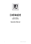
The VC2000 is a single channel vertical column gauge designed for the connection of inductive probes
with the standard Mercer sensitivity. With single or differential measurement options, one or two probes
may be used in any summing or subtracting combination. Units may be inter-connected and probe signals
mixed to provide a multi-channel gauging capability. The measured value is displayed on both the 100
LED bargraph and the 3½ digit red LED numeric display.
Traditional mechanical controls provide for quick and easy set-up and adjustments.
Six metric measuring ranges from ±5.0µm to ±1500µm full scale are selected by rotary switch. Channel
zero adjustment is achieved simply and precisely by turning the recessed rotary control knob. Tolerance
lights are provided for quick ‘Go’, ‘No-Go’ indication.
The 3½ digit numeric display with 0.1µm resolution gives accurate readings for standards room
applications, and its value is output in RS232 format for Data Logging.
A robust steel case gives protection in harsh workshop conditions, and is smartly styled to look good in
the best appointed standards room.
Precision bore gauging is easily achieved by connecting the AE6 Air/Electronic Converter to combine the
simplicity of Air Gauging with the benefits of electronics.
Key Features:
Brilliant, easy-to-read, 100 bar LED display
3½ digit red LED numeric display
Large Red, Green, Amber tolerance indication
Security recessed zero control
6 Metric Ranges - ±5.0µm to ±1.5mm
2 Probe inputs – easy mixing…A, B, A+B, A-B etc.
Resolution 0.1µm
RS232 output … connect to PC
Probe Mixing … inter-connect 2 or more gauges
Wide range input voltage
-2-
Getting Started
Unpacking:
When the VC2000 is first unpacked, the baseplate should be secured to the case as follows:
1) Remove the four screws from the underside of the case.
2) Attach the baseplate with the folded edges down using the same screws.
N.B. The baseplate can accept up to three columns. Mount columns centrally on the baseplate using the
holes provided. Two larger holes are available to mount an AE6 Air/Electronic Converter – in this case mount
the AE6 first, then use the first adjacent holes for the VC2000.
Electrical connection:
The power requirement is ANY voltage between 85 and 260 volts a.c. 48 – 60Hz.
NO VOLTAGE SELECTOR IS NEEDED.
Connect the mains lead and switch on. The green tolerance LED should light and the bargraph should be
somewhere on scale.
Quick start:: - for simple measurement only
Set the range switch to the 50.0µm position. Check the gauge is working by turning the zero control both ways
to make the bargraph move up and down the scale.
If a single probe is to be used, it is usual to use the ‘A’ probe input but the ‘B’ input may be used with equal
validity. Set the probe selector switch to ‘+’.
Set the range switch to the position best suited to the working tolerance of the component. Adjust the probe
mechanically over the master component or reference slip-gauge until the display is near to the correct value.
Trim to the exact size using the zero control.
The equipment is now set up and ready to use.
-3-
Controls
Range Switch - This sets the gauge magnification. The choice of setting is determined by the tolerance
sizes of the component to be measured. The range best suited to the application is likely to give the
expected span of readings over at least 70% of the scale. Avoid using spans close to zero – make the
best use of the scale length.
6 settings are available: ±5.0µm ±15.0µm ±50.0µm ±150.0µm ±500µm ±1500µm
Zero Controls – Channel Zero is a 10 turn control located on the front panel and is recessed to prevent
accidental movement. This control introduces an adjustable offset to the gauge reading.
A and B Probe Zeros are located at the rear and provide offset adjustment to the probe signal. This
control must be used when adjustment is necessary in multi-gauging mode when more than one probe is
being used.
Calibration Controls – Separate A and B controls are located at the rear, and are used to provide fine
adjustment of sensitivity to match the displayed value exactly to the size of the master component.
Tolerance Controls – High and Low setting controls are located on the front panel, and are used to set
the Red/Green and Green/Amber changeover points at the desired scale position.
Probe Selector Switch – A three position switch located at the rear, used to select a Probe input and
determine its polarity. The switch is marked ‘+’ (plus), ‘0’ (neutral), and ‘-‘ (minus). Selecting ‘+’ causes
the gauge to read upward in a positive direction for inward movement of the probe tip. Conversely,
selecting ‘-‘ causes the gauge to read downward in a negative direction for inward movement of the
probe tip.
Plus setting is normally used for external measurements – thickness for example. Use minus settings for
gap or bore measurements.
-4-
Calibration
Equipment Required – It is recommended to use a gauge stand and gauge blocks, but other calibration
standards may be used. A ranging device (calibrated step), drum micrometer or a setting-master device
for use in its gauging fixture is suitable in many cases. Care must always be taken to account for all
sources of error.
When both the ‘A’ and ‘B’ Probe inputs are used together in summing or differential modes, each must
be calibrated independently. Ensure that only the probe to be calibrated is selected by means of its
selector switch. The other selector switch must be in the centre ‘0’ position.
The gauge is supplied factory calibrated to the specification; however periodic verification is advised and
certain procedures require re-calibration. Although the manufacturing tolerance of probe sensitivity is
better than ±1% this may not be sufficiently accurate for some users. The following procedure allows
precise calibration, and therefore a probe should be identified with its own input.
Procedure – Select the range required and set both probe selector switches at the rear to their centre ‘0’
positions. Choose two gauge blocks (slip-gauges) of known precision and place them on the platen of a
suitable gauge stand. For best results, the gauge blocks should span at least 75% of the chosen range.
This example uses the 150.0µm range, but the method used extends to all other ranges. Gauge blocks
200µm (0.200mm) apart in size are chosen.
1) Switch on the gauge and set the display to zero using the front panel zero control.
2) Set the ‘A’ input selector switch at the rear to ‘+’.
3) Set the display to zero using the probe zero control at the rear.
4) Plug the probe into the ‘A’ socket.
5) Fit the probe into the stand over the lower gauge block and mechanically adjust so that the
gauge reads as close as possible to -100.0µm.
6) Set to exactly -100.0µm using the front panel zero control.
7) Move to the higher gauge block and note the new reading. Any error is a deviation from
+100.0µm shown by the display.
8) If adjustment is necessary, note the reading and trim out half the error with the calibration control
at the rear, and the rest of the error with the zero control.
9) Return to the lower gauge block and repeat the procedure if necessary.
The ‘B’ input is calibrated in the same way as above but using the ‘B’ controls.
-5-
Setting the Probes
Where two or more probes are used in combination to measure a single feature, it is necessary for each
probe to be set at its optimum electrical position. Probes should be positioned over a test component or
setting-master to give a zero reading – or some other reading determined by the components actual size.
Procedure :1) Calibrate all probes as described in the ‘Calibration’ section.
2) Connect all probes to their appropriate sockets as defined by the gauge programme.
3) Working in sequence, set the selector switch of the first probe to ‘+’. All other selector switches
must be set to their centre ‘0’ positions.
4) Position the probe in the fixture with the setting-master in place, and lightly clamp when the
display reads approximately zero.
5) Set to exactly zero using the probe zero control at the rear. Do not touch the front panel zero
control at this stage.
6) Repeat this procedure for all other probes, ensuring that all selector switches are at centre ‘0’
position except the one associated with the probe being set. This should be at ‘+’.
7) When all probes have been adjusted, set all selector switches to the polarity defined by the
gauge programme.
8) Finally, using the front panel channel zero control,set the display to read the calibrated value of
the setting-master.
Note: A coarser range switch setting may be used to find the probe position before switching to a finer
range for precision adjustments if this makes things easier.
For single probe applications, set the probe in the fixture with the setting-master in place, and just use
the front panel zero control to make any adjustment.
-6-
Tolerance LED’s
Tolerance limits may be set so that readings outside a given range operate LED signals and additional
logic signals on the rear panel connector SK1. This procedure may be carried out with the probes
disconnected if it is more convenient. All tolerance settings are related to the gauge signal and not
directly to the dimension being measured. This allows the setter to change to a finer range switch setting
to make the zero control cover the desired scale points, if this makes setting easier. All controls must be
restored to the working positions before gauging can be resumed.
Red, Green and Amber LED’s can be set to indicate any out of tolerance condition as follows:
AMBER indicates a plus reading
GREEN indicates within tolerance
RED indicates a minus reading
Note: – following the normal convention, RED indicates a ‘scrap’ condition and AMBER a ‘rectifiable’
condition … this is only valid when gauging external dimensions.
With the Probe Selector Switch set to ‘-‘ (minus) for gauging internal dimensions, the RED LED, for
example, still indicates a minus reading, but a minus bore has plus material and could be rectified.
Setting Procedure - Both controls operate by moving the tolerance point up the scale with clockwise
rotation, and down the scale with anti-clockwise rotation.
1) Initially turn the left, or negative control more than 10 turns anti-clockwise, and the right, or positive
control more than 10 turns clockwise.
2) Using the front panel Zero Control, set the bargraph to the lower tolerance position.
3) Turn the left hand control clockwise until the RED LED just switches on.
4) Check the position by slowly turning the zero control so that the change-over point may be observed.
4) Set the bargraph to the upper tolerance position.
5) Turn the right hand control anti-clockwise until the AMBER LED just switches on.
6) Check the position using the zero control.
Note: if both the amber and red LED’s are lit together, the tolerance controls have been crossed over.
This is easily rectified by turning the controls as described above (1).
-7-
Probe Programming / Mixing
Simple programming - of up to two probes is possible for each column by use of the selector switches
at the rear.
For ratios other than 1:1, ‘self programme’ using the programming connections at SK1 as follows:
Example: 0.5A + 2B
Connect a 10K resistor between SK1 pin9 and pin11
Connect a 2K49 resistor between SK1 pin10 and pin11
Multi-gauging - The gauging of multi-dimensional components frequently entails the combining of outputs
from two or more probes.
The precise combination of outputs, expressed as a formula, will depend on the type of measurement
required e.g. squareness, concentricity, straightness etc.
Programming is achieved through a combination of selector switch settings, and/or linked leads through
SK1 programming connections as follows:
Pin 9
Probe A Out
Pin 11 + Input
Pin 10
Probe B Out
Pin 12 - Input
Note: Probe output is always +ve irrespective of polarity switch setting.
The basis for the calculation of the programming resistor value is:
Ratio 1:1
use 4K99 0.5% Metal Film resistor
Ratio 1:2
use 10K0 0.5% Metal Film resistor
Ratio 2:1
use 2K49 0.5% Metal Film resistor
When the ratio is not a whole number :
To increase sensitivity, divide 5K by the decimal value.
To decrease sensitivity, multiply 5K by the decimal value.
Example :
To increase sensitivity by 1.354 = 5 / 1.354 = 3.69 = resistor 3K69.
To decrease sensitivity by 2.5 = 5 x 2.5 = 12.5 = resistor 12K5.
Note: It may be necessary to combine two resistors in series or parallel to achieve the required value.
-8-
Outputs
RS232 - Transmitted data (TXD) is the value of the 3½ Digit Display exactly as seen with leading zeros
suppressed.
GND
DTR
TXD
RXD
N.C.
5
4
3
2
1
Data transmission is continuous
in the following format:
BAUD RATE = 9600
STOP BITS = 1
START BITS = 8
PARITY = NONE
FLOW CONTROL = NONE
9
N.C.
8
7
6
CTS
RTS
N.C.
Oscillator connection - When two or more units are used together, it is essential to synchronise the
oscillator signals to prevent Probes used in close proximity causing interference to the display.
Link the ‘I’ jack socket from one gauge to the ‘O’ socket of the next for synchronization.
I
O
~
-9-
Outputs - SK1
Analogue Out
1
Analogue 0v
2
Oversize (TTL)
3
Undersize (TTL)
4
Tolerance (TTL)
5
+5v
6
-5v
7
GND
8
9 Probe A Out
10 Probe B Out
11 (Probe) + In
12 (Probe) - In
13 TIR
14 Reset (TIR)
15 Hold (TIR)
Pin 1 = Analogue signal ±1.000 v Full Scale
Pin 2 = Analogue 0v return
Pin 3 = Output goes high when amber LED lights
Pin 4 = Output goes high when red LED lights
Pin 5 = Output goes high when amber or red LED lights
Pin 6 = +5v at 10mA max
Pin 7 = -5v at 10mA max
Pin 8 = Digital ground
Pin 9 = Probe A signal – use for Probe mixing
Pin 10 = Probe B signal – use for Probe mixing
Pin 11 = + input – use for Probe mixing
Pin 12 = - input – use for Probe mixing
Pin 13 = TIR (Optional) – connect to 0v to activate
Pin 14 = Reset – connect to 0v to reset TIR
Pin 15 = Hold – connect to 0v to hold reading (TIR only)
- 10 -
Memory Mode (optional)
The gauge and Probe(s) should be set up in the normal mode before enabling Memory Mode. Refer to
the ‘Calibration’ and ‘Setting the Probes’ sections for the procedures.
Memory mode is activated by connecting SK1 pin 8 to pin 13. This is achieved automatically by
connecting the remote ‘reset/run/hold’ switch box to SK1.
Should the gauge parameters need to be verified at any stage, normal mode is enabled by unplugging
the remote switch box.
Memory options:
HOLD – freezes the display in its position at the moment the switch is operated.
TIR – calculated from (max – min). Biasing the toggle switch to ‘Reset’ sets the display to zero; then by
rotating or moving the part, the gauge memorises the highest and lowest probe deflection, and the
display moves up the scale to indicate the difference between the two values.
Maximum – biasing the toggle switch to ‘Reset’ updates the display to read the current probe position;
then by rotating or moving the part, the gauge memorises the maximum probe deflection and the display
moves up the scale to indicate this value.
Minimum - biasing the toggle switch to ‘Reset’ updates the display to read the current probe position;
then by rotating or moving the part, the gauge memorises the minimum probe deflection and the display
moves down the scale to indicate this value.
Mean – calculated from ½ (max + min). Biasing the toggle switch to ‘Reset’ updates the display to the
current probe position; then by rotating or moving the part, the gauge memorises the highest and lowest
probe deflections and the display moves up and down to indicate half the sum of the highest and the
lowest values.
Note: It is possible that a component being gauged for any feature other than TIR is put into the fixture at
its extreme value. No display change will result from rotation in this case. If this happens it is not a fault
with the gauge – the component should be rotated through 90° and the sequence restarted.
- 11 -
Application examples for different Memory Functions:
HOLD – used to retain a reading at a particular point in a gauging process, or until a feature not to be
gauged has passed the Probe tips.
TIR – simplifies the gauging of run-out, concentricity, parallelism, ovality, taper and face squareness.
e.g. - gives twice the eccentricity of a single diameter of a component rotated on fixed centres under a
single probe. Concentricity of two diameters on a component using two probes in differential (+A – B).
Maximum – used to measure the max. diameter of a component rotated under a single probe, or rotated
about a fixed centre between two diametrical probes. Both applications use probes in the positive mode
(+A, or +A+B).
Minimum – can be used to record the smallest bore size of a component; a bearing outer shell for
example. Use two probes in the minus mode ( – A – B ).
Mean – can be related to the circumference of a (near) circular element. This measure is useful in
gauging a thin ring component that is required to fit into an outer sleeve.
Other options:
Auto Zero – this is not a memory feature as above, but for use in normal mode. The memory circuit is
used to reset the gauge to read zero before the next gauging sequence.
Auto Datum – as for Auto Zero, but the memory circuit is used to reset the gauge to a preset value
determined by the setting of a control.
- 12 -
Maintenance
In general very little maintenance is required. There are no internal, or external components for the user
to service.
Cleaning – when necessary this should be done with a soft, lint free cloth moistened with mild detergent
and water only. Do not apply liquids directly to either front or rear panels as any ingress could cause
electrical failure. Liquids entering the enclosure will invalidate the warranty.
Changing the fuses – the main fuses may blow during use due to power surges etc. Should this occur, it
is important to isolate the incoming power by disconnecting the power lead before any attempt is made
to open the fuse drawer.
To access the fuses, pinch the tabs at each end of the drawer inwards before pulling it out.
Identify which fuse(s) has blown and replace with type T250mA 20 x 5mm.
Warranty
The quality of this instrument is guaranteed for a period of twelve months from the date of delivery. This
guarantee covers all material and manufacturing defects. Liability is confined to repair, or should we
deem it necessary, replacing or crediting the goods.
The following are not covered by the guarantee:
Damage due to incorrect handling or operation.
Failure to observe the operating instructions.
Attempts by any un-authorised personel to open or repair the instrument.
Should you detect an irregularity of any kind, please contact your agent in the first instance.
- 13 -
Specification
Power System:
Display:
Voltage: 85 - 260 V a.c.
Frequency: 48 - 62 Hz
Current: > 0.25A
Fuse: 2 x T250mA 20mm x 5mm.
Bargraph
Numeric
100 bar LED
3½ Digit LED
Resolution:
2% of range
0.1µm / 1µm
Accuracy:
±1Bar or 1% of analogue signal
>0.05% reading ±1 count
Measurement:
Single or Differential
Ranges (µm):
±5.0
Range selection:
6 way rotary switch on front panel.
Zero Adjustment:
Channel: > ±125µm by front panel 10 turn control
±15.0
±50.0
±150.0
±500
±1500
Probe: > ±100µm by rear panel multi-turn control
Calibration:
Each input can be individually calibrated by recessed control at rear
Range: +/-10% of nominal.
Connectors:
Probe: 2 x 5 pin 240º DIN screw retained.
Data: 9 pin ‘D’ socket
SK1: 15 pin ‘D’ socket
Mains: Switched / Fused IEC power inlet.
Probe Inputs:
2 input channels A, B.
Impedance: 10KΩ +/-2%.
Sensitivity: 50mV / V /mm.
Probe Mix:
3 position slide switch on rear panel or any multiple by resistor via SK1
Probe Drive:
Voltage: 1.2V rms, nominal
Frequency: 5.0KHz (no load)
Current: 25mA
- 14 -
Tolerance display:
By LED indication: O/S (amber), SIZE (green), U/S (red).
Setting Range: Any point on scale (no crossover)
Setting Accuracy: < 0.01% full scale, with care.
Outputs:
RS232: via 9 way D socket
Probe signals: via SK1
Analogue: via SK1
Tolerance: via SK1 1 TTL standard load
DC power: +/- 5V at 10mA
Environmental:
Storage: -10°C to +70°C
Working: 0°C to +40°C
Humidity: 10 - 95% non-condensing
Mechanical:
Enclosure: 2mm Mild Steel Painted
Size: 384 h x 130 d x 44 w
Weight: 2.85 Kg
Electromagnetic:
EN61326:1998 Class A
Conformity
EN61010-1:2001
v.1
April 06
- 15 -