1
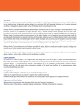
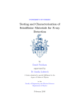
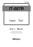
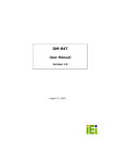
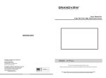
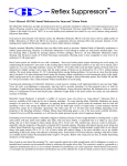
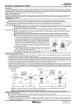
No.99MBH001B1
SERIES No.179
123456789012345678901234567890121234567890123456789012345678901212345678901234567890123456789012
123456789012345678901234567890121234567890123456789012345678901212345678901234567890123456789012
123456789012345678901234567890121234567890123456789012345678901212345678901234567890123456789012
123456789012345678901234567890121234567890123456789012345678901212345678901234567890123456789012
123456789012345678901234567890121234567890123456789012345678901212345678901234567890123456789012
123456789012345678901234567890121234567890123456789012345678901212345678901234567890123456789012
123456789012345678901234567890121234567890123456789012345678901212345678901234567890123456789012
123456789012345678901234567890121234567890123456789012345678901212345678901234567890123456789012
123456789012345678901234567890121234567890123456789012345678901212345678901234567890123456789012
123456789012345678901234567890121234567890123456789012345678901212345678901234567890123456789012
123456789012345678901234567890121234567890123456789012345678901212345678901234567890123456789012
123456789012345678901234567890121234567890123456789012345678901212345678901234567890123456789012
123456789012345678901234567890121234567890123456789012345678901212345678901234567890123456789012
123456789012345678901234567890121234567890123456789012345678901212345678901234567890123456789012
123456789012345678901234567890121234567890123456789012345678901212345678901234567890123456789012
123456789012345678901234567890121234567890123456789012345678901212345678901234567890123456789012
123456789012345678901234567890121234567890123456789012345678901212345678901234567890123456789012
123456789012345678901234567890121234567890123456789012345678901212345678901234567890123456789012
123456789012345678901234567890121234567890123456789012345678901212345678901234567890123456789012
123456789012345678901234567890121234567890123456789012345678901212345678901234567890123456789012
Digi-Derm
Digital coating
thickness gage
User’s Manual
Read this User's Manual thoroughly
before operating the instrument. After reading,
retain it close at hand for future reference.
CONVENTIONS USED IN USER'S MANUAL
Safety Precautions
To operate the instrument correctly and safely, Mitutoyo manuals use various
safety signs (Signal Words and Safety Alert Symbols) to identify and warn
against hazards and potential accidents.
The following signs indicate general warnings:
Indicates an imminently hazardous situation which, if not
avoided, will result in serious injury or death.
DANGER
Indicates a potentially hazardous situation which, if not avoided,
could result in serious injury or death.
CAUTION
Indicates a potentially hazardous situation which, if not avoided,
may result in minor or moderate injury or property damage.
WARNING
The following signs indicate specific warnings or prohibited actions, or
indicate a mandatory action:
Alerts the user to a specific hazardous situation. The given
example means "Caution, risk of electric shock".
Prohibits a specific action. The given example means " Do not
disassemble".
Specifies a required action. The given example means
"Ground".
i
1 INTRODUCTION
CONVENTIONS USED IN USER'S MANUAL
On Various Types of Notes
The following types of notes are provided to help the operator obtain reliable
measurement data through correct instrument operation.
IMPORTANT
NOTE
TIP
• An important note is a type of note that provides information
essential to the completion of a task. You cannot disregard
this note to complete the task.
• An important note is a type of precaution, which if neglected
could result in a loss of data, decreased accuracy or
instrument malfunction/failure.
A note emphasizes or supplements important points of the
main text. A note supplies information that may only apply in
special cases (e.g.. Memory limitations, equipment configurations, or details that apply to specific versions of a program).
A tip is a type of note that helps the user apply the techniques
and procedures described in the text to their specific needs.
It also provides reference information associated with the topic
being discussed.
Mitutoyo assumes no liability to any party for any loss or damage,
direct or indirect, caused by use of this instrument not conforming
to this manual.
Information in this document is subject to change without notice.
© Copyright Mitutoyo Corporation. All rights reserved.
ii
WARRANTY
In the event that the Mitutoyo Digi-Derm should prove defective in workmanship or material, within one year from the date of original purchase for use, it
will be repaired or replaced, at our option, free of charge upon its prepaid
return to us.
This warranty shall not apply if the product has been subject to fair wear and
tear, abuse through misuse or improper use/handling/storage/maintenance/
service/repair or through adaptation/modification by the original purchaser or
any third party without prior written consent of Mitutoyo or as a result of
damage by an actual disaster or circumstances beyond the control of Mitutoyo.
To obtain service under this warranty the product must be returned to the
nearest Mitutoyo Service Center. Any postage, insurance, or shipping charges
incurred in returning the product for service are the responsibility of the
purchaser.
* This warranty is not transferable and is only valid within the country of the
original purchase.
* You may have additional rights under the laws of country of original
purchase that do not allow the exclusion of implied warranties or the
exclusion or limitation of certain damages. If these laws apply, Mitutoyo's
limitations and exclusions may not apply to you.
iii
1 INTRODUCTION
CONTENTS
CONVENTIONS USED IN USER'S MANUAL ......................... i
WARRANTY ........................................................................... iii
1 INTRODUCTION .............................................................. 1-1
1.1 Preface ................................................................................. 1-1
1.2 Application ............................................................................ 1-1
1.3 Nomenclature and Function ................................................. 1-2
2 OPERATION ..................................................................... 2-1
2.1 Setting Power Source ........................................................... 2-1
2.2 Calibration ............................................................................ 2-2
2.2.1 Zero adjustment ..................................................................... 2-2
2.2.2 Gain adjustment .................................................................... 2-3
2.2.3 Notes on calibration .............................................................. 2-4
2.3 Measurement ........................................................................ 2-5
2.3.1 Measurement method ............................................................ 2-5
2.3.2 Holding displayed value ....................................................... 2-6
2.3.3 Outputting displayed value ................................................... 2-6
2.3.4 Rod stand .............................................................................. 2-6
2.3.5 Over indication ...................................................................... 2-6
3 SPECIFICATION AND SAFE-KEEPING .......................... 3-1
3.1 Specifications ....................................................................... 3-1
3.1.1 General specifications ........................................................... 3-1
3.1.2 Output specifications ............................................................ 3-2
3.2 Safe-keeping ........................................................................ 3-4
SERVICE NETWORK
iv
v
1 INTRODUCTION
1
INTRODUCTION
1.1 Preface
The Mitutoyo Digi-Derm is a coating thickness gage of non-destructive
type with a digital display. If it is connected to the Digimatic Miniprocessor, measurements can be printed and processed. Read this operation manual carefully before use.
1.2 Application
1) No.179-741, 179-745 & 179-746
Capable of measuring the thickness of the following types of nonmagnetic plating, films, etc. applied to magnetic materials (Iron,
Nickel, Cobalt, etc.):
• Plating: Gold, Copper, Zinc, Tin, Chromium, Lead, Cadmium, etc.
• Paint: Oil-based paint, Lacquer, Synthetic resin, Metallic-coating,
Rubber paint, etc.
• Lining: Resin, Rubber, Tar, Glass, etc.
• Parkerizing, Metal spraying, Oxide film, and other special film
• Film:Metal, Resin, Rubber, Paper or any other non-magnetic film
can be measured using steel base metal as the reference.
2) No.179-755 & 179-756
Capable of measuring the thickness of the following types of nonconductive plating, films, etc. applied to non-magnetic materials
(Brass, Copper, Aluminum, etc.):
• Paint: Oil-based paint, Lacquer, Synthetic resin, Rubber paint, etc.
• Lining: Resin, Rubber, Tar, Glass, etc.
• Oxide film, and other special film
• Film: Resin, Rubber, Paper or any other non-conductive film can
be measured using Copper, Brass, or Aluminum base metal as the
reference.
MANUAL No. 99MBH001B
1-1
1.3 Nomenclature and Function
1) Main unit
Zero adj. volume
Display
Gain adj. volume
Probe cable
Power sw.
Data output
connector or
Analog output
connector
(179-741)
Inch/mm
conversion
sw.
Hold key
Print key
(except for 179-741)
AC adaptor jack
Battery lid
Rod stand
(Rear view)
1-2
MANUAL No. 99MBH001B
1 INTRODUCTION
2) Probe
Stopper
Cable
Knurled sleeve
Bobbin case
Core
Fig. 1
Zero adj. volume
Used to set the display to zero.
Gain adj. volume
Used to adjust the Digi-Derm to indicate precisely the thickness of
calibration film.
Print key
Used to output the displayed value to the connected Digimatic Miniprocessor. (except for 179-741)
Hold key
Holds and releases the displayed value alternately.
Inch/mm conversion sw.
Converts the displayed mm values to inch values and vice versa.
MANUAL No. 99MBH001B
1-3
1-4
MANUAL No. 99MBH001B
2 OPERATION
2
OPERATION
2.1 Setting Power Source
The Digi-Derm operates from either dry batteries or AC power source.
Perform the following setup with the Digi-Derm turned OFF
OFF.
1) Dry Batteries
Use four pieces of R6 (SUM-3). First, remove the battery lid on the
bottom of the case by pushing it in the arrow-marked direction, then set
the batteries over the ribbon in the proper polarity (+/-). Pulling the
ribbon removes the batteries.
Ribbon
Fig. 2
When the low battery indication "ERR
ERR" is displayed or "three
ERR
decimal point indications" are turned on during operation, replace
the batteries with new ones.
2) AC Power Source
Connect the AC adaptor (Optional) to the AC adaptor jack of the
Digi-Derm, then to the AC power outlet.
MANUAL No. 99MBH001B
2-1
2.2 Calibration
Be sure to perform calibration before measurement. Calibration includes two adjustment: zero adjustment and gain adjustment. The following is a calibration procedure using the provided reference specimen as the base metal.
2.2.1 Zero adjustment
(1) Turn the Zero and Gain adj. volume to the approximate center of
each range.
(2) While setting the probe to the specimen surface, turn the Zero adj.
volume until the display becomes zero. When applying the
probe,hold the knurled sleeve of the probe with your fingers and
ensure that the probe is perpendicular, its end completely level
with the specimen surface.
The probe should be applied to a point where a measurement is to be
actually performed.
ZERO
(EX.: metric)
Reference specimen
Fig. 3
(3) Apply the probe to the same point on the specimen as in (2) several times in succession, then check that zero is displayed each
time.
2-2
MANUAL No. 99MBH001B
2 OPERATION
2.2.2 Gain adjustment
Perform gain adjustment after zero adjustment.
(1) Place the provided calibration film on the reference specimen.
For accurate measurement, use a calibration film of thickness as
close to that of the coating to be measured as possible.
(2) Applying the probe on the calibration film, turn the Gain adj. volume until the Digi-Derm indicates exactly the thickness as designated on the film. Refer to 2.2.1 (2) for the way the probe is applied.
The probe should be applied to the same point as used for "Zero
Adjustment".
SPAN
(EX.: metric)
Calibration film (Ex.: 100µm)
Reference specimen
Fig. 4
(3) Remove the calibration film, then check the zero point (refer to
2.2.1 (3)). Place the film on the specimen again, apply the probe
to the film surface at the same point as applied at (2) several
times, then check that the correct film thickness is displayed each
time.
MANUAL No. 99MBH001B
2-3
2.2.3 Notes on calibration
Although the provided reference specimen was used as a base metal in
the above example to explain calibration procedures, use a base metal
identical in material, shape, and thickness with that of the workpiece
for calibration, for improved accuracy in measurement. If such a base
metal is not available, use one as similar in these three characteristics
as possible to the workpiece to be actually measured.
About the base metal size
For a flat-surface base metal, more than 30 x 30mm is recommended to use for reliable calibration, although the portion of
φ5mm (.2") [for 179-741, 179-745 & 179-746 ] or φ8mm (.3")
[for 179-755 & 179-756] can be measured.
1) Material
The material of the base metal used for calibration should be as similar
to that of the workpiece as possible.
2) Shape
The shape of the base metal used for calibration should be as similar
to that of the workpiece as possible. Calibration should be performed
at a point where measurement is to be actually performed.
Ex.:
When taking measurement at point A, calibrate at point A'. The same is
true with the other points in Fig. 5.
Coating
B
B'
A
A'
C'
C
D'
D
Workpiece
Base metal
Fig. 5
3) Thickness
The thickness of the base metal used for calibration should be as similar to that of the workpiece as possible. But a base metal of over 1mm
in thickness hardly affects thickness measurement.
2-4
MANUAL No. 99MBH001B
2 OPERATION
2.3 Measurement
2.3.1 Measurement method
If calibration is complete, the Digi-Derm is ready for measurement. It
will indicate the coating thickness on the point where the probe is applied. For accurate measurement, the probe should be applied to the
same point as that where calibration was performed.
Calibration the Digi-Derm regularly at appropriate intervals.
1) Measurement on a curved or round surface
The V-grooves of a probe allow exact measurement on a curved or
round surface. For measurement on such surface, calibrate the DigiDerm first in the same conditions as those in which measurement is to
be performed, i.e., using a base metal of the same material, shape and
thickness as that of the workpiece.
V-groove
O
R
R
Fig. 6
2) Other notes on measurement
If surface roughness of the base metal is over 3µm Rmax., or the coating thickness is not uniform, the coating thickness should be determined as the arithmetical average of several points on the same surface.
MANUAL No. 99MBH001B
2-5
2.3.2 Holding displayed value
Pressing the Hold key with the probe applied on the measured surface
H " or "←
← " (179-741) sigh indication. The
holds the display with "H
analog output is not held in the HOLD state (179-741). To release the
Digi-Derm from HOLD state, press the key again.
2.3.3 Outputting displayed value
If data print-out and processing are needed, connect the Data output
connector on the Digi-Derm to the Digimatic Mini-processor* (optional) with the cable No. 936937 (optional). To output the displayed
value to the processor, press the Print key on the Digi-Derm (except
for 179-741) or the data entry key on the processor. Data output can
also be performed in the HOLD state.
*179-741 additionally requires the A/D converter.
2.3.4 Rod stand
You can raise the rod stand folded in the bottom of the Digi-Derm so as
to incline the front panel. Since the rod stand can easily become detached, don't use this stand as a carrying handle or for any purpose
other than as a stand.
2.3.5 Over indication
OVER
Initial display
If "OVER
OVER" or "Initial
display" (179-741) is displayed when the
probe is placed on the measured surface, this means that the thickness
is exceeding the measuring range of the Digi-Derm.
T > Measuring range
T
Coating
Base metal
2-6
Fig. 7
MANUAL No. 99MBH001B
3 SPECIFICATION AND SAFE-KEEPING
3
SPECIFICATION AND
SAFE-KEEPING
3.1 Specifications
3.1.1 General specifications
Code No.
179-741
Workpiece
Range
179-745
179-746
179-755
179-756
Non-magnetic coating on
magnetic material
Non-conductive coating on
on non-magnetic material
1.500mm (.05900")
1.000mm (.03930")
Resolution
0.001mm/.00005"
Accuracy (range)
±3µm±1 digit
(0-0.1mm)
±3%±1 digit
(0.1-1.1mm)
±4%±1 digit
(1.1-1.5mm)
Display
3.5-digit LCD
6-digit LCD
Output
Analog output
(1V/fullscale)
Digimatic Code Output format
(For connection with M-SPC system)
Min. measuring area
Min. radius of
curvature
Min. thickness of
base metal
Power supply
φ5mm (.2")
φ8mm (.3")
Convex: 3mm (.12")
Concave: 25mm (.98")
Convex: 7mm (.28")
Concave: 25mm (.98")
Two-way, four dry batteries of SUM-3 or AC adaptor (6V DC)
Approx.120mVA
Approx. 80 hours under continuous service (When battery
voltage is down,the message "ERR" will be displayed.
Operation temperature
Dimensions
±2µm±1 digit
(0-0.1mm)
±2%±1 digit
(0.1-1.0mm)
0.3mm (.012")
Power consumption
Battery life
±2µm±1 digit
(0-0.1mm)
±2%±1 digit
(0.1-1.1mm)
±3%±1 digit
(1.1-1.5mm)
0 - 40°C
Digi-Derm: 180(H) x 100(W) x 44(D) mm (7.1 x 3.9 x 1.7")
Detector: φ15 x 43(L) mm (.6 x 1.7")
Weight
MANUAL No. 99MBH001B
500g (1.1lbs.), includes batteries
3-1
Code No.
179-741, 179-745, 179-746
Standard
accessories
179-755, 179-756
• SUM-3 .................................... 4
• Carrying case ......................... 1
• Case for films ......................... 1
• Base metal, SPC (No. 933038) ...... 1
• Calibration film set (No. 945014) 1
25µm (No.527599)
50µm (No.527600)
100µm (No.527601)
250µm (No.527602)
500µm (No.527603)
1000µm (No.527604)
1500µm (No.685013) ....... 1ea.
Optional
accessories
• AC adaptor
No.528041
No.528041A
No.528041D
No.528041E
No.936937
No.732135
• Base metal, ALP (No. 937305) ..... 1
• Calibration film set (No. 945049) . 1
25µm (No.527599)
50µm (No.527600)
100µm (No.527601)
250µm (No.527602)
500µm (No.527603)
1000µm (No.527604) ....... 1ea.
For 100V AC.
For 120V AC.
For 220V AC with West German AC plug.
For 240/220V AC without an AC plug
Connection cable for M-SPC
Probe for small hole
(For 179-741, 179-745 & 179-746 only)
3.1.2 Output specifications
1) Connector pin assignment
Pin No.
7
10
8
5
3
1
6
4
Fig. 8
2
Signal
I/O
1
GND
---
2
DATA
O
Measurement data
3
CK
O
Clock for transmission
4
RD
O
Ready for transmission
5
REQ
I
Request for data transmission
6 - 10
3-2
9
NC
---
Description
Ground
Not used
MANUAL No. 99MBH001B
3 SPECIFICATION AND SAFE-KEEPING
2) Data format
d1
d2
d3
d4
d5
d6
d7
d8
d9
MSD
All "F" (1111)
Ordinary
measurement
"F" (1111)
d10 d11 d12 d13
LSD
Sign
+: 0 (0000)
-: 8 (0001)
Measurement
decimal point
3 (1100)
Unit
mm: 0 (0000)
inch: 1 (1000)
Fig. 9
Data consists of 13 digits (d1 thru d13); each digit consists of 4 bits.
Data output to a linked data processor or other peripheral is effected via
pin No.2 from d1 to d13 in bit serial, from the LSB (20) to the MSB (23)
for each digit.
3) Timing chart
Using Print key of Digi-Derm
RD
20msec or more
REQ
0.6sec
or less
2sec or less
CK
T0
T1
T2
T
DATA
50
50µsec or more
50
Fig. 10
Using request signal for dmata transmission from the peripheral without using Print key of Digi-Derm
RD
H
2msec or more
REQ
2sec or less
CK
DATA
Fig. 11
MANUAL No. 99MBH001B
3-3
3.2 Safe-keeping
For long service life of Digi-Derm, observe the following maintenance
points:
• Keep the Digi-Derm clean and avoid moisture in the storage location.
• Do not apply excessive force or shocks to the Digi-Derm.
• Turn the Digi-Derm OFF after use.
• Remove the batteries from the Digi-Derm when the Digi-Derm is
to be left unused for a long period.
• Avoid rubbing or excessive pressing of the measuring face of the
probe to prevent scratches or deformation. Wear on the measuring
face degrades measuring accuracy. Check the accuracy of your
Digi-Derm in the following manner: 1) prepare two calibration
films of different thickness (e.g.: 50µm and 100µm); 2) calibration the Digi-Derm on the provided reference specimen with one
calibration film (e.g.: 100µm); and 3) make sure that the measurements of the other film (e.g.: 50µm) are as accurate as laid out in
"Specification".
3-4
MANUAL No. 99MBH001B
3 SPECIFICATION AND SAFE-KEEPING
MANUAL No. 99MBH001B
3-5