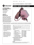
1
ValveBank 4 & 8 II
812 Page St
Berkeley, CA 94710
U.S.A.
(800) 998-MATE
-6283
User’s Manual
Version II 1.4
ValveBank4 & 8 - Part #s 01-01 & 01-08
For indoor use only from 5° to 40° C.
Do not get wet or subject to visible condensation.
Clean with a mild soap solution with a damp cloth only.
ValveBank£4 & 8 II
This equipment must be earth grounded. Use any of the screws on the
bottom or side of the case. See page 15.
!
Do not unplug valves while on!
Do not attempt to repeatedly cycle valves on and off in under 10
milliseconds.
If this equipment is used in a manner not specified by the manufacturer,
the protection provided by the equipment may be impaired.
Supply voltage:
ValveBank controller = 12 V AC up to 2.4 Amps @ 50-60 Hz
External power supplies:
USA & Japan = 110 V AC up to 0.26 Amps @ 60 Hz
European = 220 V AC up to 0.17 Amps @ 50 Hz
Internal battery type:
3V Lithium coin battery
type BR2325 coin or CR2032
User’s Manual
Version II 1.4
23mm x 165mAh
Please replace fuse with standard 2.5 Amp (M) medium-time / blow fuse.
European CE Technical Representative:
AutoMate Scientific
Elisenstr. 16, Leverkusen 51373, Germany
For research use only.
Josef Kewekordes II, Heath Lukatch
David Ilstrup, Gabriel Stern, Brian Greenstone, EPP
©1996, 2000 AutoMate Scientific, Inc.
All rights reserved.
7, -t
Do Not Unplug Valves while Energized!
The resulting voltage spike is much like a car
spark plug, and will destroy circuit board
components.
Do Not Clean the ValveBank Screen With
Paper Towels – It Will Scratch! Use a cloth
with a 50% alcohol solution.
This equipment must be earth
grounded. Use any of the screws on the
bottom or side of the case.
Table of Contents
Introduction ............................................................................................. 3
Hardware Overview .....................................................................................3
ValveBank Laboratory Applications ..........................................................4
User’s guide notation ...................................................................................4
Care of your ValveBank screen ...................................................................4
Mounting Options & Assembly ..................................................................5
ValveBank Accessories .................................................................................5
EasyCode™ Software for Macintosh and IBM-PC...................................6
Luer lock Valves & Syringe Reservoirs ......................................................6
Pressure Regulated Perfusion System........................................................7
Multi-barrel Perfusion Pencil™ ..................................................................7
System Set-up Diagrams ....................................................................... 8
Perfusion System ...........................................................................................8
Standard PTFE-Inert Perfusion System (without pressure)....................9
Chromatography .........................................................................................10
Gel/Blot Washing System ..........................................................................10
PTFE-Inert Micro-manifold Use................................................................12
Perfusion Pressure Kit ................................................................................13
Multi-barrel Perfusion Pencil ....................................................................14
Case & Valve Grounding ...........................................................................15
Back Panel ....................................................................................................15
Main Menu ............................................................................................ 16
Manual Mode ........................................................................................ 18
Manual Mode Special Features Menu......................................................19
Edit Program Mode .............................................................................. 21
Saving a Program ........................................................................................22
Next Time/Command Prediction.............................................................23
Commands ............................................................................................. 25
Loops.............................................................................................................26
Loop Structures ...........................................................................................27
TTL-Input Commands................................................................................27
Timing diagrams .........................................................................................29
The ValveBank is intended for research use only.
The ValveBank line is dedicated to the memory of Victor A. Rivas.
1
Introduction
Run Mode ............................................................................................... 30
Networking multiple ValveBanks ............................................................30
Running Programs ......................................................................................30
Single Repeat Running - Microinjecting ..................................................31
Manual Mode Special Features .................................................................31
Serial Mode ............................................................................................ 32
File Mode ................................................................................................ 33
Clear All Memory........................................................................................33
PLEASE SET ASIDE SOME TIME TO READ THIS MANUAL
BEFORE USING YOUR NEW VALVEBANK SYSTEM.
The ValveBank is a very unique and sophisticated programmable
tures without reading this manual. Thanks!
Computer Interfacing ........................................................................... 34
Valve Driving ...............................................................................................34
Feedback to a recorder................................................................................35
Slave Mode Computer Interfacing ...........................................................35
Techniques ............................................................................................. 36
Dead Volume ...............................................................................................36
Small-bore PTFE-Inert Tubing...................................................................36
.......................................................................................................37
Syringe Reservoirs ......................................................................................37
AutoPrime™ System ..................................................................................37
Faulty Valves................................................................................................38
Stuck pinch Valves ......................................................................................39
Valve Cables .................................................................................................39
Valve Returns & Replacing a Valve ..........................................................40
..............................................................41
EPROM Installation Instructions ..............................................................42
......................................................... 43
Networking multiple ValveBanks ............................................................43
Repeat Run ...................................................................................................43
Normally Open/Closed Valves ................................................................44
3-way Valves ................................................................................................44
TTL Input/Output Logic ...........................................................................45
TTL Port ........................................................................................................45
Serial Cable ..................................................................................................45
Troubleshooting...........................................................................................46
EasyCode™ Macintosh & PC Software ........................................... 47
Sample Programs .................................................................................. 48
FOR RESEARCH USE ONLY
The ValveBank is designed for solution-switching use in research
for injury or death resulting from medical or pharmacological use.
Hardware Overview
The ValveBank™
pump controllers with 10 millisecond accuracy. Programming and
manual control is accomplished through a 16-key membrane keytotaling 64K of battery backed-up (stored even when unplugged)
RAM memory.
The ValveBank is designed to drive 12 volt DC solenoid valves
*
plugged into RCA jacks on the back of the box. Four TTL outputs
are provided for interfacing the ValveBank with external devices
which receive 0 /+5 volt signals. These TTL channels can be proFour additional TTL inputs can monitor such instruments
puts can be programmed to trigger valve or TTL output activity. A
user-created computer program can also use these inputs to control
valves through the ValveBank. See the Computer Interfacing chapter.
NOTE: The ValveBank8 has only four TTL in and outputs.
Safety Instructions ................................................................................ 51
Warranty.................................................................................................. 53
2
chapter for more information and uses.
3
ValveBank Laboratory Applications
Perfusion
One or more ValveBanks can be programmed to precisely switch solutions perfusing over biological samples for physiological research.
The ValveBank’s circuitry is designed to open valves with low noise
Mounting Options & Assembly
We would like to explain the small items in the plastic bag included
is that the keypad and liquid crystal screen are now separated by
cable from the main unit in what we call the “calc.” Now your
ValveBank can be mounted away from your experiment area (even
perfusion use.
adhesive magnetic tape for several calc mounting options. These
three choices are left for you to decide how to best mount the calc
Washing
removable Velcro or magnetic tape.
mated and which are handled conventionally. Unattended washing
can save a busy lab countless hours of tedious monitoring.
The ValveBank main unit also has two options. Four additional
feet are included for simply leaving the ValveBank on the bench
top; or rack-mounting brackets and screws can also be purchased
separately.
Liquid Chromatography
A ValveBank can be easily programmed to automate solution
ValveBank Accessories
matography runs with excellent reproducibility. The ValveBank
is especially useful in preparative work when a protocol has been
established and programmed to repetitively isolate your valuable
molecule.
entire perfusion systems.
User’s guide notation
shown in bold type: <Enter> or <Cancel>
or as keys:
ENTER
CANCEL
Care of your ValveBank screen
Avoid scratching the screen cover by cleaning it with a 50% alcohol/
Oocyte Chamber
Part #OPC-1
4
Petri Dish Chamber
Part #PCP-1
Pinch Valves (set of 4)
Part #02-pp-04
5
EasyCode™ Software for Macintosh and IBM-PC
Pressure Regulated Perfusion System
EasyCode software for the Macintosh and IBM-
programs to the ValveBank through its serial port. See page 47.
The package can be added to
any new or existing perfusion
NaOH 0.1 M
Buffer 1
or even homemade. Connect
Sample 1
Krista#17-4
compressor (30 to 100 psi).
Precision regulator delivers
NaOH 1.6 M
Buffer 2
syringe reservoirs.
Final Wash
Timed Pump
Luer lock Valves & Syringe Reservoirs
Part #09-04
Part #09-08
Part #09-16
4-channel
8-channel
16-channel
For Single-cell or Whole-cell Superfusion
Perfusion Pencil® Multi-Barrel Manifold Tip
direct connection of syringes.
This method eliminates
wasted solution in tubing
between the reservoirs
and valves. Small 2-way
stopcocks are included when
this option is ordered.
motor translation. No clumsy
rotating valves.
For mounting on any
micromanipulator.
removable tips
available
6
7
System Set-up Diagrams
Pinch Valve, Pressurized and Luer-Lock Perfusion Systems
(1)
Standard PTFEInert Perfusion
System (without
(3 & 4)
perfusion systems please see the previous page. Luer lock systems should
also see the photo on page 6. Find additional photos and diagrams of the
pressure system on pages 7 and 13.
pressure)
Also see the "Installation Tips"
section on the next page.
(1)
(5)
Drippers are NOT included
with these systems because the
syringes are inserted directly into
valves.
- no room for
drippers and may interfere with
pressure in tubes. Use provided
male luer locks to connect tubing
above each valve.
(3)
Roller "thumb" clamps
can be used here
(6)
(2)
(2)
(4)
To chamber
& vacuum
trap (8)
(5) To perfusion chamber
and vacuum trap
(7) Green clamps
close to manifold
1) Assemble ringstand rod and base.
2) Attach valve unit.
3) Attach reservoir bracket(s).
4) Insert syringes with stopcocks.
long enough to move reservoirs.
7) Insert green clamps on pieces of
1/16" tubing between bottom valve
barbs and manifold.
1) Assemble ringstand base and rod.
2) Attach valve unit.
3) Insert syringes with stopcocks.
5) Insert short pieces of 3/16" i.d. tubing
your perfusion chamber.
6) Attach dripper tubing to upper valve
8
9) Plug numbered valve cables into
ValveBank ports.
Simply slide larger tubing over
small pinch valve tube above and
below the valves.
4) Connect tubing between bottom
valve tube and manifold.
your perfusion chamber.
6) Plug numbered valve cables into
ValveBank ports.
9
Installation Tips
Perfusion Cheat Sheet
may still help.
and lower the reservoirs.
Adjust flow rate by height of syringe reservoirs.
for running cleaning solutions and drying your lines quickly.
Watch flow rate in drip chambers
Adjust flow rate with thump clamp
period of time.
Valves
As long as these tubes are prefilled (primed)
with solution, then opening valves upstream
starts liquid flowing inside the manifold here.
Cover and ground
suction tube with
aluminum foil
to minimize noise
Bubbles and Degassing
Bubbles are often caused by outgassing. This is particularly true when
media is stored cold overnight and allowed to warm to room temperature
will form in the tubing and valves as gas leaves the media. The best
solution is to pre-warm your solutions by at least 2-3 degrees above
room temperature even if you are adding gas (CO2
it is a good idea to warm solutions 2-3 degrees above your inline heater
Inflow manifold
Ground
electrode
slots
Suction tube
Flow rate
adjustment
screw
the solutions in the reservoirs at this higher temperature all day using
reservoir heaters.
Good liquid level
Degassing can also be facilitated by applying a slight vacuum to the
Suction tube well:
your media.
Networking multple ValveBanks
BAD!
Connect the Valvebank’s together with the provided cable with plug #1 to
the master’s TTL In/Out Port and plug #2 in the secondary unit.
10
GOOD
Caution:
May suck chamber dry,
but may stop oscillations.
11
PTFE-Inert Micro-manifold Use
Perfusion Pressure Kit
(Sold separately)
Press regulator knob down to lock.
Pull up to unlock.
hose barbs. Micro-manifolds are shipped with a short piece of 1/16”
the valves to manifold inports with a piece of 1/16” i.d. tubing over
both the valve barbs and short pieces of manifold tubing:
Valve with 1/16” o.d. barb
Max. input
pressure 100 psi!!
Individual air lines can be
v
1/16” i.d. tubing over barb
and over manifold short tubing
v
Manifold with short pieces of 1/16” o.d. tubing in each port
i.d.
o.d. tubing
inserted inside the valve tubing and manifold ports (you may need
to supply extra small tubing for this option):
Be very careful with these
plastic hose connections.
less dead volume
Valve with 1/16” o.d. barb
v
Short piece of 1/16” i.d. tubing over valve barb
v
Small diameter 1/16” o.d. tubing inserted inside valve tube
and inserted inside manifold ports
v
Manifold without connector tubing. 1/16” i.d. holes.
Press bottom button to empty.
Syringes may also be placed in a water
bath for temperature control.
Cutting the tubing at an angle will make insertion easier. Cutting
at the point of convergence.
2-way stopcocks and luer-lock to 1/16
included for each channel to connect syringes to hose.
Hoses should continue from syringes to valves.
Remember to keep all tubing as short as possible.
12
13
Perfusion Pencil Multi-barrel Manifold
Back Panel
(Sold separately)
12 V AC Power (up to 2.4 Amps @ 50-60 Hz)
Keypad (calc)
One of the eight lines may be connected to
vacuum through a valve programmed to suck
the dead-volume clear between solutions.
Tighten removable tip for
minimum dead volume.
Chemical Information
The tubing inside the manifold body is polyimide (nylon). The removable tips
microliters of solution before using the device. The Perfusion Pencil and removable
Serial (RS-232) Ports:
In (computer) and Out
(next device in chain)
See page 32.
Digital (TTL) port
See page 45.
12 V DC valves
Case & Valve Grounding
This equipment must be earth grounded. Use any screws on
the bottom or side of the ValveBank case for grounding. Order
Maintenance
You can expect several years of useful lifetime for your tip if you wash it daily.
Cutting
The removable tips are shipped with 0.5" (1 cm) length polyimide needles.
package” for an extra grounding wire attached to each individual
valve extending back to the controller. Each of this item grounds
four (4) valves. Please order two for eight channel perfusion
systems. This item must be ordered at the same time as the valves.
Connect the ground wire from the valves to a screw on the bottom
or side of the controller case.
coating of the needle with a ceramic cleaving stone or a diamond cutter and pull
Part No.
#04-04-xxx
#04-08-xxx
#04-16-xxx
14
4-into-1 Pencil with tip
8-into-1 Pencil with tip
16-into-1 Pencil with tip
Replacement Tips:
15
Main Menu
ValveBank™
Select Function:
Run Mode
=== AutoMate ===
T Manual Mode V
1C 2C 3C 4C
5C 6C 7C 8C
This notation is used throughout the manual to represent the
ValveBank’s liquid crystal display. The ValveBank8 uses a 4-line by
The ValveBank displays two introduction screens every time
it is turned on. These can be advanced by pressing any key.
keys
Scroll through 6 menu choices.
|
Run Mode
|
Run an existing program
|
Manual Mode
|
Open/close valves manually
|
Edit Program
|
Write a new program or
edit an existing one
|
File Mode
|
Copy and erase programs
|
Serial Mode
|
Transfer programs to/from
your personal computer
Adjust preferences
Each Mode is discussed in its own chapter later in the manual.
ENTER
16
<Enter> key
Selects current menu choice.
CANCEL
ENTER
/
1-8
9/0
Manual Valve Commands
Pause / End Program + ALL Valves Close
Resume + Buzzer Off + Special Features
Toggle 1-8 Control Valves or TTL outputs
Open/Close Valve or TTL outputs
ALL Open / Close
1
2
3
ENTER
4
5
6
CANCEL
7
8
9
0
Menus:
ARROWS change selection
ENTER makes selection
CANCEL returns to last screen
AutoMate Scientific, Inc.
The ValveBank8 'Calc'
17
Manual Mode
Manual Mode Special Features Menu
Manual mode allows user control of valves and TTL outputs for
MANUAL MODE V
1CL 2CL 3CL 4CL
<— Status Bar (see below for explanation)
A low click from valves indicates opening or closing. A hum from a
valve indicates that it is holding open at the appropriate voltage.
V
T’TL Mode
Look for a V or T in upper right corner. Selects
ENTER
Makes selection.
Jumps to next screen.
Leave Manual Mode
Closes all valves and sets all TTL outputs to Low
Answer Yes to run a user program
from Manual Mode. The current
valve and TTL state is preserved
(may be changed later by your
program). Control is returned to Manual Mode after the program is
ing open). Useful for running a protocol after establishing a stable
baseline or pre-programmed wash-outs and line priming.
ENTER
Status Bar
V
’ne-at-a-time Mode
T’TL
(see above)
|T Manual Mode OV|
| 1CL 2CL 3CL 4CL|
#VT
18
Use Timed Open?
Yes
>No
Timed valves:
1Y 2N 3N 4Y
open after pressing #0 for All Closed.
>> T=00:00:20.00
Enter Duration
When Timed Manual Mode is
will remain open only for pre-set
amount of time then close again (opening the Master channel
Arrows> above)
Inverted number is
a Master channel
(see next page)
{
T’ means
Timed Manual
Mode is in use
(see next page)
Manual Mode Special Features Menu
(see next page)
Choose a master:
1
2< 3
4
Using a Master channel insures at least one valve is always open.
Master channel does
valve will close all others (for perfusion use).
Returns to Manual Mode.
Run a program?
Yes
>No
Edit master ch?
Yes
>No
CANCEL
CANCEL
T = TTL state ..........(H)igh / (L)ow
V = Valve state .......( )pen / (C)losed
# = Channel # ........1 through 4 or 8
Timed channels will
9 All Open.
insures that no more than one valve is open at
a time. Opening any valve closes all others.
Pressing #9 for All Open ignores One-at-a-Time Mode.
19
Edit Program Mode
Examples
Manual Mode V
1OH 2CL 3OL 4CH
Progressive example
Manual Mode V
1CL 2CL 3CL 4CL
Manual Mode V
1OL 2OL 3CL 4CL
Ch. 1 Valve = pen
TTL = High
Ch. 2 .................. Closed ............... Low
Ch. 3 .................. pen .................. Low
Ch. 4 .................. Closed ............... High
Keys pressed
1
2
Result (underlined
on next display)
Control diagram of a user program
Open valves 1 and 2
Switch to TTL mode
Manual Mode T
1OL 2CL 3CL 4CL
9
Open All = All TTL
output's High
Manual Mode T
1OH 2CH 3CH 4CH
0
Close All = All TTL
output's Low again
Manual Mode T
1OL 2CL 3CL 4CL
7
Manual Mode V
1OL 2OL 3OH 4OH
20
8
TTL 3 and 4 'On'
Switch back to
Valve mode
9
CANCEL
Ch 3 & 4
...8
Channel 2
Close valve 2
Manual Mode V
1OL 2CL 3CL 4CL
Manual Mode V
1OL 2CL 3CH 4CH
ValveBank4 holds 36 programs (ValveBank8 holds 18) in battery
Channel 1
2
Manual Mode T
1OL 2CL 3CH 4CH
The Edit Mode is used to create and modify user programs. Each
program is separated into four channels. Each channel controls its
TTL
Input 1
Valve 1
Select Program
Program=01
Valve 2
TTL
Output 2
<Enter> to Select Program
<Cancel> return to Main Menu
Enter 2 digit program number (1-36)
Underline represents the blinking
cursor where you are typing
Select Program
BLANK PROGRAM!
The ValveBank will indicate when
you are creating a new program in
an unused slot. Since you intended to
and continue. . .
Open All (valves)
Exit to main menu
All valves & TTL close
TTL
Input 2
TTL
Output 1
Select Channel
Channel=1
<Enter> to Select Channel
<Cancel> return to previous screen
or Save Program after editing
Enter 1 digit channel number (1-4/8)
21
Editing a Program
Line number (see
below)
01 T=00:00:00.00
Ch1 END OF LIST
Time line:
Set time value using arrows and digits
Move the cursor up/down one line at a time
Overwrite OK?
> YES
NO
<Enter> to make selection
<Cancel> returns to previous screen
change selection
message and returns the user to the main menu.
Next Time/Command Prediction
When cursor is on the line number:
Browse up/down two lines (one event) at a time
Note: You cannot scroll past the END OF LIST.
Time line: Move between time digits & line number
Cmd. line: Change commands (see next chapter)
ENTER
CANCEL
CANCEL
<Enter>
or <Cancel> to return to the Select Channel
screen and repeat the programming process for
all four channels in a program.
<Cancel> from Select Channel returns to the
Save Program screen if you have made any changes.
The ValveBank only predicts after you've changed the previous line.
Total Loop Time Calculation
Loop structures are explained in the next chapter on Commands.
length of the loop multiplied by the number of iterations you have
need to revise subsequent command times accordingly.
Example:
Saving a Program - Save often entering long programs!
None of the changes you make are permanent until you save them.
you want to save the changes:
Save Program
> YES
NO
22
<Enter> to make selection
<Cancel> return to previous screen
change selection
04 T=00:00:10.00
Ch1 LOOP STRT 12
09 T=00:00:20.00
Ch1
LOOP END
10 T=00:02:10.00
Ch1
VALVE ON
Bank determines when the loop will
be completed and enters this time on
the next command line.
iteration.
23
Commands
Programming Example
three for six hours (follow the underline cursor in the examples!)
Progressive display
Select Channel
Channel=1
Keys Pressed
Result (see next screen)
ENTER
Start new program.
Begin with channel 1
01 T=00:00:00.00
Ch1 END OF LIST
Move right and down
01 T=00:00:00.00
Ch1 END OF LIST
Several
times
01 T=00:00:00.00
Ch1
VALVE ON
Several
times
01 VALVE ON
02 BEEP
03 VALVE OFF
00:00:10.00
00:00:10.00
00:00:20.00
01 VALVE ON
02 VALVE OFF
00:00:20.00
00:00:01.00
Legal structure
Illegal structure
Error checking is built into the Save Program screen
to check for these illegal structures.
CANCEL
2
ENTER
Several
times
01 T=00:05:00.00
Ch2
VALVE ON
02 T=06:05:00.00
Ch2
VALVE OFF
CANCEL
Save Program
> YES
NO
ENTER
Move to minutes digit
Enter time (5 minutes)
then move down
5
01 T=00:00:00.00
Ch2 END OF LIST
24
Time values for each event in a channel must be
greater than or equal to the previous event's time.
Times represent when
NOT durations.
02 T=00:05:00.00
Ch1
VALVE OFF
Select Channel
Channel=2
Scroll through
commands to Valve On
Next line
02 T=00:00:00.00
Ch1 END OF LIST
02 T=00:00:00.00
Ch1 END OF LIST
Warning:
CANCEL
<Cancel> to
program other channel.
Select next channel
VALVE ON
VALVE OFF
TTL ON
TTL OFF
BUZZER ON
BUZZER OFF
your experiment for a few minutes.)
Change times and
commands as above
time and command
BEEP
Type <Cancel> 2x to jump
to “Save program” screen
INSERT LINE
Type <Enter>
saving program
<Cancel> always aborts
DELETE LINE
/4 second
1
Moves current line down and inserts a new line in its
place for adding new commands in existing programs.
Leaves a "BLANK" placeholder.
Deletes the current program line and moves next line
up. This is permanent!
25
END OF LIST
Warning:
Automatically inserted by the ValveBank after
the last user command; or can be entered by the
user to erase an existing channel. Represents the
last line of a channel's programming. A running
Loop Structures
LIST in all four channels.
available program lines. Loops on the ValveBank can also be nested
(used inside one another) up to four deep.
User can never scroll down past a END OF LIST
inserted END OF LIST will be inaccessible & lost.
If END OF LIST
is entered
accidentally:
(1) Press <Cancel>
(2) Do not Save Program
(3) Return to Select Program screen
(4) Re-load the last saved version of your program
- This will erase any changes made since
the last time the program was saved but will
recover any programming the END OF LIST
erased. Decide whether lines lost are worth
Loops provide a powerful means of grouping repeated operations.
heavily used VALVE ON/OFF and TTL ON/OFF combinations
Outer Loop Start
Inner Loop 1 Start
Inner Loop 2 Start
Inner Loop 2 End
Inner Loop 1 End
Outer Loop End
Nested
Loops
Each channel is limited to 16 loops.
Multi-channel Loops
You may want to repeat command sequences from several channels.
at exactly the same times in all channels to be included.
BLANK
A place-holder command which performs no
function when executed by a program.
Loops
LOOP STRT X01
LOOP END
Set start time for an upcoming LOOP END
command and number of iterations.
Set loop ending time.
06 T=00:12:04.00
Ch1 LOOP STRT 01
06 T=00:12:04.00
Ch1 LOOP STRT 01
06 T=00:12:04.00
Ch1 LOOP STRT 13
26
<Dn Arrow> to access
number of iterations
1
3
Channel 1
Loop Start 00:00:00.00
VaLVe on 00:00:00.00
VaLVe off 00:00:05.00
Loop end
00:00:12.00
VaLVe on
VaLVe off
Loop end
00:00:05.00
00:00:10.00
00:00:12.00
TTL-Input Commands
to set
See
ENTER or
Channel 2
Loop Start 00:00:00.00
to invert High/Low logic.
<Enter> or <Down
Arrow>
27
TRIGGER ON
Must be followed by a TRIG LENGTH command
(which is automatically inserted and deleted by the
ValveBank). The TRIGGER ON command instructs
the ValveBank to begin watching the TTL input
associated with its channel. When that TTL input
Timing diagrams
(Sample TTL input is bottom graph)
TTL RESPOND 00:00:05.00
TTL IGNORE 00:00:16.00
On
command. If the TTL input is already High when
is opened immediately and timed according to
the TRIG LENGTH as usual. TRIGGER ON only
triggers once. Use loops to repeat trigger.
TRIGGER ON 00:00:05.00
TRIG LENGTH 00:00:05.00
Either a VALVE ON or VALVE OFF command will
discontinue a pending TRIGGER ON command
and override any TRIG LENGTH time remaining.
TRIG LENGTH Cannot be entered by itself. Automatically inserted
(or removed) by the ValveBank following a
Valve output
On
VALVE ON
00:00:00.00
TRIGGER OFF 00:00.05.00
On
to hold a valve open when TRIGGERed. Cannot be
ON partner with an INSERT LINE. You must
change or delete its TRIGGER ON to remove it.
TRIGGER ON 00:00:04.00
TRIGGER ON 00:00:16.00
TRIG LENGTH 00:00:02.00
TRIG LENGTH 00:00:02.00
VALVE OFF
00:00:05.00 (disables
pending TRIGGER ON or OFF)
On
TRIGGER OFF command instructs the ValveBank
closes that channel’s valve (assuming it was open).
TRIGGER OFF is discontinued by a VALVE ON or
OFF just like TRIGGER ON.
High
Low
Computer
Interfacing chapter for more TTL input information.
28
t=0
5 sec.
10 sec.
15 sec.
29
Run Mode
Select Program
Program=01
Press A Key To
Start Program
Additional manual commands while a program is executing:
<Enter> to Select Program
<Cancel> return to Main Menu
Enter 2 digit program number (1-36)
<Enter> to begin execution
<Cancel> to abort
1st press:
CANCEL
Pauses any running program
All valves and TTL’s remain open or
closed as they were when paused
Returns to Main Menu
ENTER
Resumes paused program
Networking multiple ValveBanks
Slave units will display:
Waiting For
Master Start
<Cancel> to abort
(see
chapter p. 43)
A pulse from the Master ValveBank will now start programs running
on all properly wired Slave units waiting on this screen.
output status is displayed. (Fractions of seconds are not displayed)
<— Time line
<— Status bar
(See Manual Mode
chapter for status codes)
functional except <Enter> to access the Manual Mode Special
Features Menu. See the Manual Mode chapter (p. 18) for information
on commands available and a description of the status bar. An
additional code appears on the status bar while a program is
running:
‘X’
Program is completed when all four channels are done.
30
All valves Closed (unless run
from Manual Mode)
and completion time shown.
Press <Cancel> to return to Main Menu.
CANCEL
Single Repeat Running - Microinjecting
Running Programs
01 T=00:13:08 V
1OH 2CL XOL 4CL
01 T=07:36:11.84
Program Finished
1
1
Press key <1> twice after a program
microinjecting repeatedly.
See Repeat Run in
for rapid repeating.
Manual Mode Special Features
Modes) are
still work for manually toggling valves open and closed. (See pg.
Mode since <Enter> will not access the Special Features Menu while
running a program.
31
Serial Mode
File Mode
Serial mode is used to transfer programs back and forth between the
ValveBank and a computer running the AutoMate graphic programEasyCode. Programs can be entered and edited on
> COPY Program
ERASE Program
ENTER
Make selection
CANCEL
Return to Main Menu
COPY Program will request a SOURCE program (with a warning
if the source is blank) and the DESTINATION program (with
Select Transfer:
> SEND
RECEIVE
move cursor
<Enter> select menu option
<Cancel> abort to Main Menu
Follow the instruction found in the EasyCode manual for preparing
your computer to send or receive information with the ValveBank.
Press <Enter> on the ValveBank when EasyCode tells you it is ready.
used).
Clear All Memory
This command should be used with extreme care! Entering 99 on
ValveBank —> Computer (send)
Select Transfer:
>SEND
RECEIVE
Select SOURCE
Program=01
ENTER
Load a ValveBank user
program then transmit
it to a host computer.
ENTER
Computer —> ValveBank (receive)
Select Transfer:
SEND
>RECEIVE
ENTER
Destination:
Program=01
ENTER
Start a receiver
Receive a program then
save it in a ValveBank
program slot.
you may wish to clear all memory and re-send programs stored on
your Macintosh or PC in the EasyCode program to the ValveBank by
Serial Mode (assuming you have EasyCode).
Clear All also resets all
and Manual Mode Special
Functions settings to their factory defaults.
<Cancel> will abort during transfer.
CANCEL
See page 45 for a serial cable diagram.
32
33
Computer Interfacing
Feedback to a recorder
It is also possible to program the ValveBank to provide
Using the AutoMate EasyCode
ValveBank program sequences on a PC and send them to the
ValveBank’s memory. Programs are then run on the ValveBank.
reference exactly when valves were opened or closed. Just include
TTL ON commands immediately after VALVE ON’s and monitor
the four TTL outputs on the ValveBank.
developing custom timing and data collection programs on their
personal computers to automate their research. The ValveBank can
still be invaluable for these users both for Manual Mode calibrating
and as an advanced valve driver under computer control.
Valve Driving
VALVE ON
TTL ON
TTL OFF
00:00:12.55
00:00:12.55
00:00:13.55 (for a one second pulse)
Use other pulses for valve closures or important timing milestones.
ValveBank TTL inputs with their own custom programs.
Both the Valve Driving and Feedback strategies discussed so far
can be combined with normal ValveBank programming in separate
channels.
Why not connect valves directly to your computer? Several reasons:
Slave Mode Computer Interfacing
With four TTL pins from an interfacing board on a personal
See the next chapter about wiring multiple ValveBank’s together
enough to drive most valves (6 to 12V DC and up).
2) Computer interface signals are often too noisy for electroConnect your computer TTL output pin to input pin number one on
the valves from heating. The ValveBank automatically provides
dual-voltage hold-in even when being controlled by an external
computer.
The easiest way to drive valves through the ValveBank is to write
a short program with a TTL RESPOND command in each channel
the program length). Then set Repeat Run ON in the
menu. Connect your four interface signals to the four TTL inputs
on the ValveBank (see the
chapter) and run this
program. The ValveBank will open and close valves exactly
mirroring the computer signals (with 10 millisecond accuracy).
34
Signal into
TTL Input pin #1
+5
Slave ValveBank(s) will
start their programs here
10 ms
minimum
0V
t
Note: TTL Input #1 can still be used on slave ValveBanks after their
start signal.
35
Techniques
Backflow
-
Dead Volume
as rapidly as possible. Dead volume for this purpose refers to the
volume in the single piece of tubing between the manifold and
amount of time must pass for a new liquid to clear the previous one
with AutoMate Perfusion System drippers which can be easily attached to short pieces of tubing to act as plugs for unused holes.
Ordinary solution pressure in other lines will force liquid back
manifold - assuming each channel’s tubing has been primed from its
closed while changing connections.
some distance away. The micro-manifolds available from AutoMate
AutoMate Perfusion Systems include a blue disposable
increase dead volume if used improperly.
before the manifold to eliminate dead
individual solutions (instead of all solutions when located after the
Syringe Reservoirs
to its 100ml polypropylene reservoir cups. Connected directly
solution in tubing between the reservoirs and valves. Small 2-way
stopcocks are included when this option is ordered. These are
be disconnected before completely empty. Simply loosen the luer
lock
together. These stopcocks are also useful if there is a chance of a
valve opening after its reservoir is empty (see above paragraph).
AutoPrime™ System
same switching time as for larger tubing.
The AutoPrime Perfusion System is
designed to deliver oxygenated (or
other gas-saturated) solutions without
Small-bore PTFE-Inert Tubing
1
small bore use. Also see the micro-manifold instructions on page 12.
Cutting PTFE-Inert tubing at an angle makes it easier to insert.
36
2
3
remained stationary in the tubing long
enough to lose its oxygenation. Unless one
4
waste
™4
ValveBank
tific, Inc
ate Scien
AutoM
gas will escape through the tubing leaving
the stale solution with a ruined pH and gas
concentration. The 8-channel AutoPrime
37
the upper tubing with fresh solution from the reservoir down to its
elevated temperatures because of the increased probability of
electrolytic corrosion.
3) Do not operate AutoMate valves with homemade controllers
4) Do not exceed the rated operating pressure (> 100psi).
opened. The previous solution in a delivery sequence can continue
Faulty Valves
The bane of all liquid delivery apparatus! Despite AutoMate’s
valves fail. How often have space shuttle launches been delayed
due to valve problems? We can only pass along our valve supplier’s one year warranty with their disclaimer “Improper use or
Before returning any valves to us please check:
1) That it was purchased in the last 12 months (AutoMate
and valve manufacturers record each by serial number.)
2) That the valve is faulty and not the controller channel
bad valve in that port to see that it still does not function.
valve for subsequent return to the factory. Repair or replacement
the valves to determine the cause of trouble. We may be able to loan
1) Clean your valves after each use. Accumulated debris
or precipitate will rapidly cause leaking valves and seals. Use an
abuse on the user’s part and refuses to honor the warranty.
solutions. Put your AutoMate controller’s programmability to good
Stuck pinch Valves
reservoir with cleaning solution (distilled water or appropriate
each valve in sequence. Saline solutions allowed to dry in stainless
steel valves will cause them to rust. This is considered improper
use.
valve that is suspected to have failed for this reason by connecting
of the valve while it is
Occasionally pinch valves will stick closed. Usually this is a sign
plunger open where it normally pinches the tube closed. The
pinch valves will not
Valve Cables
connection. Use any ohmmeter to measure the resistance across
2) Use appropriate valves for a given application. Use
of caustic or corrosive liquids with our stainless steel valves
soon as they open them. Please request our PTFE-Inert isolation
valves if you plan on using such solutions. We even recommend
isolation valves for highly conductive saline solutions and/or
38
is broken in the cable assembly. This occurs most often at the joint
39
from the valve itself. This can often be reached without completely
disassembling the valve enclosure. Simply 1) remove the screw
inside the black valve box holding
4) Whether the valve was driven by any device other than an
AutoMate controller (and its operating and holding voltages).
Valve enclosure (shown without front plate)
remove the black tape at the top of
the sheath and peel it back a couple
and 3) carefully slice its heat-shrink
tubing longitudinally to remove
it. The wires may have come apart
piece of electrical tape isolating the
1
2
3
Heat
shrink
on each
cable
chemical(s) and the duty cycle (pulse) rate if used.
6) A Statement of Chemical Exposure as follows:
a) These valves have not been exposed to chemicals other than H2O
except as described above. b) All applicable Safety and Handling data
sheets for the above described chemicals are enclosed. c) We accept full
responsibility for any injury to AutoMate employees or employees of
the valves original manufacturer caused by handling of the residues
of chemicals contained in or on the valves to be returned.
AutoMate will gladly fax you a form with easy blanks to enter
the above information. We will process your return and notify you
of further information as quickly as possible.
the above instructions in reverse order.
Leaks & Replacing valve fittings
The second bane of liquid delivery apparatus! These hints may help:
Valve Returns & Replacing a Valve
2) See all of the guidelines in the previous "Faulty Valves" section
- especially #1.
and return the individual valve from its case. This only involves
4) Check and replace obvious loose or worn tubing.
valve on to the front plate.
Please package the valve(s) carefully and ship freight prepaid to
AutoMate’s address on the back cover of this manual.
as long as you include a note with the following:
easily cause clogs or leaks of their own.
glues will adhere to PTFE-Inert.
an address to return the repair to.
2) Your original invoice number and date if available.
3) A sentence stating the nature of the problem and any steps
40
41
Configuration / Technical Notes
EPROM Installation Instructions
1) Open the ValveBank case as described in 'Troubleshooting'
on page 46. Remove the last EPROM slowly
side. Insert the new chip with the same
ValveBank II 1.3 ___
pins.
uration and AutoMate normally-closed valves. The user may never
need to make changes to these options.
Networking multiple ValveBanks
pennies stamp cost for U.S. customers to drop them in an envelope back
to AutoMate. International (or busy U.S.) customers will be excused
if they cannot return old eproms. :-)
networked together. The MASTER box sends a start pulse (see pg.
written across several ValveBanks which each control their own
operate as though running a single program written for many
valves. Multiple ValveBanks should be connected through their
TTL In/Out Ports by a cable supplied by AutoMate. See page 11 for
a diagram of a double-ValveBank arrangement.
Select Box Type:
>MASTER
SLAVE
<Enter> to make selection & continue
<Cancel> return to Main Menu
toggle modes
Repeat Run
Repeat Run allows a user to run a program continuously. When
four days is to write a sequence (up to 99 hours long) which will be
Turn Repeat Run:
ON
>OFF
42
<Enter> to make selection & continue
<Cancel> return to Main Menu
toggle modes
43
Normally Open/Closed Valves
TTL Input/Output Logic
Normally-Open valves. AutoMate sells only Normally-Closed
(CL
powered) which is the default for this setting. Inverting a channel
to Normally-Open ( ) represents that valve receiving power on a
VALVE OFF command and no power when ON.
VALVES Normally:
1-4: CL CL CL CL
<Enter> continue to next screen
<Cancel> return to Main Menu
<1..4 (or 8) > toggle each channel
NOTE: Normally-open valves
The ValveBank must supply power continuously to keep normallyopen (N/O) valves closed even while no program is running. If the
These two settings allow the user to invert the TTL logic on
incoming and outgoing TTL port signals for use with TTL ON
and OFF commands and Manual Mode. TTL is an electronics
abbreviation for Transistor-Transistor-Logic representing simple
signals being transmitted as either 0 volts (ground) or +5 volts.
standard ON/OFF convention to Low=ON and High=OFF to suit
the particular electronic needs of a custom lab arrangement.
TTL Outputs:
1N 2N 3N 4N
<Enter> to next screen
<Cancel> return to Main Menu
<1..4> (or 8) toggle each channel
TTL Port
will turn 12V on for all N/O valves as soon as it is powered-on
and whenever a user program ends. This is intentional to insure
Pins 11-13 =
TTL outputs 1-3
is on. They should not heat-up appreciably and this should not be
solutions are otherwise blocked (ie. manual thumbwheel valve) you
may wish to stop the ValveBank from supplying power to the valves
while the ValveBank is turned on. Choose
from the
Main Menu and temporarily switch all valves to normally-closed.
The ValveBank will stop supplying power to the valves thinking
they are normally-closed. Set them back to normally-open before
3-way Valves
after determining which of two inlets or outlets are opened with
VALVE ON and VALVE OFF commands. These can be reversed
above.
44
Pins 3-10 =
TTL inputs 1-8
Pin 2 = +5 V
Pin 1 = ground
13
1
25
14
Pins 19-25 = reserved
(DO NOT CONNECT!)
Pins 14-18 =
TTL outputs 4-8
Serial Cable
ValveBanks communicate with EasyCode and other serial sources
using a 'null' modem cable or standard serial cable with 'null
modem' adapter with the following simple wiring:
1
1 (ground)
2
3
3
2
45
EasyCode™ Macintosh & PC Software
Troubleshooting
Should the ValveBank screen and power LED fail to light while
its bottom and check the fuse on the internal circuit board. Only
replace the fuse with a standard (not slow-blow) 2.5 Amp fuse. One
extra fuse is included on the circuit board in clips labeled “Spare.”
ValveBank which can be disconnected from the computer. See Serial Mode
on p. 32 for program transfer information.
Also see the Techniques chapter for more troubleshooting
information on problem valves and leaks.
The ValveBank is designed to drive 12V DC 2-way solenoid valves.
Its driver circuitry is overload and short circuit protected.
ValveBank4’s or 2 ValveBank8’s)
experiment
accurate to 0.01 seconds from the keyboard
- even between several experiments
multi-channel looping and interface
triggering
from the ValveBank to
print-out or modify
on screen or printed
Serial cable and
manual included.
46
6 or greater or PC running Windows 3.1.
47
Sample Programs
Chromatography (Ion exchange)
Perfusion
(Channel 1)
01 T=00:00:00.00
CH1
VALVE ON
02 T=00:05:00.00
CH1
VALVE OFF
Glutamate (Drug 1) for 1 minute
(Channel 2)
01 T=00:05:00.00
CH2
VALVE ON
02 T=00:06:00.00
CH2
VALVE OFF
(Channel 4)
01 T=00:06:00.00
CH4
VALVE ON
02 T=00:09:00.00
CH4
VALVE OFF
NMDA (Drug 2) for 5 seconds
(Channel 3)
01 T=00:09:00.00
CH3
VALVE ON
(Salt 1) for 1 hour
(Channel 1)
(Salt 2) for 3 hours
(Channel 2)
(Salt 3) for 1 hour
(Channel 3)
(Salt 4) for 2 hours
(Channel 4)
01 T=00:00:00.00
CH1
VALVE ON
02 T=01:00:00.00
CH1
VALVE OFF
01 T=01:00:00.00
CH2
VALVE ON
02 T=04:00:00.00
CH2
VALVE OFF
01 T=04:00:00.00
CH3
VALVE ON
02 T=05:00:00.00
CH3
VALVE OFF
01 T=05:00:00.00
CH4
VALVE ON
02 T=07:00:00.00
CH4
VALVE OFF
02 T=00:09:05.00
CH3
VALVE OFF
Turn recording device on
(Channel 1)
(Type <Enter>
without disturbing program)
END OF LIST at 1 hour
03 T=00:09:05.00
CH3
TTL ON
03 T=00:09:05.00
CH1
VALVE ON
04 T=00:09:05.00
CH1
BUZZER ON
05 T=01:00:00.00
CH1 END OF LIST
program reaches this point and ends.
48
49
Safety Instructions
Gel/Blot Washing
Please read all of these instructions carefully.
and 20 seconds to drain.
Fill tray with Blocking solution
(Channel 1)
01 T=00:00:00.00
CH1
VALVE ON
1. Follow all the instructions and warnings marked on this product or included in
this manual.
Wait for 12 minutes (washing)
02 T=00:00:30.00
CH1
VALVE OFF
causing serious damage to the product.
Drain
(Channel 4)
01 T=00:12:00.00
CH4
VALVE ON
3. Slots and openings in the cabinet and the back are provided for ventilation. To
02 T=00:12:20.00
CH4
VALVE OFF
or other similar surfaces. This product should never be placed near or over a radiator
or heat register. This product should not be placed in a built-in installation unless
proper ventilation is provided.
Prepare to repeat washes
(Channel 3)
01 T=00:12:20.00
CH3 LOOP STRT 03
Prepare to repeat drains
(Channel 4)
03 T=00:12:20.00
CH4 LOOP STRT 03
Fill tray with wash solution
02 T=00:12:20.00
CH3
VALVE ON
Wash for 15 minutes
03 T=00:12:50.00
CH3
VALVE OFF
Drain
04 T=00:27:00.00
CH4
VALVE ON
05 T=00:27:20.00
CH4
VALVE OFF
Repeat 3 times in both channels
04 T=00:27:20.00
CH3
LOOP END
06 T=00:27:20.00
CH4
LOOP END
50
or electric shock. Never spill liquids of any kind in the product.
5. This product should only be connected to the AC power source indicated on your
product system’s information label. If you are not sure of the type of AC power
a power outlet that matches the power requirements of this product.
6. Do not allow anything to rest on the power cord. Do not locate this product where
people will walk on the cord.
amperage rating of all equipment plugged into it does not exceed the amperage rating
main AC power outlet does not exceed 15 Amps.
8. Unplug your product from the main electrical power before cleaning. Do not use
liquid cleaner or aerosol cleaners. Use a damp cloth for cleaning.
9. Do not use this product near water.
51
Warranty
10. Unplug this product from the main power outlet and call for service under any
of the following conditions:
A.
B.
C.
D.
If the power cord or plug is damaged or frayed.
If liquid has been spilled into the product.
If the product has been exposed to rain or water.
If the product has been dropped or the cabinet has been damaged.
workmanship and/or material for
from the date of sale.
pre-paid to the factory (with a written explanation of the problem) for
service.
charge and return it to you.
precautions:
A. The power supply cord must be unplugged before the main system unit cover is
removed. (Separe le cordon d’alimantation et puis enleve le couvercle.)
power supply is plugged back in. (Apres le couvercle en place et remettre le cordon
d’alimentation.)
Battery Warning Statement
There is a danger of explosion if the battery is replaced incorrectly. Replace only
with the same or equipment type recommended by the manufacturer. Discard used
batteries according to the manufacturer’s instructions. See inside of front cover for
Il y a danger d’explosion s’il y a remplacement incorrect de la batterie. Remplacer
uniquement avec une batterie de meme type ou d’un type recommande par le
constructeur. Mettre au rebutled batteries usagees conformement aux instructions
expense of the customer.
Inc. will
with
accept the return of any products which have been used
or harmful environment.
indirect or consequential damages for the breach of any express or
or if this warranty is found to fail its essential purpose. AutoMate
denselben oder einen vom Hersteller empfohlenen ahnlichen Typ. Entaorgung
gebraushter Batterien nach Angaben des Herstellers. See inside of front cover for
country. All terms and conditions hereof shall be governed by the
laws of the State of California.
52
53