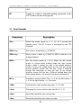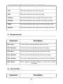
1
THE OBSERVATORIES OF THE CARNEGIE INSTITUTION OF WASHINGTON 813 Santa Barbara Street Pasadena, California 91101 Phone: (626) 577-1122 • Fax: (626) 795-8136 GUIDER CAMERA CONTROL SYSTEM SOFTWARE User Manual Document Code 01 - 00 - N8 Type User Manual Author Silvia Baeza and Jose M. Soto Date February 15, 2008 Revision Jose M. Soto Revisions Table Date Description February 15, 2008 Document update May 22, 2003 Document creation Original draft by Steve Shectman ii Table of Contents 1 GUIDER CAMERA CONTROL SYSTEM INTERFACE...................................................................................1 1.1 Starting the Camera..............................................................................................................................................1 1.2 Running the Camera.............................................................................................................................................1 1.3 Scaling the Display .............................................................................................................................................2 1.4 Guiding.................................................................................................................................................................3 1.5 Recording Data ....................................................................................................................................................4 2 COMMANDS SUMMARY.......................................................................................................................................5 2.1 Camera Commands..............................................................................................................................................5 2.2 Guider Commands...............................................................................................................................................6 2.3 Other Camera Commands....................................................................................................................................7 2.4 Cursor Commands................................................................................................................................................8 2.5 Message Commands.............................................................................................................................................9 2.6 Other Commands.................................................................................................................................................9 3 GUIDER CAMERA CONFIGURATION............................................................................................................10 3.1 GCAM.INI file, Magellan I...............................................................................................................................10 3.2 GCAM.INI, Magellan II....................................................................................................................................11 3.3 GCAM.INI Description.....................................................................................................................................12 4 CONTROL SYSTEM SERIAL COMMUNICATION STANDARDS..............................................................13 4.1 Command Description.......................................................................................................................................14 4.1.1 2: Query Next EDS Message.....................................................................................................................14 4.1.2 3: Repeat Last EDS Message.....................................................................................................................15 4.1.3 4: Set UT....................................................................................................................................................16 4.1.4 9: Freeform Command.............................................................................................................................16 5 LOG MESSAGE SYSTEM.....................................................................................................................................18 5.1 Error Messages...................................................................................................................................................18 5.2 Success Messages...............................................................................................................................................20 5.3 EDS Log Messages............................................................................................................................................21 6 GUIDER CAMERA CONTROL SYSTEM DIFFERENCES BETWEEN MAGELLAN I AND II..............23 7 TROUBLESHOOTING..........................................................................................................................................24 APPENDIX A.............................................................................................................................................................25 APPENDIX B.............................................................................................................................................................28 APPENDIX C.............................................................................................................................................................32 iii G U I D E R C A M E R A C O N T R O L S Y S T E M S O F T W A R E - U S E R M A N U A L Interface 1 Guider Camera Control System Interface 1.1 1 Starting the Camera To start the camera interface, press the reset button on the computer. The program will start automatically from the flash disk. If the camera stops operating for any reason, the command “DSPI” will reset the processor inside the camera and re-load the program. The camera should start running again. 1.2 Running the Camera The camera runs in two modes. The full-frame mode is used for field acquisition and to take Shack-Hartmann images. The field in full-frame mode is 1000 x 1000 native pixels. Each native pixel is 13.5 microns square, corresponding to 0.092 arcsec when the offset guider is configured for field acquisition. The full field of view is 92 arcsec square. The full frame is displayed in the center of the screen. When the camera is in full-frame mode, a magnified image of the region-of-interest (selected by adjusting the position of cursor number 5) is displayed above and to the left of the full-frame image. The region-of-interest is 71 (native) pixels square. The subraster mode is used for guiding. In subraster mode the full-frame display does not update. Only the magnified region-ofinterest display is used. In either mode the camera read-out is actually binned either 2x2 or 4x4. In fullframe mode the resulting image is actually either 500x500 or 250x250. In guider (subraster) mode the resulting image is actually either 36x36 or 19x19. However, in all cases the cursor coordinates and image displays are referenced to the original 1000x1000 native pixel format. 1 G U I D E R C A M E R A C O N T R O L S Y S T E M S O F T W A R E - U S E R M A N U A L The exposure time in full-frame mode can be changed by entering the “TF” command. The shortest possible exposure in full-frame, binned-2 mode is 0.71 sec. The shortest exposure in full-frame, binned-4 mode is 0.25 sec. Entering a smaller value for TF (including zero) will result in the shortest possible exposure, which will be displayed in the ACQ (for acquisition time) entry on the screen. The exposure time in guide mode can be changed by entering the “TG” command. The shortest possible exposures in guide mode vary from about 0.02 to 0.04 sec, depending on the location of the guide box on the CCD. Note that the temperature readout of the CCD requires a minimum time between successive readouts of 0.05 seconds. If less than 0.05 sec is available, the temperature readout will not update. Entering a value for TF of 0.75 sec in binned-2 mode, or 0.3 sec in binned-4 mode will guarantee that there is enough time between readouts to update the temperature reading. In guide mode, a value for TG of 0.1 sec will guarantee that enough time is available to update the temperature. 1.3 Scaling the Display The program will automatically adjust the zero-point of the display by estimating the intensity value in the CCD readout which corresponds to a certain percentile in the overall distribution of intensities for all of the pixels in each frame. The program will then scale the output so that the percentile CCD intensity corresponds to a given brightness on the TV screen. To adjust the percentile of the estimate, use the command “PCT”. This might be necessary, for example, if there is a strong gradient in the intensity of the CCD image. To adjust the corresponding brightness of the display, use the command “BKG”. To turn off the automatic adjustment of the zero-point, enter the value “PCT 0”. Then choose a fixed zero-point (corresponding to black on the display) by using the “ZERO” command. The “SPAN” command is used to adjust the range of intensities on the CCD which is displayed between the black and white values on the TV screen. 2 G U I D E R 1.4 C A M E R A C O N T R O L S Y S T E M S O F T W A R E - U S E R M A N U A L Guiding In order to guide, the camera needs to know the orientation of the image. This is accomplished using the “PA” command. The sign of PA is used to indicate the parity of the image, so a value of 0.0 is not allowed. Use + or – 360. instead. The value of PA is the same as the value of PA which is displayed in the TCS program when set for this camera via the CN command. If APA is enabled (which it is by default), the PA symbol on the screen will be green instead of black, and the PA angle will be read automatically from the TCS. The guider should be able to work properly as long as the value of PA is accurate to within about 20 degrees. The guider also needs to know the pixel size (this is the native pixel size, which is independent of binning). The value for the camera in the X-Y guider is 0.092 arcsec. Note that the on-screen display of the pixel size is shown without a decimal point (integer thousandths of an arcsec). In full-frame mode, choose a star to guide on which is adequately bright. Move the square cursor to the desired position, then press <F3> and the camera will start guiding. Note that the centroiding algorithm currently only works with a binning value (BG) of 2. The centroiding algorithm will use a square region of the subraster which is determined by the “BX” (box) command. Larger boxes with more data take longer to calculate, and are more susceptible to problems caused by cosmic rays. The calculation time can be estimated from the “mx” value shown in the input box (mx is the maximum cycle time for the program status loop, in milliseconds). Use a box which is somewhat larger than the image, but not too much. Once the camera is guiding, a number of quantities will be displayed. TC is the total count (in data numbers) in the image. MX is the maximum value in DN. Avoid using a star with a value of MX greater than 10,000 – it may be saturated. BK is the background value. FW is the full-width at half-maximum in arcseconds. IT is the number of iterations required to obtain convergence. DX and DY are the positions of the image centroid in pixels. The guider works best when the error signal is used to move the telescope promptly. Delays introduce phase lags which degrade the value of the error signal and can cause the position feedback to become unstable. The problem is that the TCS only updates the position of the telescope (using a command to the main drives) every 0.4 second. So it is not a good idea to use exposure times (TG) which are much smaller than this value. 0.3 is OK. Also, it is not a good idea to use exposure times which are a multiple of 0.4 sec, because the latency might get stuck at a high value for a long time. Odd values of the guider exposure time (0.3 or 0.5 sec) are better for this reason. 3 G U I D E R C A M E R A C O N T R O L S Y S T E M S O F T W A R E - U S E R M A N U A L The sensitivity of the guider is controlled using the SN command. A value for SN of 0.5 is conservative and should be very stable. Increasing the value of SN may improve the rms position residuals as shown in the graphical display, but too large a value will start to make the feedback unstable, and the position residuals will get worse. A value of 0.6 or 0.8 will probably OK, and for long exposures (1.0 sec or greater) a value of 1.0 might be good. Note that the sensitivity of the guider is independent of the averaging parameter (AVG). Using an averaging parameter of 2 (or in some cases even 3 or 4) is recommended, because the centroiding algorithm will converge more rapidly, and the smoother graphical displays of the position error will provide a more realistic estimate of the guider performance. The graphical display of TC is scaled to the value for the first frame after pressing <F2> or <F3>. Sometimes the first frame will be atypical (for example if the star is not quite in the data box), and the scale for TC will be wrong. To rescale the TC display, just press <F2> or <F3> again. The graphical display for FW is scaled from 0 to 2.0 arcsec. The graphical displays for the AZ and EL error values are scaled to +/- 1.0 arcsec. 1.5 Recording Data A single frame can be sent over the ethernet connection to the active optics computer, by typing the “SEND” command. Successive frames can be sent every n seconds by entering the command “SEND n”. To stop sending successive frames, enter “SEND 0”. 4 G U I D E R C A M E R A C O N T R O L S Y S T E M S O F T W A R E - U S E R M A N U A L Commands 2 2 Commands Summary 2.1 Camera Commands Command Description TF n Set the exposure time (in seconds) for full-frame mode TG n Set the exposure time (in seconds) for guide mode BF n Set the pixel binning for full-frame mode (n = 2 or 4) BG n Set the pixel binning for guide mode (n = 2 or 4) AVF n Set the leaky-memory averaging parameter for fullframe mode (n = 0 to 99) AVG n Set the leaky-memory averaging parameter for guide mode (n = 0 to 99) SKY Save a sky frame for later subtraction SUB Enable/disable sky subtraction of stored frame 5 G U I D E R C A M E R A C O N T R O L S Y S T E M S O F T W A R E - U S E R M A N U A L 2.2 Guider Commands Command Description SN n Set the guider sensitivity (n = 0.1… 2.0) BX n Set the centroid data box to n pixels (odd n, 7… 69) PX n Set the pixel size in arcseconds APA Toggle automatic setting of camera position angle from the TCS PA n Set the camera position angle in degrees manually GM n Set the guider mode (n = 1,2,3). (Currently does nothing.) FM n Set the function key mode (n = 1,2,3). <F1> or FONE Switch to full-frame mode (guider off) But if FM is 2, do not do that, but rather save the current values of AVF, TF, and SEND, and then set them all to 0. <F2> or FTWO Switch to subraster (guide) mode, calculate only. <F3> or FTHR Switch to subraster (guide) mode, calculate and move telescope But if FM is 2, do not do the above, but rather restore the values of AVF, TF, and SEND, that were last saved by F1. <F4> or FFOU Like F2, but center the box on the star first <F5> or FFIV Like F3, but center the box on the star first <F9> or FNIN Send a FLDn command to the Guider Probe Control program <F10> or FTEN Send a SHAn command to the Guider Probe Control 6 G U I D E R C A M E R A C O N T R O L S Y S T E M S O F T W A R E - U S E R M A N U A L program TC 2.3 Other Camera Commands Command Description DSPI Initialize (or re-initialize) the DSP TEC n Set the thermoelectric cooler current to n amps (n = 0… 2.5). SEND Send one frame over the ethernet link SEND n Send a frame over the ethernet link every n seconds (0 = never). SH n Indicate that the next frame sent is of the ShackHartmann mask and that the Shack-Hartmann correction loop should be triggered. (n=1 -> YES, n=0 -> NO). SPAN n Set the black-to-white scaling of the image display to n DN PCT n Set the percentile value of the intensity histogram for auto-zero. ZERO n Set the black level of the image display in DN (if PCT is 0). BKG n Set the grayscale level corresponding to the percentile value (n = 1… 63). AMP n Select right (n = 1) or left (n = 2) on-chip amplifier GATE n Set the CCD output gate voltage to n volts (n = -5.0… 7 G U I D E R C A M E R A C O N T R O L S Y S T E M S O F T W A R E - U S E R M A N U A L -9.0). ES Toggle the output of extended guiding commands to the TCS. Used to record tracking errors. 2.4 Cursor Commands Command Description XY n Select the active cursor (n = 1… 5). XY 5 controls the square cursor. The XY 1 cursor is controlled by the TCS trackball XYS n x y Set cursor n to position x, y (0-999.9) XYR n x y Move cursor n delta x,y (-999.9 to 999.9) relative to its present position MM n Set the mouse mode to n (1-3). When the left mouse button is clicked while holding down the right mouse button, mode 1 moves the box to the mouse position, mode 2 moves the guide probe so that the star at the mouse position moves into the box, mode 3 (default) moves the telescope so that the star at the mouse position moves into the box. (Without holding down the right mouse button, the move is one tenth the amount.) MC n Simulate a mouse button click. n = 1 for the left button, n = 2 for the right button, n = 3 for both. <Del> Increase the cursor motion step size (.1, 1, 4, 40). <Ins> Decrease the cursor motion step size (40, 4, 1, .1). <Up> Move the selected cursor up one step <Dn> Move the selected cursor down one step 8 G U I D E R C A M E R A C O N T R O L S Y S T E M S O F T W A R E - U S E R M A N U A L <Lf> Move the selected cursor left one step. <Rt> Move the selected cursor right one step <Home> Move the selected cursor up and to the left one step <Pg Up> Move the selected cursor up and to the right one step <End> Move the selected cursor down and to the left one step <Pg Dn> Move the selected cursor down and to the right one step 2.5 Message Commands Command Description Ctrl-<Up> Scroll system message display back one line Ctrl-<Pg Up> Scroll system message display back one page Ctrl-<Dn> Scroll system message display forward one line Ctrl-<Pg Dn> Scroll system message display forward one page Ctrl-<Home> Set system message display to show the first message Ctrl-<End> Reset system message display to show the current message 2.6 Other Commands Command Description 9 G U I D E R EXIT C A M E R A C O N T R O L S Y S T E M S O F T W A R E Exit the program. 10 - U S E R M A N U A L G U I D E R C A M E R A C O N T R O L S Y S T E M S O F T W A R E - U S E R M A N U A L Configuration 3 3 Guider Camera Configuration 3.1 GCAM.INI file, Magellan I Camera1 200 28 147 28 5700 Camera2 200 28 147 28 5701 11 G U I D E R C A M E R A C O N T R O L S Y S T E M S O F T W A R E Camera3 200 28 147 28 5702 3.2 GCAM.INI, Magellan II Camera1 200 28 147 59 5700 Camera2 200 28 147 59 12 - U S E R M A N U A L G U I D E R C A M E R A C O N T R O L S Y S T E M S O F T W A R E 5701 Camera3 200 28 147 59 5702 3.3 GCAM.INI Description 13 - U S E R M A N U A L G U I D E R C A M E R A C O N T R O L S Y S T E M S O F T W A R E - U S E R M A N U A L Serial Communication 4 Control System Serial Communication Standards 4 There is always a host (upstream) computer, and a guest (downstream) computer. The host computer is frequently the TCS, with the guest being Guider Camera computer. The host system sends a command, and the guest responds immediately to that command. Guest computers never broadcast without being queried, which allows multiple guests to be chained on the same serial line. Full command format: :Nnddddddddddccr The “:” is the prompt character to initiate communication. N is the guest computer’s unit address, in this case the guider camera 1. n is a command number, d’s are data specific to the command (variable length), cc is a checksum, and r is a carriage return (ASCII 13). The unit address for guider camera 2 is "O". Guider camera 3 guest computer uses unit address "P". Full response format: ~Nndddddddccr 14 G U I D E R C A M E R A C O N T R O L S Y S T E M S O F T W A R E - U S E R M A N U A L The “~” is the response character for guest computer responses. N is the guest computer’s unit address. n is the command number this is in response to, d’s are data specific to the response (variable length), cc is a checksum, and r is a carriage return (ASCII 13). For very short commands and responses the checksum may be omitted (this is noted in the command description). For all commands and responses that include a checksum, the checksum is composed of two hexadecimal digits (from 0-F). The checksum is calculated by starting with zero and XORing it with all characters in the message from the unit letter to the last data character before the checksum (the underlined part of the command and response above). Commands that are received but misunderstood (checksum wrong, unknown command, etc) are replied to like this: ~N?r Most guest computers maintain a running system log that contains important messages and all system status information. Each also maintains a pointer into that log that keeps track of the oldest message that hasn’t been sent to the host computer. The “2” and “3” commands let the host computer command the guest computer to transmit one of its log entries or re-transmit the last entry. This is referred to as the “Engineering Data Stream”, or EDS. Command Summary: 2: Query Next EDS Message 3: Repeat Last EDS Message 4: Set UT 9: Free-form Command 4.1 Command Description 4.1.1 2: Query Next EDS Message Commands the guest computer to send its oldest un-sent EDS log entry, and advance its internal pointer to the next EDS log entry. Command Format: :N2r (note that this command has no checksum) Response Format: ~N2qqnnttttttttfffdddddddccr 15 G U I D E R C A M E R A C O N T R O L S Y S T E M S O F T W A R E - U S E R M A N U A L N: Guest guider camera 1 computer address (usually an upper-case letter) qq: nn: Two-digit number of EDS messages left in the guest queue Two-digit number of characters in the message (in the underlined section). 00 if no message available. tttttttt: Eight-digit message time stamp (no punctuation), with two-digit hour, two-digit minute, two-digit second, and two-digit hundredths of a second. fff: Three-digit message number. Message numbers from 0-799 denote errors, 800-899 are numberical data formats, and 900-999 are successes. ddddddd: Variable length message data section. For error and success messages, typically a simple text message. For numeric data formats, a combination of ASCII, decimal, and hexadecimal characters/digits, with the format being determined by the particular message number. cc: Checksum, described above. r: ASCII charater 13, a carriage return. 4.1.2 3: Repeat Last EDS Message Commands the guest computer to re-send the last message it sent (implying that the host computer had a serial communication error during the last reponse). The guest’s internal pointer should remain unchanged. Command Format: :N3r (note that this command has no checksum) Response Format: ~N3qqnnttttttttfffdddddddccr N: Guest computer address (usually an upper-case letter) qq: Two-digit number of EDS messages left in the guest queue nn: Two-digit number of characters in the message (in the underlined section). 00 if no message available (there is no time stamp, message number, or data in this case). 16 G U I D E R C A M E R A C O N T R O L S Y S T E M S O F T W A R E - U S E R M A N U A L tttttttt: Eight-digit message time stamp (no punctuation), with two-digit hour, two-digit minute, two-digit second, and two-digit hundredths of a second. fff: Three-digit message number. Message numbers from 0-799 denote errors, 800-899 are numberical data formats, and 900-999 are successes. ddddddd: Variable length message data section. For error and success messages, typically a simple text message. For numeric data formats, a combination of ASCII, decimal, and hexadecimal characters/digits, with the format being determined by the particular message number. cc: Checksum, described above. r: ASCII charater 13, a carriage return. 4.1.3 4: Set UT Commands the guest computer to set its clock to the Universal Time given in this command. The control computers keep their clocks synchronized to GPS-provided universal time in this way. Command Format: :N4ttttttttccr Response Format: ~N4er (note that this response has no checksum) N: Guest computer address (usually an upper-case letter) tttttttt: Eight-digit universal time (no punctuation), with two-digit hour, two-digit minute, two-digit second, and two-digit hundredths of a second. cc: Checksum, described above. r: ASCII charater 13, a carriage return. e: Error flag: 0 if an error occurred, 1 if OK. 17 G U I D E R C A M E R A C O N T R O L S Y S T E M S O F T W A R E - U S E R M A N U A L 4.1.4 9: Free-form Command Sends the guest Guider Camera 1 computer a free-form command, typically similar to the commands entered via the guest computer’s keyboard. This is used to command moves, homes, etc. Command Format: :N9nndddddddccr Response Format: ~N9ennmmmmccr N: nn: Guest computer address (usually an upper-case letter) Two-digit number of characters in the message (in the underlined section). 00 if no message available. ddddddd: Variable length free-form command section. This section will contain a command parseable by the guest computer, such as “MOVE 1000” cc: Checksum, described above. r: ASCII charater 13, a carriage return. e: Error flag: 0 if OK, 1 or higher if an error occurred. mmmm: Variable length diagnostic message (such as “Move ignored, brake on”). This should be printed out by the host computer in the command input box if the command was given by the user, or in the system log if the command was given by an automated routine in the host program. nn=00 in the response if there is no diagnostic message. 18 G U I D E R C A M E R A C O N T R O L S Y S T E M S O F T W A R E - U S E R M A N U A L Log Message System 5 5 Log Message System 5.1 Error Messages '000: DOS date error, code = xxx' '001: PCI BIOS not present' '002: PCI interface not found' '003: Error opening Srecord file' '004: EOF encountered in Srecord file' '005: at record xxxx' '006: Unrecognized Srecord format' '007: at record xxxx' '008: Checksum error at record xxxx' '009: expected xxxx, received xxxx' '011: record =xxxx, FIFO count = xxxx' '012: Checksum timeout at record xxxx' '013: Error, final FIFO count' '014: DSP test FIFO count error' '015: DSP test timeout error' '020: DSP initialization failure' '021: Tmp. query error code xxxx' '022: DSP FIFO error, code = xxxx' 19 G U I D E R C A M E R A C O N T R O L S Y S T E M S O F T W A R E '023: Initial FIFO count = xxxx' '024: Final FIFO count = xxxx' '025: DSP timeout, xxxxxx words to go' '026: DSP readback error, code = xxxx' '027: DSP error count exceeded' '028: DSP FIFO Counter sync error' '029: DSP readback error, item = xxxxx' '030: TCS error messages suspended' '041: TCS guide cmd transmit error' '041: TCS angle command checksum error' '041: TCS cursor com checksum error' '041: TCS EDS command response error' '041: TCS camera com checksum error' '041: TCS com checksum error' '041: TCS UT com checksum error' '043: TCS guide command data error' '043: TCS angle command data error' '043: TCS cursor command data error' '043: TCS EDS command data error' '043: TCS camera command data error' '043: TCS command data error' '043: TCS UT command data error' '044: TCS guide command com error X' '044: TCS angle command com error X' '044: TCS cursor command com error X' '044: TCS EDS command com error X' '044: TCS camera command com error X' '044: TCS command com error X' 20 - U S E R M A N U A L G U I D E R C A M E R A C O N T R O L S Y S T E M S O F T W A R E '044: TCS UT command com error X' '101: TCP Open Socket failure' '102: TCP connection timeout' '103: TCP write timeout error XXX YYY' '104: TCP connection broken' '105: TCP write socket overflow' '105: TCP communications suspended' 5.2 Success Messages '975: DSP function test OK' '976: Running DSP function test' '977: xxxx Srecords read, no errors' '978: Loading DSP program' '979: TCP communications resumed' '979: Final FIFO count '980: DSP initialization success' '980: TCP socket opened' '980: Initial FIFO count '981: Resetting DSP' '982: PT1, PT2 map xxxxxxxx, xxxxxxxx' '983: PT1, PT2 adr xxxxxxxx, xxxxxxxx' '984: I/O base adr xxxxxxxx' '985: Reading config registers' '986: PCI device number is xxxx' '987: Checking for PCI interface' '988: PCI BIOS vx.x detected' '989: Checking for PCI BIOS' '990: TCP connection established' 21 - U S E R M A N U A L G U I D E R C A M E R A C O N T R O L S Y S T E M S O F T W A R E - U S E R M A N U A L '991: TCP buffer size '992: TCP buffer address '994: UT set by TCS to HH MM SS.FF' '997: TCS error messages resumed' '998: UT clock initialized by CPU' 5.3 EDS Log Messages The EDS log is the same for GCAM1, GCAM2 and GCAM3. 801: Information about centroid display for guider cameras. Format: 801;fffffgxxxxxyyyyyccccc fffff : fwhm (arcseconds) g : guide flag 1: off or no guide corrections calculated 2: guide corrections in progress (no TCS motion commands) 3: motion command sent to TCS, motion in progress xxxxx : x correction in pixels yyyyy : y correction in pixels ccccc : Total Counts 82i: Cursor positions Format: 82i;xxxxyyyy box i : cursor number (1-5) where n=1 is mouse cursor, and n=5 is xxxx : x position * 10 (000.0-999.9) unbinned pixels yyyy : y position * 10 (000.0-999.9) 22 G U I D E R C A M E R A C O N T R O L S Y S T E M S O F T W A R E - U S E R M A N U A L 810: Operator entered command Format: 810aaaaaaaaaaaaaaaaaaaaaaaa aaaaaaaaaaaaaaaaaaaaaaaa = Command entered 811: tcs entered command Format: 810aaaaaaaaaaaaaaaaaaaaaaaa aaaaaaaaaaaaaaaaaaaaaaaa = Command entered 808: Command error response 809: Command error response 23 G U I D E R C A M E R A C O N T R O L S Y S T E M S O F T W A R E - U S E R M A N U A L System Details 6 6 Guider Camera Control System differences between Magellan I and II 24 G U I D E R C A M E R A C O N T R O L S Y S T E M S O F T W A R E - U S E R M A N U A L Troubleshootin g 7 7 Troubleshooting 25 G U I D E R C A M E R A C O N T R O L S Y S T E M S O F T W A R E - U S E R M A N U A L Appendix A Appendix A GCAM.TXT Notes for programming guider cameras. ---------------------------------------------------Linux device driver startup report: insmod amcc amcc_init >>> START <<< amcc_dev.major = 125 amcc: pcidev_base_address[0] = 0x0000e001 amcc: IO_MAP BADR[0] = 0x0000e000 amcc: Getting configuration for PT regions amcc: PT[1] base_address [e9000000] amcc: PT[2] base_address [e9020000] amcc: PT[3] base_address [e9040000] amcc: PT[4] base_address [e9061000] amcc: pt[1] mask fffe0000 val e9000000 amcc: PT[1] size 131072 Phys e9000000 Virt amcc: pt[2] mask fffe0000 val e9020000 amcc: PT[2] size 131072 Phys e9020000 Virt amcc: pt[3] mask fffe0000 val e9040000 amcc: PT[3] size 131072 Phys e9040000 Virt amcc: pt[4] mask fffffe00 val e9061000 amcc: PT[4] size 512 Phys e9061000 Virt amcc_init: ICSR: 0x00000c0c amcc_init: RCR: 0x00000000 amcc_init: MBEF: 0x80000000 amcc_init: PTCR: 0x00000000 amcc_init: function terminated successfully amcc: AMCC S5920 Rev 0.5 26 c2875000 c2896000 c28b7000 c28d8000 G U I D E R C A M E R A C O N T R O L S Y S T E M S O F T W A R E - U S E R M A N U A L ---------------------------------------------------To reboot from Linux, ctrl-alt-del is OK. ---------------------------------------------------Pass-thru 1 sends and receives data. Pass-thru 2 has counter for number of words in FIFO. Pass-thru 3 and 4 not used. Pass-thru 1 and 2 have NO address decoding. They act like single 32-bit registers, but only the LEAST significant 16-bits get sent or received. When you write, must wait about 2 usec to allow data to be transmitted serially. When the frame sync bit is high, the transmit register is busy. When you read, a 16-bit word gets popped out of the FIFO. The mail box register has a bit which indicates the transmit register is busy, and a bit which indicates that the FIFO has data: MB_TX_BUSY 0x01000000 MB_RX_RDY 0x02000000 ---------------------------------------------------There is a PROM on the DSP which contains the program which starts on reset or power-up. It is looking for a program to load, appearing in the input register. The load sequence consists of a byte count, an address, and the data. The DSP returns a checksum. There are load sequences of different type depending on the memory area to be loaded. A special type (8) starts the program from the specified address. The memory is 24 bits, so two 16-bit words are used for each memory location. One byte is discarded. 27 G U I D E R C A M E R A C O N T R O L S Y S T E M S O F T W A R E - U S E R M A N U A L Once running, the top level routine is looking for a command word which specifies what the camera is supposed to do next. The DSP program is in S-file format. DON'T use the S-record checksum. The DSP checksum is the 16-bit sum of the characters in the record. Note that the first two characters of each S-record (i.e. "S0" or "S2" are not transmitted and not counted in the checksum). 28 G U I D E R C A M E R A C O N T R O L S Y S T E M S O F T W A R E - U S E R M A N U A L Appendix B Appendix B GCCOM.SRT ampcom ampcom ampcom ampcom avpcom avpcom avpcom bincom bincom bincom bincom bincom clkcom clkcom clkcom clkcom clkcom clkcom clkctl clkctl clkctl clklog clklog clklog clkvar clkvar clkvar colors colors cr1com cr1com cr1com cr1com cr1com -------------dspset gcds1 gcset gcset main gcam -------------dspchk gcck3 main gcam -------------dspload gcds1 dspset gcds1 gcset gcset main gcam -------------clock2 gcck2 gcset gcset puteds gceds putmsg gcmsg utclk gcutc -------------gcset gcset utclk gcutc -------------clkerr gcck2 dspmsg gcmsg -------------clock2 gcck2 utclk gcutc -------------gcset gcset -------------curval gcim1 curvid gcim2 curwrt gcim2 dspset gcds1 DSP control settings leaky memory params pixel binning params UT / Julian time clock rate and mode clock interrupt error log clock control video palette info cursor positions 29 G U I D E R C A M E R A cr1com cr1com cr1com cr1com cr1com cr2com cr2com cr2com cr2com drfake drfake drfake dspcom dspcom dspcom dspcom dspcom dspcom dspcom edscom edscom expcom expcom expcom expcom expcom fifcom fifcom fontcom fontcom fontptr fontptr frmcom frmcom imgcom imgcom imgcom imgcom imgcom imgcom imgcom magcom magcom magcom magcom msgcom msgcom msgcom msgctl msgctl msgctl C O N T R O L S Y S T E M gcset gcset magnif2 gcim1 magnif4 gcim1 main gcam screen gcim1 -------------currst gcim2 curvid gcim2 curwrt gcim2 -------------plsphot gcpho pseud2d gcpho -------------dspchk gcck3 dspload gcds1 dsprun gcds2 dspset gcds1 gcset gcset main gcam -------------puteds gceds -------------dspchk gcck3 dsprun gcds2 dspset gcds1 main gcam -------------dsprun gcds2 -------------gcset gcset -------------gcset gcset -------------gcset gcset -------------curval gcim1 dspchk gcck3 dsprun gcds2 magnif2 gcim1 magnif4 gcim1 screen gcim1 -------------magnif2 gcim1 magnif4 gcim1 screen gcim1 -------------dspmsg gcmsg putmsg gcmsg -------------dspmsg gcmsg main gcam S O F T W A R E - U S E R M A N U A L cursor saved data dophot calculation flag DSP status values engineering message queue Exposure time values FIFO buffer status screen fonts pointers to fonts grays for screen panels CCD image buffer magnified image buffer system message log message display params 30 G U I D E R C A M E R A pcicom pcicom pcicom pcicom pcicom pcicom pctcom pctcom pctcom pctcom pctcom scbcom scbcom scbcom scbcom sdtcom sdtcom sdtcom sndcom sndcom sndcom sndcom timcom timcom timcom timcom timcom timcom timcom timcom tmpcom tmpcom tmpcom tune14 tune14 tune14 typcom typcom typcom uplcom uplcom xfscom xfscom xfscom xfscom xfscom zptcom zptcom zptcom zptcom zptcom C O N T R O L S Y S T E M -------------dspchk gcck3 dspget gcck3 dspload gcds1 dsprun gcds2 dspsend gcds1 -------------dspchk gcck3 gcset gcset main gcam screen gcim1 -------------curvid gcim2 gcset gcset screen gcim1 -------------main gcam screen gcim1 -------------main gcam screen gcim1 tcp gctcp -------------clock2 gcck2 dspload gcds1 dsprun gcds2 main gcam screen gcim1 tcp gctcp utclk gcutc -------------dspchk gcck3 dsprun gcds2 -------------chisq gcpho plsphot gcpho -------------magnif gcim1 screen gcim1 -------------tcp gctcp -------------dspchk gcck3 dspset gcds1 gcset gcset main gcam -------------gcset gcset magnif2 gcim1 magnif4 gcim1 main gcam S O F T W A R E - U S E R M A N U A L PCI interface params histogram search params screen buffer autolink control TCP/IP link control clock interrupt timers temperature sensor values dophot report level image type flag uplink variables full-frame/subraster exp zero and span values 31 G U I D E R C A M E R A zptcom zrocom zrocom zrocom zrocom zrocom zrocom C O N T R O L S Y S T E M screen gcim1 -------------gcset gcset magnif2 gcim1 magnif4 gcim1 main gcam screen gcim1 S O F T W A R E - U S E R screen intensities 32 M A N U A L G U I D E R C A M E R A C O N T R O L S Y S T E M S O F T W A R E - U S E R M A N U A L Appendix C C Appendix C GCCOM.TXT ampcom avpcom bincom clkcom clkctl clklog clkvar colors cr1com cr2com drfake dspcom edscom expcom fifcom fontcom fontptr frmcom handcom imgcom magcom msgcom msgctl pcicom pctcom scbcom sdtcom sndcom timcom tmpcom tune14 typcom uplcom xfscom ----------------------------------------------------------------------------------------------------------------------------------------------------------------------------------------------------------------------------------------------------------------------------------------------------------------------------------------------------------------------------------------------------------------------------------------------------------- DSP control settings leaky memory params pixel binning params UT / Julian time clock rate and mode clock interrupt error log clock control video palette info cursor positions cursor saved data dophot calculation flag DSP status values engineering message queue Exposure time values FIFO buffer status screen fonts pointers to fonts grays for screen panels clock hand params CCD image buffer magnified image buffer system message log message display params PCI interface params histogram search params screen buffer autolink control TCP/IP link control clock interrupt timers temperature sensor values dophot report level image type flag uplink variables full-frame/subraster exp 33 G U I D E R C A M E R A zptcom zrocom msgctl dspcom timcom expcom xfscom zptcom zrocom cr1com avpcom bincom sndcom sdtcom pctcom ampcom clkcom clkctl cr1com dspcom xfscom bincom ampcom scbcom pctcom zptcom zrocom colors fontptr fontcom frmcom clkcom clkvar timcom clklog clkcom clkvar clkctl timcom dspcom tmpcom imgcom pcicom xfscom expcom avpcom pctcom pcicom pcicom dspcom timcom C O N T R O L S Y S T E M --------------------------main gcam main gcam main gcam main gcam main gcam main gcam main gcam main gcam main gcam main gcam main gcam main gcam main gcam main gcam gcset gcset gcset gcset gcset gcset gcset gcset gcset gcset gcset gcset gcset gcset gcset gcset gcset gcset gcset gcset gcset gcset gcset gcset gcset gcset gcset gcset gcset gcset clock2 gcck2 clock2 gcck2 clock2 gcck2 clkerr gcck2 utclk gcutc utclk gcutc utclk gcutc utclk gcutc dspchk gcck3 dspchk gcck3 dspchk gcck3 dspchk gcck3 dspchk gcck3 dspchk gcck3 dspchk gcck3 dspchk gcck3 dspget gcck3 dspload gcds1 dspload gcds1 dspload gcds1 S O F T W A R E - U S E R zero and span values screen intensities 34 M A N U A L G U I D E R C A M E R A bincom pcicom dspcom xfscom expcom bincom cr1com ampcom pcicom dspcom tmpcom fifcom timcom imgcom expcom timcom imgcom cr1com zptcom zrocom scbcom typcom magcom pctcom sndcom sdtcom typcom imgcom cr1com zptcom zrocom magcom imgcom cr1com zptcom zrocom magcom imgcom cr1com cr1com cr2com cr2com cr1com cr2com scbcom tune14 drfake tune14 drfake timcom uplcom C O N T R O L dspload dspsend dspset dspset dspset dspset dspset dspset dsprun dsprun dsprun dsprun dsprun dsprun dsprun screen screen screen screen screen screen screen screen screen screen screen magnif magnif2 magnif2 magnif2 magnif2 magnif2 magnif4 magnif4 magnif4 magnif4 magnif4 curval curval curwrt curwrt currst curvid curvid curvid plsphot plsphot chisq pseud2d tcp tcp S Y S T E M S O F T W A R E gcds1 gcds1 gcds1 gcds1 gcds1 gcds1 gcds1 gcds1 gcds2 gcds2 gcds2 gcds2 gcds2 gcds2 gcds2 gcim1 gcim1 gcim1 gcim1 gcim1 gcim1 gcim1 gcim1 gcim1 gcim1 gcim1 gcim1 gcim1 gcim1 gcim1 gcim1 gcim1 gcim1 gcim1 gcim1 gcim1 gcim1 gcim1 gcim1 gcim2 gcim2 gcim2 gcim2 gcim2 gcim2 gcpho gcpho gcpho gcpho gctcp gctcp 35 - U S E R M A N U A L G U I D E R C A M E R A sndcom msgcom msgctl clklog msgcom clkcom edscom clkcom fontptr fontcom fontptr fontcom fontptr fontcom fontptr fontcom fontptr frmcom frmcom scpcom scpcom scpcom scpcom handcom handcom scpcom scpcom C O N T R O L tcp dspmsg dspmsg dspmsg putmsg putmsg puteds puteds cbox cbox vbox vbox pbox pbox mbox mbox cptr coolfr subfrm opqwrt scpdat opqchr1 opqchr2 handchk hand ovlvec opqvec S Y S T E M S O F T W A R E gctcp gcmsg gcmsg gcmsg gcmsg gcmsg gceds gceds gcbx1 gcbx1 gcbx2 gcbx2 gcbx3 gcbx3 gcbx3 gcbx3 gcutl gcfrm gcfrm gcfrm gcvid gcvid gcvid gcvec gcvec gcvec gcvec 36 - U S E R M A N U A L