1
Case (2) MXV Control
∆Tsup = 8.9°C; LMF = 0.08%
12
12
10
10
Tvapor
Tmix
Te,out
Tsat
6
4
12
10
8
Tvapor
Tmix
Te,out
Tsat
6
4
2
2
0
50
100
150
200
16
14
14
Ts,1
50
100
150
Te,out
0
Ts,1
Tvapor
Te,out
Tsat
Tvapor
6
10
8
Tvapor
Ts,1
Te,out
Tsat
Te,out
6
2
0
8
9
10
11
12
1
2
3
4
5
Time [sec]
6
7
8
9
10
11
12
0
1
2
3
Time [sec]
50
40
40
140
0
0
50
120
Tvapor
Te,out
Ts,1
Tsat
6
0
7
Tvapor
8
4
6
100
10
2
5
80
Te,out
12
4
4
60
14
Tvapor
2
3
40
16
Ts,1
4
2
20
Time [sec]
Temperature ºC
10
1
Tsat
4
200
12
Temperature ºC
Temperature ºC
39
12
0
Tmix
Time [sec]
16
Te,out
Tvapor
6
0
0
Time [sec]
8
Te,out; Tmix; Tvapor
8
2
0
0
(b)
Case (3) Simulated Maldistribution
∆Tsup = 8.6°C; LMF = 0%
Temperature [°C]
8
Temperature [°C]
(a)
Temperature [°C]
Case (1) TXV Control
∆Tsup = 8.9°C; LMF = 0.09%
4
5
6
7
8
9
10
11
12
Time [sec]
50
40
Maximum of Ts,1
Ts,1
20
Ts,1
30
20
Magnitude
Te,out
30
Magnitude
(c)
Magnitude
Te,out
Maximum of Te,out
10
10
0
5
10
Frequency [Hz]
15
20
Ts,1
20
10
0
0
Te,out
30
0
0
5
10
Frequency [Hz]
15
20
0
5
10
15
20
Frequency [Hz]
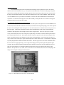
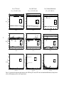
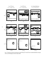
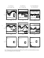
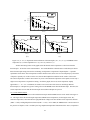
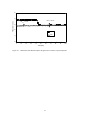
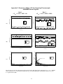
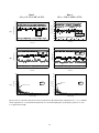
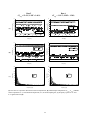
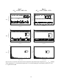
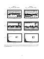
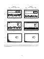
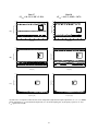
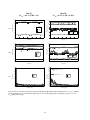
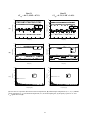
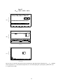
Figure 5-6. Evaporator outlet temperature signal comparison at low LMF during TXV control, MXV control, and simulated maldistribution (a) during the entire
run, (b) at 40Hz sampling rate, and (c) in the frequency domain