1
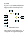
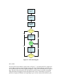
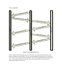
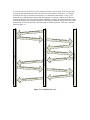
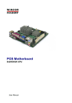
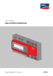
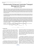
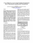
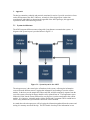
3. Approach
The design constraints, technical and practical, mentioned in section 2, provide an exclusive focus
on the development of the ADCI. However, an analysis of the design aspect is taken into
consideration, individually, to determine the approach of the ADCI prototype; this approach is
explained in detail in the following sections.
3.1
System Architecture
The ADCI integrates different sensors along with a long distance communication system. A
diagram of the system layout is provided below in Figure 3.1.
Figure 3.1: System layout for the ADCI
The microprocessor is the central piece of hardware in the system, collecting the information
received from the different sensors, logging that information, and sending it on to the cellular
module. In the best case the temperature sensor and GPS would be completely separate from the
rest of the system; allowing for them to both be easily replaced later on. The temperature sensor
follows this ideal, but the current GPS unit for cost purposes is on the same board as the cellular
module. It is; however, isolated from the cellular module and if a separate GPS is needed later it
can be easily added to the system and the current one can be disabled.
As stated above the microprocessor will be logging the information gathered from the sensors and
storing it in memory stored off the chip. This will enable a back-up of the information in case
any of it is not properly transmitted. There are many different storage devices that can be used
and these are discussed further on.
The information gathered in the microprocessor is buffered and then sent onward to the cellular
module at one minute intervals. The cellular module is able to interpret these messages and turn
them into text messages which can then be sent to either another cellular device or to an e-mail
address where the information can be gathered by a base station computer. If there are any
problems with sending the data a message can be relayed back to the microprocessor to have it
make a note of the failure to send; thus allowing data which failed to transmit to be quickly found
on the accompanying data logger.
3.2
3.2.1
Hardware
Microprocessor
The microprocessor has many tasks in the ADCI. It must read on data from the different sensors
and create buffers for this data. At regular intervals it will store the data it has collected on the
attached data logger, as well as send the current sensor readings to the cellular module at one
minute intervals. The microprocessor must also be able to identify when the cellular module has
an error sending and ensure that the data is not lost.
There are many different types of microprocessors, but due to previous knowledge only the PIC
family was researched for this task; specifically the PIC24HJ32 using the mini-Bully and the
PIC18 using the PICAXE microprocessor system. Both of the microprocessors will work for the
ADCI and the decision on which was used was not based on any physical parameters. The team
leader has worked with the PIC18 and PICAXE system before and is more comfortable with it
than the PIC24. The main embedded programmer in the group has worked with both the PIC18
and the PIC24 with mini-Bully before, so both were quite familiar. In the end the PIC18 with
PICAXE system was chosen due to the group overall being more comfortable with it.
3.2.2
Sensors
The ADCI has to be capable of measuring location, altitude, speed, and temperature. In order to
meet these needs, several sensors are required.
The most important measurement for the ADCI is location. Location is measured using a GPS
module that is incorporated within the Terminus cellular module. The Terminus cellular module
was chosen for the ADCI because of its capability to measure GPS data and communicates as
explained in section 3.2.3.
The next sensor on the ADIC is the temperature sensor. There are many types of temperature
sensors available. The first sensor consider for the ADCI was a liner LM34. The LM34 is a three
wire IC sensor in a TO-92 package. This sensor is inexpensive and is easy to interface with the
microcontroller. The LM34 has a temperature range of -45°C to 148°C providing a suitable range
for the ADCI [1]. After consulting with an experienced professor, it was determined the LM34
would not be the most suitable choice for the ADCI. Since the LM34 is a linear type temperature
sensor, operating it at low temperatures will cause electrical noise over the signal wire. This will
cause the microcontroller to read erratic voltages into the ADC yielding erroneous data. Since the
balloon will be reaching altitudes of up to 10 miles, the ADCI will encounter very low
temperatures causing the LM 34 to give incorrect data.
The current solution to replace the LM34 is the DS18B20 temp sensor. The DS18B20 is a
programmable resolution one-wire digital thermometer. The DS18B20 temp sensor can be read
using 12bit resolution where as the LM34 could only be read using 10bit resolution. The
increased resolution means the sensor is more accurate. The DS18B20 does not just change its
voltage as a function of temperature, it also has a built-in buffer and hi and low temperature
triggers. This enables temperature ranges to be set within the sensor itself to notify of an over or
under temperature situation. Since the IC has a buffer, it contains the received information until
the microcontroller accesses it. A block diagram of the DS18B20 is shown below in figure 3.2.
Figure 3.2: Block diagram of the DS18B20 thermometer [2]
The thermometer can be used as a one-wire sensor, meaning that only one wire is needed to read
and power the unit. There is a built in parasitic capacitor that the sensor pulls power from while
the microcontroller is reading the data. The DS18B20 has a temperature range of -55°C to 125°C.
This will satisfy the temperature requirement for the ADIC. This sensor will be implemented on
the ADCI.
The ADCI is designed to allow for added sensors in the future. The possibility of having more
sensors added allows the user to customize the ADCI to their particular needs. It would be easy to
incorporate a barometric pressure sensor or some accelerometers to add to the collected data. This
data can also be processed by the microcontroller, data logged and wirelessly transmitted just as
all the current sensors are capable of.
Other data collection devices may include an onboard camera. A camera that has remote
triggering capability could be triggered by the microcontroller to take pictures periodically. The
pictures cannot be sent through wireless communication or stored in the ADCI’s data logging
module. All pictures are held in the camera’s internal memory where the user can access them
once the package is on the ground.
3.2.3
Data Logging
As mentioned above, the ADCI requires data logging capability. Due to the possibility the
cellular module fails to send a message, the current sensor data must be stored for the user to
access after flight. The microcontroller gathers the data from all the sensors, including GPS
location, and has to store it all someplace. The microcontroller has enough non-volatile memory
to store a few samples of the sensor data but not enough to store all data recorded in a two hour
flight. In order to retain all measured data, a data logger is required. To meet the data logging
requirements for the ADCI, several criteria must be met. The most important requirement for the
data logger is it has enough storage space to hold all data collected during a two hour flight. The
second is the type of data logger used must be able to interface with the microcontroller. The third
requirement is that the data logger be removable from the ADCI. This will allow the user to
retrieve the data once the ADCI is on the ground without any support from the ADCI unit. The
final requirement for the data logger is cost. Data loggers have a wide range of cost so a
reasonably priced data logger that meets all requirements is desirable for the ADCI.
The first step to finding a data logger is determining the amount of storage capacity required. For
the ADCI, the collected data will be stored once every minute over a two hour period of time
adding up to a total number of 120 messages. The amount of data accumulated for one flight is
found by using equation 1 shown below.
[1]
The GPS, temperature and other sensor data measured by the microcontroller, is estimated to
be140 bytes. Having the estimated number of bytes per message and the total number of
messages, the data storage space required is calculated as shown below using equation 1.
After determining the number of bytes required for a two hour flight, we have narrowed down the
total choices of data storage to a few that can meet the needs of the ADCI.
The easiest and cheapest way to store data from the microcontroller is by using an Electrically
Erasable Programmable Read-Only Memory IC or (EEPROM). An EEPROM is an integrated
chip that is used for non-volatile data storage. The microcontroller can read and write data to an
EEPROM as need without any problem. It provides adequate storage space but it is not a
removable device. If an EEPROM was used, the user would be required to have the ADCI
connected to a computer in order to extract the data that is stored on the IC. This method is not
practical because of the added difficulty for the user to retrieve data.
Another data storage device is a secure digital card or (SD card). SD cards are very popular in
many electronics that stored data such as, digital cameras and cell phones. SD cards provide data
storage ranging from a few MB ranging to 32GB; greatly exceed the 16.8KB required by the
ADCI unit. A disadvantage of the SD card is cost. The SD cards themselves are not expensive but
the card slot that is used to read and write to the SD card itself is. This would accrue added cost to
the ADCI package but would also make it more user friendly. Another disadvantage is, it is more
complicated to read and write to an SD card using the microcontroller. Although it is more
expensive and more complicated to interface, it is worth the tradeoff to have the data stored on a
removable more user friendly data storage medium.
Another data storage possibility is adding a USB port to the ADCI that will allow a jump drive to
be inserted to store data. Jump drives are inexpensive, readily available and widely used for
portable data storage. The storage capacity of jump drives range into the hundreds of GB,
providing more than enough storage space for the ADCI application. USB breakaway boards are
available providing an interface for the microcontroller to read and write to an inserted jump
drive. This method of data storage will be the most portable and the least complicated within the
price range for this project.
3.2.4
Communication
The cellular module is the chosen device to communicate the data, primarily because of its speed
to transfer data. Also, the procedure to set up the link between two peers, a computer and the
ADCI, is not time consuming. The connection for the Cell module is made towards the internet to
achieve a point to point connection between the two.
Think of the cellular module as a cell phone whereas a phone number is not needed; the
connection is done with AT&T wireless. This approach has the advantage of shifting the control
of the application through the modem directly on a cell phone tower, making it readily accessible
from the ADCI to the computer via text messaging.
The connection is billed on the amount of data exchange (number of text messages transferred)
and not on the time spent connected, or the distance the module has to cover. This makes it
plausible for the module to always stay connected and ready to receive/send data on demand.
Shown below in figure 3.3, is the block diagram of the Cell module.
FIGURE 3.3: Cellular module block diagram [3]
Above in figure 3.1, there is a RS-232 block; this is where the communication will come from
when the cell module is active. For a clear picture of where the RS-232 connects on the cell
module, see figure 3.4 shown below.
Figure 3.4: Serial Interface plug [3]
The RS-232 connects to the computer so that the messages being communicated from the ADCI
will get transferred to its correct location.
The Embedded interface is a 50 pin dual row header that allows the ADCI to access many of the
available ports and features of the cell module through a single interface [3]. Figure 3.5 shows the
connection points.
Figure 3.5: 50 pin dual row header [3]
As shown above in figure 3.5, the connector is located on the bottom of the unit. To aid the ADCI,
the interface divides up into two groups: General Purpose I/0 (input and output) interface, and
GPS Receiver interface. This enables the module to be accessed through a single port.
3.2.5
Power Supply
ADCI uses Lithium Sulfur Dioxide (LISO2) Batteries to supply energy. Each battery has a
voltage of 2.9 V, and putting 4 of them in series allow approximately 12 V for the ADCI. The
LISO2 provide the ADCI with mobility, portability, and reliability. The LISO2 batteries are
decided due to the power needed for the ADCI power consumption it uses. Lead acid, nickel
metal-hydride, and lithium-ion are three types of batteries that are cable of producing the voltage
for the ADCI. Lead acid battery is an inexpensive but heavy battery that could form a memory; a
memory in a battery is caused by overcharging of the battery, which will diminish the battery life
overtime [4]. With nickel metal-hydride battery, forming of memory and weight are not an effect,
but it is expensive. Lithium-ion battery has less weight and no development of memory, and it is
said to have a better life span when introduce to cold weather. With those effects, the LISO2 is
chosen for the ADCI.
3.3
Software
Software for the ADCI consists of C code to control the microprocessor and Python for the
cellular module as well as the GUI. The microprocessor programming allows it to get raw data
from the sensors and convert it into a format usable by the cellular module. The cellular module
coding is then used to convert the data into a text message which can be sent to any preselected.
The GUI’s code will poll the e-mail account and take any new messages and display them in an
easy to read format.
3.3.1 Microprocessor
The microprocessor cycles through each of the sensors, reading new information off them into
buffers. In the case of the GPS it chooses the middle value from the buffer and stores it. For the
other sensors the data will be averaged and this number is stored. Every minute the
microprocessor takes the current sensor data and sends it on to the cellular module and also saves
a record of the sent data in the data logger. After sending the data to the cellular module the
microprocessor waits to see if the message can be sent; if not then it makes a note of this in the
data logger before starting to read from the sensors again. The state diagram of this process can
be seen in Figure 3.6 below.
Power ON
Stage 0
NO
Send timer
YES
Send Data to Cell
Module
Stage 5
Read Temp
Sensor
Stage 1
Successful
Read GPS
Stage 2
NO
Record Failure
Stage 6
YES
Log Sent Data
Stage 7
Read Sensor 2
Stage 3
Log Recorded
Data
Stage 4
Figure 3.6: Microprocessor State Diagram
3.3.2 Cellular Module
As of this moment there is no code of our own in the cellular module. There are built in
commands to take input and send it as a text message to a phone number or e-mail address. There
may need to be some code added after some testing. For instance we may want it to send the data
to a different e-mail in flight by sending a pre-selected message to the module. Also, for cases
where the message was unable to be sent from the ground it may be possible to queue the
message to be re-sent when in contact range without input from the microprocessor.
Power ON
Stage 0
Get E-mail Input
Stage 1
Check Today’s
Flight Data
Stage 2
Any Data
Yes
Pull Data Into GUI
Stage 3
NO
Wait 1
minute
YES
Check for New
Data
Stage 4
NO
New Data
Figure 3.7: GUI State Diagram
3.3.3 GUI
The current GUI state machine is shown above in Figure 3.7. On startup the GUI is supplied an
e-mail address by the user where the data is being sent. The GUI then polls the e-mail account
for any data from the current day’s flight and displays it along with a timestamp for each piece of
data. After the initial start-up the GUI will check the e-mail account every minute for updated
flight information and append it to the information on the screen. In the future it may also be
possible to display the GPS data on Google Maps to give an idea visually of the balloon’s path.
3.3.4 Usage Cases
Provide C
orrect E-m
ati
Inform
ail Address
on
Informatio
n
Dis
ta
ght Da
ent Fli
rr
u
C
plays
Graphical User Interface (GUI)
User
Requests
Today’s E
reques
Sends
Requests
Dis
Flight
a
ted E-m
New E-m
reques
Sends
pdated
plays U
-mails
ils
E-Mail Client
R eq
d d r e ss
-mail A
u e st E
ails
a
ted E-m
ils
Data
Figure 3.8: GUI Sunny Day Case
Figure 3.8 above shows the sunny day case for the GUI. On start-up it asks the user for e-mail
address information to poll for data. The user provides information causing the GUI to poll the email account for any e-mails from the current day. The GUI then displays this information for the
user. Every minute after that, the GUI polls the e-mail account for any new messages and
updates the information for the user.
A rainy day case for the GUI occurs if it cannot access the e-mail account. If the user provides
incorrect e-mail information the GUI will first try to connect to the e-mail server. If it cannot
connect the first step is to check to ensure there is a connection to the internet. If not, it will
inform the user and ask them to ensure that the computer is connected. Otherwise, if there is a
connection then the GUI will tell the user that something is wrong with connecting to the e-mail
account and requests new account information. After this, provided the user gives correct e-mail
information, the GUI will poll the e-mail and return to normal operation. This case is outlined
below in figure 3.9.
rmation
l Address Info
Request E-mai
o
Request New
Provide Correct
E-mail Address
Info
ne
Could Not Con
ct
Check Internet
Connection
ec
Internet Conn
tion Okay
Requests Toda
y’s E-mails
Sends Reques
nt Flight Data
Displays Curre
Figure 3.9: GUI Rainy Day Case
ted E-mails
E-Mail Client
s Info
E-mail Addres
Requests Toda
y’s E-mails
Graphical User Interface (GUI)
User
Provide Incorre
ct E-mail Addres
s Inf
During a sunny day the microprocessor is constantly reading new data off of the attached sensors
and occasionally sending the data to the data logger. Once every minute the microprocessor
creates a data package containing most recent sensor information and sends it onward to the
cellular module. It then waits for the cellular module to say that the message was sent
successfully before storing the package and resuming its reading of the sensors. The normal
operation can be seen below in figure 3.10.
or Data
Data
Sensors
Sends Sensor
Log Data
MIcroprocessor
Data Logger
Requests Sens
Log Data
or Data
Sends Sensor
Data
Send Data Pack
ag
e
nt Data Packag
Successfully Se
Log Data Pack
age
Figure 3.10: Microprocessor Sunny Day Case
e
Cellular Module
Requests Sens
Send Data Pack
age
nd
Could Not Se
Log Data Pack
age
Send Data Pack
ag
e
nt Data Packag
Successfully Se
e
Cellular Module
age
Log Data Pack
Microprocessor
Data Logger
Log Error
d Package
Request Faile
Send Failed Pa
ckage
Send Data Pack
age
nt Data
Successfully Se
Package
Figure 3.11: Microprocessor Rainy Day Case
Above in figure 3.11 the rainy day case for the microprocessor can be seen. The data package
that is sent to the cellular module returns a failure to send notice. In this case the microprocessor
must make a note along with the logged data that there was a problem sending the package. It
then returns to normal operation until a data package is successfully sent. When this occurs, and
the microprocessor receives confirmation that it was sent successfully, a request is sent to the data
logger for the failed package from earlier and resends that package onward to the cellular module
in an effort to transmit any failed data.
Reference
[1] National Semiconductor Datasheet, LM 34, precession Fahrenheit temperature sensor.
[Online]. Available: http://pdf1.alldatasheet.com/datasheet-pdf/view/8853/NSC/LM34.html
[2] Dallas Semiconductor Datasheet, DS18B20, Programmable Resolution 1-wire digital
thermometer. [Online]. Available: http://www.rev-ed.co.uk/docs/ds18b20.pdf
[3] Janus Remote Communications Datasheet, Terminus GSM864Q Hardware User Manual.
[Online]. Available: http://www.janus-rc.com/pr/GSM864Q_user_guide.pdf
[4] [Online]. Mississippi State University, Senior Design Archives. Available:
http://www.ece.msstate.edu/courses/design/2008/pwrsupply/home.html