1
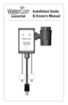
ZWCFS100 Wireless Water & Freeze/
Temperature Sensor: User Manual
Thank you for purchasing this Wireless Water & Freeze / Temperature Sensor. This product will provide you with peace of
mind and the protection you expect. Leaking pipes, corroded water heaters, fixtures in bathrooms and laundry rooms, refrigerator
drip pans, etc. can all cause water damage. The ZWCFS100 is a Z-Wave™ enabled device that will send a water alert
on your Z-Wave™ network. Devices performing other functions and from other manufacturers can also be part of your
Z-Wave™ network and can act as repeaters to extend your network range.
Functionality
The ZWCFS100 senses when water is detected and will also provide
a Z-Wave™ alarm signal when the temperature drops below a low
temperature setpoint or rises above a high temperature setpoint.
The ZWCFS100 functionality is based on wireless (RF) transmissions.
Any wireless transmission can be subject to RF interference and,
although unlikely, this interference may cause the device to not
operate as intended. The ZWCFS100 must not be used in life support
and/or safety applications.
Information provided in this manual is for your convenience and may be
superseded by updates. The specifications and this manual are subject
to change without notice. It is your responsibility to ensure that the
ZWCFS100 meets your specifications.
Inclusion in (adding to) a network: 1) Set up the inclusion mode at the
controller; 2) Inclusion and exclusion are always done at normal transmit
power mode.
Exclusion from (removing from) a network: Set up the exclusion mode
at the controller.
Associations: Once in a network, a controller can be used to associate the
ZWCFS100 with other devices in the Z-Wave™ network, such as a light or
another remote audible alarm. Refer to your controller’s documentation
on how to associate ZWCFS100 with another device in your network.
The ZWCFS100 supports three association groups with a maximum of
5 devices in each group. Basic Set commands are sent at 30-minute
intervals to the associated groups while alarms are active.
• A Basic Set Command is sent to the associated nodes, if any,
assigned to Group1 to indicate that EITHER a Water Alarm OR
Heat Alarm (under or over temperature) is active.
Specifications
Power:
Two AA alkaline batteries
Battery Life:Calculated to be 1 to 2 years with no alarms and
default Z-Wave™ network settings
Frequency Range:
908.4MHz (US); 868.4MHz (EU)
Distance Range:Max 100 ft line of sight in unobstructed
environment
Product Size (LxWxD):
3” (76 mm) x 2.1” (53 mm) x 1.1” (30 mm)
Product Weight:
0.24 lb (109 g)
Program Switch for
Inclusion or Exclusion
Operating Temperature: -10˚C (14F) to +70˚C (158F)
Reported Temperature:Reported temperature is at the device and has
a +/- 2˚C accuracy
System Requirement:
Any Z-Wave™ enabled network and controller
Using the ZWCFS100 in a Z-Wave™ Network
• The switch is used for including or excluding the ZWCFS100 in a
Z-Wave™ network.
• Refer to your controller’s User Manual for specific details on network
inclusion, exclusion, and association.
DynaQuip Controls • 10 Harris Industrial Park • St. Clair, MO 63077
Tel. 800-545-3636 • Fax. 636-629-5528 • www.watercop.com
Made in the USA
Products that speak Z-Wave
work together better.
TM
PN 192341
• A Basic Set Command with value = 0xFF is sent to the associated
nodes, if any, assigned to Group2 to indicate that a Water Alarm is
active. When the Water Alarm is cleared by drying the contacts,
one additional report with value = 0x00 is sent.
• A Basic Set Command is sent to the associated nodes, if any,
assigned to Group3 to indicate that a Temperature Alarm (over
or under temperature) is active. When the Temperature Alarm is
cleared due to temperature change, one additional report with
value = 0x00 is sent.
Node Info / Keep-Alive: While not in a network, the ZWCFS100 will send
the Z-Wave™ Node information frame when the switch is briefly pressed.
This is primarily used for inclusion as described above. The node
information frame will also be sent while in network when the switch
is pressed and held for 2 seconds. In either case, the ZWCFS100 will
‘stay awake’ for approximately 30 seconds after this to allow time for
configuration commands from the controller.
Wakeup Notification: The ZWCFS100 will wakeup and send a notification
every 4 hours (default) to allow a controller to query and update the
status of the device. A brief switch press while in network will also
cause the ZWCFS100 to wakeup and send a notification. The device
stays awake for 5 seconds during this time or longer if communicating
with the controller.
Choosing a Mounting Location
The ZWCFS100 is suitable for use in dry, interior locations only. Avoid
placing the device close to a metal frame, or other metal enclosures that
may affect RF range. Place the device so that any leaks that may occur
will not drip directly on the device.
Recommended ZWCFS100 uses: Under Sink, Next to Sump Pumps, Water
Heaters, Laundry Room, Bathroom Floor, Storage Area, Garage, Utility
Sink, Vacation/Recreation homes, Boats, etc.
During an Alarm
If water is detected at the monitoring location, the unit will sound an 82
decibel, audible alarm and will send an alert message to the Z- Wave™
network (if included in the network already). Pressing and holding the
button for 2 seconds will clear the Water Alarm. If freezing conditions are
detected, no audible alarm will sound but an alert message is sent to the
Z-Wave™ network (if included in the network). The type of alert message
depends on how the ZWCFS100 is configured. If associations are
configured, Basic Set messages will be sent as described above under
Associations. If Water or Heat Alarms have been configured (via Alarm
Command Class V2 Set commands), then the ZWCFS100 will send alert
messages to the Node ID that configured the alarm. Association alert
messages and Alarm alert messages may both be configured and sent.
Drying the sensor contacts will clear the Water Alarm. If an over/under
Temperature Alarm occurred and the Temperature Alarm conditions are
no longer present, an ‘alarm clear’ message is also sent to the Z-Wave™
network (if included in the network).
Also, depending on your Z-Wave™ controller, it is possible to receive a
remote alert. For example, with some gateway controllers, you can
receive an email or cell phone text message when an alarm is activated.
Depending on your specific controller’s capabilities you will be able to
remotely check the status of any ZWCFS100 in your network.
DynaQuip Controls • 10 Harris Industrial Park • St. Clair, MO 63077
Tel. 800-545-3636 • Fax. 636-629-5528 • www.watercop.com
Testing the ZWCFS100
Moisten a paper towel and place over both of the small metal pads on the
water sensor until you hear the audible alarm sound. The water alarm may
take up to 4 or 5 seconds before it sounds. If the alarm fails to sound, your
battery may be old or dead or incorrectly installed, the sensor may not be
moist enough, or the water sensor may be damaged. If you do hear the
audible alarm, remove the moistened paper towel, clean the small metal
pads of any water residue, and hold the button for 2 seconds to clear the
alarm. You can then add your water alarm to any Z-Wave™ enabled
network and controller. Examples of Z-Wave™ controllers can be found
on the DynaQuip website (www.DynaQuip.com).
Battery / Low Battery
The ZWCFS100 will send an alert on the Z-Wave™ network at regular
intervals when it detects a low battery condition. In addition, it will
periodically sound an audible ‘chirp’. Your controller may be able to be
configured to monitor the device’s wake up notifications. If these stop,
then this might also be an indication that the battery has died or that
transmissions from the ZWCFS100 are no longer being received. After a
water leak, please ensure that there is no moisture in the device and
around the battery. Do not install batteries that appear damaged or
unsealed. When replacing batteries, the water seal may be broken around
the screws. After screwing the parts back together, the use of some
sealant, such as silicone caulk, around the screws is recommended.
Configuring the ZWCFS100
The high and low temperature setpoints in the ZWCFS100 can be
configured. The low temperature setpoint must always be set at least
two degrees below the high temperature setpoint. The low temperature
setpoint cannot be set less than –10˚C and the high temperature setpoint
cannot be set greater than 70˚C. The temperature setpoints can be
configured via a ‘smart’ controller after inclusion; details are provided
in the technical appendix.
Temperature Reports
If your controller sends the wakeup interval set command, the controller
will also become the Wakeup Master node. The ZWCFS100 will
automatically send temperature reports to this Wakeup Master node
within a half hour of a 1˚C change in temperature.
FCC Compliance Statement
This device complies with Part 15 of the FCC Rules. Operation is subject to
the following two conditions:
1. This device may not cause harmful interference, and 2. This
device must accept any interference received, including
interference that may cause undesired operation. Contains
Transmitter Module FCC ID: XCT-Z3US
FCC Warning (Part 15.21). Changes or modifications not expressly
approved by the party responsible for compliance could void the
user’s authority to operate the equipment.
Made in the USA
Products that speak Z-Wave
work together better.
TM
PN 192341
FCC Interference Statement (Part 15.105 (b)). This equipment has
been tested and found to comply with the limits for a Class B
digital device, pursuant to Part 15 of the FCC Rules. These limits
are designed to provide reasonable protection against harmful
interference in a residential installation. This equipment generates
uses and can radiate radio frequency energy and, if not installed
and used in accordance with the instructions, may cause harmful
interference to radio communications. However, there is no
guarantee that interference will not occur in a particular installation.
If this equipment does cause harmful interference to radio or
television reception, which can be determined by turning the
equipment off and on, the user is encouraged to try to correct
the interference by one of the following measures:
- Reorient or relocate the receiving antenna.
- Increase the separation between the equipment
and receiver.
- Connect the equipment into an outlet on a circuit different
from that to which the receiver is connected.
- Consult the dealer or an experienced radio/TV
technician for help.
Industry Canada Statement per Section 4.0
of RSP-100
The term “IC:” before the certification/registration number only signifies
that the Industry Canada technical specifications were met.
Section 7.1.5 of RSS-GEN. Operation is subject to the following two
conditions: 1) This device may not cause harmful interference, and 2) This
device must accept any interference received, including interference that
may cause undesired operation.
From section 5.2, RSS-Gen, Issue 2, June 2007 Equipment Labels:
Contains IC: 8156A-Z3X
From section 7.1.1 RSS-Gen, Issue 2, June 2007
a) The host device, as a stand-alone sensor without any separately
certified modules, complies with all applicable Radio Standards
Specifications.
b) The host device and all the separately certified modules it
contains jointly meet the RF exposure compliance requirements of
RSS-102AA, if applicable.
c) The host device complies with the certification labeling
requirements of each of the modules it contains.
Europe
The ZWCFS100 module has been certified for use in European countries.
Test standard: ETSI EN 300 328 V1.7.1 (2006-10)
The Waste Electrical and Electronic Equipment
(WEEE) directive (2002AA/96/EC) was approved by
the European Parliament and the Council of the
European Union in 2003. This symbol indicates that
this product contains electrical and electronic
equipment that may include batteries, printed
circuit boards, liquid crystal displays or other
components that may be subject to local disposal
regulations at your location. Please understand
these regulations and dispose of this product in a
responsible manner.
DynaQuip Controls • 10 Harris Industrial Park • St. Clair, MO 63077
Tel. 800-545-3636 • Fax. 636-629-5528 • www.watercop.com
Limited Warranty
DynaQuip Controls Corporation, 10 Harris Industrial Park, Saint Clair,
Missouri 63077, warrants its WaterCop electric valve actuator and
electronic sensor and electronic system control components against
defects in material and workmanship for a period of two (2) years from the
date of original shipment. DynaQuip Controls warrants its WaterCop brass
ball valve mechanical component against defects in material and
workmanship for the life of the component. In the event that such defects
appear within the warranty period, DynaQuip Controls will, at its option,
and upon written notification thereof and substantiation that, the
product(s) have been stored, installed, maintained and operated in
accordance with DynaQuip’s recommendations and standard industry
practice, repair or replace the product without charge. This warranty shall
be invalidated by any abuse, misuse, misapplication, improper installation,
modification, or disassembly at any place other than the point of original
manufacture. This shall constitute the exclusive remedy for breach of
warranty, and DynaQuip Controls shall not be responsible for any
incidental or consequential damages, including, without limitation,
damages or other costs resulting from labor charges, delays, vandalism,
negligence, fouling caused by foreign material, damage from adverse
water conditions, chemicals, weather, or any other circumstances over
which DynaQuip Controls has no control. DYNAQUIP CONTROLS MAKES
NO OTHER WARRANTIES EXPRESS OR IMPLIED EXCEPT AS PROVIDED
BY THIS LIMITED WARRANTY.
The seller does not represent that the product; will prevent any property
loss by sudden or accidental discharge of water from plumbing systems
into living area of a residential dwelling; may not be compromised or
circumvented; or that the product will in all cases provide adequate
warning or protection. Buyer understands that a properly installed and
maintained automatic water shut-off system may only reduce the risk of
a sudden and accidental water loss event resulting in significant water
damage and is not insurance or a guarantee that such will not occur or
that there will be no personal injury or property loss as a result.
CONSEQUENTLY, SELLER SHALL HAVE NO LIABILITY FOR ANY
PERSONAL INJURY, PROPERTY DAMAGE OR OTHER LOSS BASED
ON A CLAIM THE PRODUCT FAILED TO TURN OFF WATER SUPPLY OR
GIVE WARNING OF A POTENTIAL WATER LOSS EVENT. HOWEVER, IF
SELLER IS HELD LIABLE, WHETHER DIRECTLY OR INDIRECTLY, FOR
ANY LOSS OR DAMAGE ARISING UNDER THIS LIMITED WARRANTY
OR OTHERWISE, REGARDLESS OF CAUSE OR ORIGIN, SELLER’S
MAXIMUM LIABILITY SHALL NOT IN ANY CASE EXCEED THE ORIGINAL
PURCHASE PRICE OF THE PRODUCT, WHICH SHALL BE THE COMPLETE
AND EXCLUSIVE REMEDY AGAINST THE SELLER. This warranty gives
you specific legal rights, and you may also have other rights which may
vary from state to state. No increase or alteration, written or verbal, to
this warranty is authorized.
DynaQuip Controls Corporation reserves the right to change or
improve the design of any DynaQuip Controls manufactured product
without assuming any obligations to modify product previously
manufactured or sold.
Made in the USA
Products that speak Z-Wave
work together better.
TM
PN 192341
TECHNICAL APPENDIX
BATTERY STATUS
MANUFACTURER ID 0x0084
PRODUCT ID varies
• Battery level percentage estimated based on number of Wakeup1’s
(see below) since battery insertion
PRODUCT TYPE ID 0x0063 (US) 0x0061 (EU)
• In addition, battery voltage readings can trip the low battery state
DEVICE CLASS Generic Type Sensor MultiLevel, Specific Type
Routing Sensor Multilevel
COMMAND CLASSES SUPPORTED
(in addition to COMMAND_CLASS_BASIC)
COMMAND_CLASS_ALARM_V2
COMMAND_CLASS_WAKE_UP_V2
COMMAND_CLASS_CONFIGURATION
COMMAND_CLASS_ASSOCIATION
COMMAND_CLASS_BATTERY
COMMAND_CLASS_MANUFACTURER_SPECIFIC
• Low battery report (Battery Command Class) every approx.
30 minutes after low battery becomes active, and will periodically
sound an audible ‘chirp’
WAKEUPS
• Wakeup1: Power saving design wakes up every 4 seconds to test water
and freeze sensor
• Wakeup2: Once every approx. 4 hours (default) device wakes up to send
a notification either to a wakeup node or broadcast. The device stays
awake for approx. 5 seconds or while communicating with a controller.
Sensors are not checked during this time.
COMMAND_CLASS_VERSION
• The Wakeup node is the node configured to receive the Wakeup
Notification command. This is set in the ZWCFS100 by the
Wakeup Interval
WATER ALARM
• Set command and is typically the Controller node. Only one value for the
wakeup interval, the default interval of 0x003840 (4 hours), can be set.
• Sampling every 4 seconds
MULTILEVEL SENSOR
COMMAND_CLASS_SENSOR_MULTILEVEL
• Z-Wave™ transmissions (every approx. 30 minutes while alarm is active):
‘Basic Set’ with Value = 0xFF sent to associated nodes in Group 1 and/or
Group 2 and/or an Alarm Command Class V2 Water Leak Report (Event =
Water Leak Detected, Unknown Location, 0x02AA with Alarm Level =
0xFF. What is sent depends on whether associations are configured
and/or Water Leak Alarm is enabled with a non-zero destination
• Node ID (see Alarm Factory Default State under OTHER below)
• Audible will sound
• Multilevel Sensor Report sent with current Temperature (Degrees C)
in response to Multilevel Sensor Get command
• Unsolicited Multilevel Sensor Report sent to Wakeup Node within
30 minutes of a 1 degree temperature change (if Wakeup node is
set); filtering is applied to avoid ‘oscillating’ report transmissions and
conserve battery life; transmission is independent of a Wakeup
Notification
• Alarm Command Class V2 Get (Sensor Type = 0x05, Water Leak) can
be used to request water alarm state
CONFIGURATION
• When water alarm is no longer active, sends ‘Basic Set’ with
Value = 0x00 to association nodes as above and/or Alarm Command
Class Water Leak Report (Unknown Event, 0xFE) with Alarm Level = 0x00
• Parameter 1 sets Low Temperature Trigger Point (degrees Centigrade,
1 signed byte, Default = 4)
UNDER-TEMPERATURE / OVER-TEMPERATURE ALARM
• Sampling every 4 seconds with averaging algorithm
• Parameter 2 sets High Temperature Trigger Point (degrees Centigrade,
1 signed byte, Default = 70)
KEEP-ALIVE
• Sensor has an accuracy of approx. +/-2˚C. Default alarm trigger points
set at approx. 4˚C and 70˚C
• Switch activated causes 30 sec RF receiver-on time intended for
Controller configuration after network inclusion
• Z-Wave™ transmissions (every approx. 30 minutes while alarm is active):
‘Basic Set’ with Value = 0xFF sent to associated nodes in Group 1 and/or
Group 3 and/or Alarm Command Class V2 Heat Report with Alarm Level =
0xFF and Event = [Overheat Detected, unknown location, 0x02AA or
Underheat Detected, unknown location, 0x06]. What is sent depends
on whether associations are configured and/or Heat Alarm is enabled
with a non-zero destination Node ID (see Alarm Factory Default State
under OTHER below).
• Sensors not checked during Keep-Alive time
• Alarm Command Class V2 Get (Sensor Type = 0x04, Heat) can be
used to request heat alarm state
• When temperature alarm is no longer active, sends ‘Basic Set’
with Value = 0x00 to association nodes as above and/or sends
Alarm Command Class Heat Report (Unknown Event, 0xFE) with
Alarm Level = 0x00
DynaQuip Controls • 10 Harris Industrial Park • St. Clair, MO 63077
Tel. 800-545-3636 • Fax. 636-629-5528 • www.watercop.com
OTHER
• Alarm Factory default state = Enabled; unsolicited alarm reports
(underheat, overheat, and water leak) will be sent to Node 0x01 (after
inclusion)
• This Node ID can be changed via the Alarm Set Command (Alarm
Command Class V2)
• All Network Inclusions / Exclusions are at normal power levels
• Up to 5 nodes allowed in each association group
• Basic Report sent in response to a Basic Get with value equal to
Multilevel Sensor Type (Temperature, 0x01)
• Built with Z-Wave™ SDK 4.51
Made in the USA
Products that speak Z-Wave
work together better.
TM
PN 192341