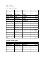
1
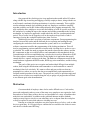
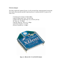
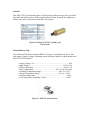
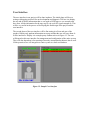
RFID Employee Access System
Project Proposal
Fetah Basic
Ken Dean
April 25, 2008
Introduction
Our proposed idea for this project is an application that would utilize RF readers
along with RF tags in tracking and logging of hourly employee hours; along with this we
would control a mechanical locking mechanism via wireless commands. This would be
used to substitute manual clock punching in and out. Employees could have small RF
tags that would be read by RF readers and perform the hour logging automatically. The
tags would also allow employees access into the building of work or specific area inside
the workplace by reading the tags at the entrance and sending commands to the locking
mechanism. As employees approach it would unlock the door for a predetermined time
period. This of course can be logged as well so the employer keeps track of who is
entering or leaving the workplace and the time when it occurs.
With this project there are plenty of software components. From programming the
interface between the reader and the backend device to parsing and reading the tags,
configuring the reader door lock microcontroller system, and so on. An additional
software component would be the programming of the locking mechanism. This will
involve programming a microcontroller to interact with a locking device such as a servo
or solenoid. We would also need to program the interface between this software and the
RF components so that we would be able to send commands to this mechanical device.
Communication will be accomplished using a wireless device such as Bluetooth or WIFI.
The other software components would also be the higher-level application that would
control this flow, capture, and process the data. The hardware components would be the
actual hardware equipment the RFID reader, RFID tags, microcontrollers, and the locking
mechanism.
The goals of this project are recognize and read multiple RF tags from multiple
readers, then using this information send commands to a microcontroller to control a
mechanical door lock wirelessly. We want to collect and process this raw data in a
meaningful way where we can use the data to accomplish daily tasks automatically to
facilitate routine procedures for the users. The project may easily be split into stages and
smaller pieces as tasks to accomplish along the way to gauge our progress that will lead
to our ultimate goal at the demonstration.
Motivation
Current methods of employee time clocks can be difficult to use. Card readers,
passwords, and punch cards are some of the many ways employees are required to clock
into and out of work. Many of these devices are susceptible to a variety of problems that
make their use undesirable. In addition to the problems inherent in these methods
employees may forget to clock in or out when they arrive or depart from the work place
or may be required to wait while others are clocking in or out.
Entering or exiting the workplace may also require the use of a key, card, or other
device to gain entry. It is a logical step to combine the two and allow the worker to enter
and clock in with the same RFID tag.
Project Tasks
• Acquire a suitable RFID system.
• Acquire a suitable microcontrollers.
• Acquire a suitable solenoid to use as locking/unlocking device
• Create a RFID receiver to computer link.
• Create link between RFID system and door lock microcontroller
• Interface to employee time clock database.
Specific Task Interfaces
RFID Tag
There are various kinds of RFID tags that are available ones that only work with one
specific type of RFID reader and once that can work with several types. Usually these
tags have several programmable configurations, such as transmitting rate, ID addressing,
Site Code, etc. And other specialized tags may have various other sensors like
Temperature, Movement, etc. This is done through specialized tag programmers. The
tags we are going to get will come pre-programmed or pre-configured with ID addresses,
Site Code and transmitting rate, which will work fine for our application. Ideally we
would like to use the key fob tag for this project because of the obvious attractions of
having a tiny tag that can be attached to a key chain for employees to use easily, but the
key fob tags are one of the more expensive tags. The tag we are planning to use is one of
the most popular solid by Wavetrend which is T501 (Figure 1; source: Wavetrend) it has
a life expectancy of 3-5 years that can be detected when it is nearing end of life, it also
has tamper proofing ability, and maybe most importantly besides doing the job for us, we
can get it for free. [2]
Figure 1. T501 RFID Tag
RFID Reader
Our RFID Reader L-RX201 (Figure 2; source: Wavetrend) is best suited for a single
network set up that would consist of up to 254 (Addressing restrictions of the reader) in
daisy chain like setup (Figure 3; source: Wavetrend) but in our application we only need
one to accomplish our project and demonstration (Figure 4; source: Wavetrend). [1]
Figure 2. L-RX201 RFID Reader
Connection of reader to PC can be done via the RS232 or Left RS485 ports. We have
chosen to connect via RS232 to the PC. The network operates at speeds of 115200 baud
down to 9600 baud. Data to and from the PC must be at the same rate. These rates can be
altered when initializing the serial connection between the reader and PC. The reader has
the following interface specifications: [1]
RFID Reader Interfaces:
• Interface
Serial RS232 or RS285
• Baud
115 kB/s, 57.6 kB/s, 38.4 kB/s, 19.2 kB/s, 9.6 kB/s Selectable
• Parity
None
• Start Bit
1
• Stop Bit
1
• Data Bits
8
The Data is passed and arranged in a packet format. The reader can be individually
addressed by using one of two address techniques, or it can be set up to broadcast.
Figure 3. Reader Possible Network Setup
Figure 4. Our Single Reader Setup
We plan to use the broadcast option along with auto polling feature to get a steady stream
and sampling of RFID tags data that is transmitted. We will not be overly concerned with
data corruption or lose of packets since the data is coming continuously at a frequent
enough rate that we can wait for the next valid packet. The reader operates on a
command/response operation formatted in packet of data with error checking etc that is
included in the protocol. Data only flows in one or the other directions since we are using
a single serial port to control the communication. Here is a short list of commands
(Figure 5; source: Wavetrend): [1]
Figure 5. Command Shortlist
The Get Tag Packet command will be the most useful and most used command in our
application for the obvious reasons that we want refreshed tag information as soon as it is
available (Figure 6; source: Wavetrend). [1]
Figure 6. Get Tag Command
The data field portion of the packet looks like this (Figure 7; source: Wavetrend):
Figure 7. Data Field
The software development for the reader and central processor will be accomplished
using C-Sharp. Many times readers come available with SDKs from the manufacturer for
easy interfacing. We will have to review the SDK for our reader and make the decision to
either go with it or go with our own interface which is more the brute force way. The pros
and the cons will have to be weighted. As of now the plan is to go with our own interface
developed from scratch.
Finally the reader also has LED lights that will indicate the mode the reader is currently
in, this will help us visually identify if we are successful in setting up the reader and the
state the reader is in at any one time. This will help immensely when testing and
debugging.
Microcontroller
The wireless ARMmite (Figure 8) is a low cost single board computer that uses an
ARM7 CPU. This will provide more than adequate processing power for our application.
It will be programmed via a ZigBee 802.15 RF module with a BASIC programming
language.
• Simply Connected™ Technology
• ARM7 CPU running at 60 MHz
• Programmed via Serial interface over optional Zigbee, Bluetooth or USB
• BASIC compiler runs >10 million lines of codes/sec
• 32K Flash memory with 12K available for user code
• 8K SRAM memory with space for over 1000 user variables
• C compiler to access all 32K Flash and 8K RAM
• 24 TTL compatible digital I/O
• 8 10-bit A/D converter channels
• Onboard regulated power supply runs off 5-6V DC input
• Internal supplies of 3.3V and 1.8V
Figure 8. ARMmite wireless microcontroller.
Wireless Adapter
The XBee ZigBee RF module (Figure 9) will provide all the communication between the
door latch microcontroller and the central processor. It utilizes the 802.15 protocol for
ease of use.
• Transmit power output: 1mW (0 dBm)
• Indoor/Urban range: Up to 100 ft (30 m)
• Outdoor/RF line-of-sight range: Up to 300 ft (100 m)
• RF data rate: 250 Kbps
• Interface data rate: Up to 115.2 Kbps
• Operating frequency: 2.4 GHz
• Receiver sensitivity: -92 dBm
Figure 9. XBee® 802.15.4 OEM RF Module
Solenoid
This SMT-2551L24A solenoid (Figure 10) will provide all the necessary force to pull the
door latch and hold it in place for the required period of time. Its small size, high power,
and low cost make it the perfect solenoid for our purpose.
Figure 10. Solenoid, 24VDC, 60 ohms, pull
1-inch stroke
Solenoid Driver Chip
The solenoid will be driven using the DRV101 (Figure 11) solenoid/valve driver. The
wide range of supply voltages, operating current, and times makes it an ideal match to the
SMT-2551L24A solenoid.
• Supply Voltage, VS .............................................................................. 60V
• Input Voltage .......................................................................... –0.2V to VS
• PWM Adjust Input .................................................................. –0.2V to VS
• Delay Adjust Input ................................................ –0.2V to VS (24V max)
• Operating Temperature Range ......................................–40°C to +125°C
• Storage Temperature Range .........................................–65°C to +150°C
• Junction Temperature .................................................................... +150°C
• Lead Temperature (soldering, 10s)(2) ........................................... +300°C
Figure 11. DRV101 solenoid driver.
User Interface
The user interface in our project will be done in phases. The initial phase will be as a
testing or debugging tool used for our development and diagnosis. Will use it to display
the any and all useful information that we can such as RFID tags we see currently and
have seen. All the information for the tags: tag ID, site code ID, signal strength etc. This
will be very useful in the process of developing the final design of the project and the
user interface.
The second phase of the user interface will be fine tuning it to fit an end user of the
product. Display only prudent information necessary and that the user will care about. It
will be interactive. Display it in a simple pretty fashion such as in Figure 12. The user
will depend on this user interface for management and configuration of the entire system.
They will also depend on it for reporting of not only current data but historic data as well.
If time permits us we will integrate our entire system to a back end database.
Figure 12. Sample User Interface
Testing and Integration
Using RS232 serial port communication to connect from the PC to the RFID reader we
will initialize the current state of the reader and can use the LED indicators on the reader
to verify if we have done it successfully. Once the reader is setup and connected to the
PC we will begin reading the serial data we get from the reader and parse it for the Tag
data transmitted. Displaying this data real time in a GUI will help continuously test and
verify the data we are getting or if we are getting any data at all, and if we should be
getting data. Once this tag monitoring is established then we can proceed to
implementing processing logic to utilize this data.
Sending an address code with an open command to the microcontroller will verify that
the communication with the computer and microcontroller is working and the correct
address and instruction decoding is taking place. The door lock mechanism will tested
upon assembly with a simple program written in the microcontroller to verify the proper
operation of the unit. Sending the address with an open instruction to the microcontroller
will then test the completed link from the computer to the door lock.
Group Communication Plan
Our communication will always be via email, phone, etc. We plan to communicate
frequently to stay in tune.
We will meet weekly at 1:00pm in the CS lab WEB 130 during the spring semester.
As necessary will meet on weekends and weeknights.
Once the project officially starts we plan to meet in the summer to get things under way
and then we will arrange future meetings through our communication. Finally we will
setup a standard constant place and time to meet and work together on the project.
Schedule and Milestones
Acquisition of the RFID system and door lock microcontroller system
Implementation of the RFID system and door lock microcontroller system
Linking RFID system to time clock computer
Linking of RFID system to door lock microcontroller system
Week 1 –
Week 2 –
Week 3 –
Week 4 –
Week 5 Week 6 Week 7 Week 8 Week 9Week 10Interface
Week 11Week 12Week 13Week 14Week 15-
Acquire the RFID reader and tags (FB). Order microcontroller, door
lock
Solenoid and interface cables (KD).
Begin RFID interface (FB).
Begin work on microcontroller code (KD).
Continue work on RFID interface (FB)
Complete work on microcontroller (KD).
Complete work on RFID interface (FB).
Debug microcontroller (KD).
Build door-locking device (FB, KD).
Interface microcontroller to door lock (FB, KD).
Test door lock microcontroller assembly. (FB, KD)
Begin interfacing microcontroller assembly with RFID Central
Processor
Continue working on microcontroller assembly and RFID Central
Processor interfacing (FB, KD)
Complete microcontroller assembly and RFID Central Processor
Begin UI development to tie into clock in/out system (FB)
Complete UI development, start Debug/Testing (FB, KD)
Debug/Testing (FB, KD)
Complete the system, finish final report (FB, KD).
Demonstrate a fully functional system.
Tasks
August
RFID
Interfacing
Build UI/DB
Interface
Interface
Microcontroller
to central
system
Interface
Microcontroller
to Door Lock
Device
Build Door
Lock Device
Report
September October
Tentative Gant Char
November
December
Tasking
FetahRFID Reader/Tag interface to central processing system.
Central Processing RFID interface UI
Interface central processing system to Microcontroller Door Lock Device
Interface to Employee DB
KenKen will acquire all the parts for the door locking mechanism and
the microcontroller. He will assemble the door lock, interface it to the
microcontroller, and complete all testing on these components to verify proper
operation.
BothDebug
Test
Documentation
Risk Assessment
Common risks associated with our system will come in interfacing our various
components together to function as one system in sync. Risks such as the interfacing of
the RFID reader with central processing system. Another potential risk is going to be the
interfacing of our microcontroller to the door lock device these to components must be
able to interface to one another for our overall system to function as we want it to.
Purchasing the right microcontroller and the right door lock device with the correct specs
will be essential in accomplishing a successful interface between the two. Another risk or
challenge posed by this project is that the microcontroller besides interfacing to our door
lock device must also interface wirelessly to our central processing system. The risk here
would be the interfacing of the either the 802.11 WIFI network protocol or Bluetooth
network protocol which are both unfamiliar to us now. Again which protocol it is will
depend on choosing the correct microcontroller.
Bill of Materials
Preferred parts and suppliers.
Part
Part #
Supplier
24VDC Solenoid
SMT-2551L24AA
Jameco
Solenoid Driver
DRV101FKTWT
Wireless ARMmite
XBee Zigbee
wireless
RFID Reader
AM-WL
Digi-Key
Coridium
Corporation
Antennas
Power Supply
Power Supply
Cables
Cables
Tags
XB24-AWI-001
L-RX201
AN100 Quarter
Wave Whip Antenna
PS300 power supply
unit
PS300 power supply
cable connection
AC501 PC serial port
cable
AC502 power supply
to reader cable
(2) T501 or others
RFID Reader SDK
and other software
Digi-Key
Wavetrend &
Iautomate.com
Wavetrend
Wavetrend
Wavetrend
Wavetrend
Wavetrend
Wavetrend
Wavetrend
Total
Cost
$11.99
$7.70
$39.95
$19.00
$499.95 (Free for
us)
Included in Reader
package
Included in Reader
package
Included in Reader
package
Included in Reader
package
Included in Reader
package
$19.95 to $39.95
(Free to us)
$49 (Free to us if
needed)
$79.49
Alternative parts and suppliers.
Part
Wireless
microcontroller
Part #
RCM4400W
Development Kit
Rotary Solenoid
Solenoid Driver
Module
RFID Reader
Total
R-09-150-CCWM
PWM400
L-RX300
Supplier
Rabbit
Semiconductor
Magnetic Sensor
Systems
Magnetic Sensor
Systems
Wavetrend
Cost
$149.00
$137.18
$78.34
$69.95 (Free to us)
$364.52
Vendor List
Magnetic Sensor Systems
6901 Woodley Avenue Van Nuys, California 91406
Phone: (888) 785-9444
(818) 785-6244
Fax: (818) 785-5713
E-Mail: [email protected]
Rabbit
2900 Spafford Street Davis, California 95618-6809 USA
Phone: 1.530.757.8400
Fax: 1.530.757.8402
E-Mail: [email protected]
Coridium Corporation
PO Box 339
Tahoe Vista, CA 96148-0339
Tel: 1-800-478-9020
Fax: 1-800-478-9020
Coridium Corporation
6790 N Lake Blvd
Tahoe Vista, CA 96148-0339
Tel: 1-800-478-9020
Fax: 1-800-478-9020
Digi-Key
701 Brooks Avenue South, Thief River Falls, MN 56701 USA
Phone: 1-800-344-4539
218-681-6674
Fax: 218-681-3380
Jameco Electronics
1355 Shoreway Road, Belmont, CA 94002
Tel: 1-650-592-8097
Fax: 1-650-592-2503
Toll Free Tel: 1-800-831-4242
Fax: 1-800-237-6948
International Fax: 1-650-592-2503
Wavetrend Technologies Inc
11350 Random Hills Road, Suite 800, Fairfax, Virginia 22030
Tel: 703-934-6000
Fax: 703-934-6012
Kyle Kosinski
Tel: 703-934-6010
Stan L. Reid
Tel: 703-934-6013
Mobile: 703-599-7108
Email: [email protected]
Conclusion
Having had the time to spend this semester to research and plan this project we feel
confident with all the aspect of the project. There is little bit of inherent risk with taking
on any bigger project such as this special when it’s from initial design all the way until
finish product in a defined and relatively tight schedule. Then there is the risk of the
unfamiliarity with some of the aspects of the project and risk of interfacing the various
components. Schedule would have been a little bit tight had we just had the fall semester
to do it all, but since we plan to get started in the summer it should give us enough time
to finish everything in time handle any unexpected road block is they should come up and
if all goes well it should even give us some extra time to implement our extra features.
We are excited to get this project started and ultimately fully integrated and completed on
time to demonstrate our engineering skills.
References
[1] Wavetrend, User Manual L-RX201, Doc No: EAB-02710-00-UM
[2] Wavetrend, L-Series Product Information Sheet, Doc No: EAB-00200-04-PI
[3] www.wavetrend.com