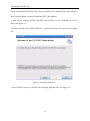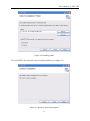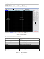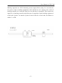
1
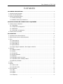
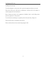
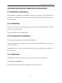
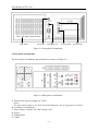
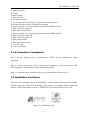
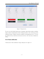
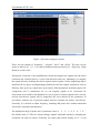
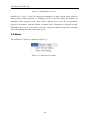
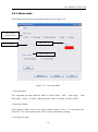
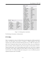
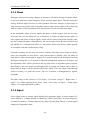
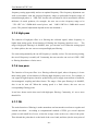
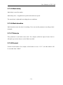
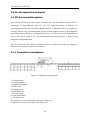
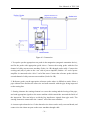
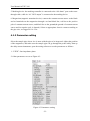
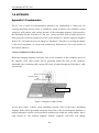
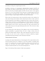
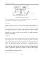
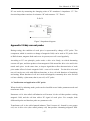
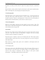
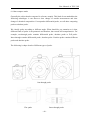
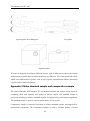
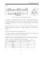
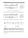
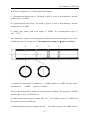
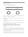
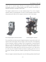
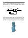
EDDYSUN
EEC-30S
USER MANUAL
EDDYSUN (XIAMEN) ELECTRONIC CO., LTD.
June, 2014
User Manual of EEC-30S
CATALOG
1.0 GENERAL DESCRIPTION ................................................................................................................... - 1 1.1 CHARACTERS OF EQUIPMENT...................................................................................................................... - 1 1.2 STRUCTURE OF EQUIPMENT ....................................................................................................................... - 2 1.3 SAFETY AND ANNOUNCEMENTS ................................................................................................................... - 3 -
1.3.1 Safety terminology ........................................................................................................................ - 3 1.3.2 Matters need to pay attention to ................................................................................................ - 3 2.0 INSTALLATION AND CONNECTION OF EQUIPMENT............................................................... - 5 2.1 INSTALLATION OF HARDWARE ..................................................................................................................... - 5 -
2.1.1 Unpacking ...................................................................................................................................... - 5 2.1.2 Component of equipment ............................................................................................................ - 5 2.1.3 Mainframe ...................................................................................................................................... - 5 2.1.4 Connection of equipment............................................................................................................. - 7 2.2 INSTALLATION OF SOFTWARE ...................................................................................................................... - 7 3.0 OPERATION ..........................................................................................................................................- 11 3.1 INTRODUCTION OF FUNCTIONAL KEY ........................................................................................................ - 11 3.2 BRIEF INTRODUCTION OF SCREEN WINDOWS............................................................................................ - 12 3.3 FILE......................................................................................................................................................... - 13 -
3.3.1 Save DAT file ............................................................................................................................... - 14 3.3.2 Open DAT file .............................................................................................................................. - 14 3.3.3 Save PAR file ............................................................................................................................... - 14 3.3.4 Open PAR file .............................................................................................................................. - 14 3.3.5 Copy image to clipboard / Save image as JPG file ................................................................ - 15 3.4 SETTING .................................................................................................................................................. - 15 -
3.4.1 Balance position .......................................................................................................................... - 15 3.4.2 Option ........................................................................................................................................... - 15 3.4.3 Properties ..................................................................................................................................... - 16 3.4.4 Probe calibration ......................................................................................................................... - 17 3.4.5 Measure ........................................................................................................................................ - 19 3.4.6 Impedance plane to center ....................................................................................................... - 19 3.4.7 Impedance plane 180Deg rotation ........................................................................................... - 19 3.4.8 Recover parameter ..................................................................................................................... - 19 3.5 VIEW ....................................................................................................................................................... - 19 3.6 ALARM ..................................................................................................................................................... - 20 -
3.6.1 Alarm mode ................................................................................................................................. - 21 3.6.2 Set alarm area ............................................................................................................................. - 22 3.7 SET PARAMETER ....................................................................................................................................... - 22 -
3.7.1 Gain ............................................................................................................................................... - 23 3.7.2 Phase............................................................................................................................................. - 24 3.7.3 Signal ............................................................................................................................................ - 24 3.7.4 Frequency ..................................................................................................................................... - 25 -
i
User Manual of EEC-30S
3.7.5 High pass ...................................................................................................................................... - 26 3.7.6 Low pass ....................................................................................................................................... - 26 3.7.7 Filt .................................................................................................................................................. - 26 3.7.8 Chart speed .................................................................................................................................. - 27 3.7.9 Disp mode .................................................................................................................................... - 27 3.7.10 Disp factor .................................................................................................................................. - 27 3.7.11 Ratio Y/X .................................................................................................................................... - 27 3.7.12 Clock select ................................................................................................................................ - 28 3.7.13 Start delay .................................................................................................................................. - 28 3.7.14 End delay .................................................................................................................................... - 28 3.7.15 Mark delay .................................................................................................................................. - 29 3.7.16 Mark duration ............................................................................................................................ - 29 3.7.17 Pulse/m ....................................................................................................................................... - 29 3.7.18 Format ........................................................................................................................................ - 29 4.0 ON-SITE INSPECTION EXAMPLES ............................................................................................... - 30 4.1 OFF-LINE INSPECTION SYSTEM .................................................................................................................. - 30 -
4.1.1 Connection of equipment........................................................................................................... - 30 4.1.2 Parameter setting........................................................................................................................ - 32 4.2 ON-LINE INSPECTION SYSTEM ................................................................................................................... - 36 -
4.2.1 Connection of equipment........................................................................................................... - 36 4.2.2 Parameter setting........................................................................................................................ - 37 5.0 COMMON MALFUNCTIONS ............................................................................................................. - 41 6.0 MAINTENANCE ................................................................................................................................... - 42 6.1 MAINTENANCE.......................................................................................................................................... - 42 6.2 STORAGE ................................................................................................................................................. - 43 7.0 APPENDIX ............................................................................................................................................ - 44 APPENDIX 1 FUNDAMENTAL ............................................................................................................................. - 44 APPENDIX 2 EDDY CURRENT PROBE ................................................................................................................. - 47 APPENDIX 3 MAKE STANDARD SAMPLE AND COMPARATIVE SAMPLE .................................................................... - 50 APPENDIX 4 AUXILIARY DEVICE OF EC TEST AND THE USES .............................................................................. - 54 -
ii
User Manual of EEC-30S
1.0 GENERAL DESCRIPTION
EEC-30S eddy current (EC) instrument is a new generation of eddy current instrument,
advanced digital electronic technique, and micro-technique. It can test the internal wall and
external wall defects of ferromagnetic and non-ferromagnetic metal tube.
Designed with 2 independent testing channels, the equipment can collect both absolute
eddy-current signals and differential eddy current signals. The equipment can be used as
two eddy current testers (each tester has one-channel). The frequency range is from 64Hz
to 5MHz, enabling the equipment suitable to be used in department of nuclear energy,
electric power, petrochemical, aviation to test defects and measure wall thickness of tubes
and metal components of in-service copper, Ti, Zirconium etc; and to test, analyze, evaluate
varieties of ferromagnetic tubes.
1.1 Characters Of Equipment
●
●
●
●
●
●
●
●
●
●
●
●
●
●
●
●
●
●
●
●
Frequency range: 64 Hz~5 MHz
2 independent channels
Real-time memorize multi-track eddy current signal
Range of gain: 0~96dB with step of 0.5dB
Phase rotation: 0~359° with step of 1°
Fast digital / analogue electric balance
Single, two impedance plan and time-base scan display
Man-machine conversation
Measure extent and phase of signal automatically, replay eddy current signal
Digital filtering
Configuration analysis function
Can match with absolute, differential probes, such as feed-through probe, pencil probe
etc.
Non-equal amplitude phase/amplitude alarm
8 output ports of hardware alarm
Store testing program and testing data
Automatically display curve of phase/defect depth
Rectangular coordinates and polar coordinates can be selected
Display cross-section diagram of in-service tube and number of tested tubes at the same
screen, and eddy current testing signal
Graded display cross-section diagram of tubes, and to form the general picture of eddy
current testing of in-service tube
Graded stat. Testing result for further analysis
-1-
User Manual of EEC-30S
● Automatically display the calendar and time
● Can be equipped with data analysis system
1.2 Structure Of Equipment
The structure diagram of EEC-30S is showed as Figure 1-1:
3
1
4
5
6
2
7
3
4
5
8
6
Figure 1-1 Structural diagram
1: Waveform generator (multi-frequency)
2: Tested probe
3: Pre-amplification phase sensitive detection
4: Balancing filter
5: Digital phase rotation
6: Adjustable gain amplification
8: Computer
EEC-30S can excite testing coil simultaneity using 2 different frequencies. After excited by
different frequencies, different eddy-current testing signal will be collected, and then by
plus-minus of vectors and other process, to collect desired signal.
EEC-30S tester is controlled by computer, and produce frequency by quartz crystal, and
produce waveform generator (whose frequency doubling can be adjustable) through
frequency doubler, and then to obtain sine wave which is required for exciting. Select two
different frequencies according to requirements of test, after amplified by power amplifier,
send them at the same time to the exciting coil of tested probe. Different eddy current
-2-
User Manual of EEC-30S
signals can be obtained through different testing coils, and then enter into different
channels. And through pre-amplification, phase sensitive detection, balancing filter, phase
rotation and adjustable gain amplifier. The computer will control and calculate the
equipment and display the diagram.
Software is the key section of the equipment. The main testing software contains: “1
impedance plane”, “2 impedance plane” and “tube sheet display”. All these menus can be
transferred conveniently.
1.3 Safety and Announcements
1.3.1 Safety terminology
The following terminologies may appear in this operating guide:
▲ Warning: Warning statement, point out conditions and actions that may hurt people.
▲ Notice: Notice statement, point out conditions and actions that may damage the
equipment and other assets.
1.3.2 Matters need to pay attention to
Please use dependable external power with reliable quality to avoid electric shock and fire.
The voltage of external power connected is 220V, please make sure the equipment is set
earthed.
Please don’t randomly open the outside surface of the equipment, and avoid any metal
components fall into the equipment.
Extreme temperature will affect the normal operation of the equipment. Please don't let the
equipment work under extreme temperature if possible.
To avoid explosion caused by short circuit, please don't put the equipment in a wet and
explosive environment.
Pay attention to the rated value of peripheral devices connected. To avoid causing fire or
electric shock, please take the safety precautions while connecting equipment and its
peripheral devices. Please ask for details or read this operating guide carefully before
-3-
User Manual of EEC-30S
installing and connecting.
To avoid touching bare circuit, please don’t operate the equipment without cover board.
Please shut off the power when there’re malfunctions. And then ask for the engineer or
send the equipment to the manufacturer.
Heavy vibration and shock to the equipment is forbidden. And to avoid sliding, please
place the equipment in a firm position.
To avoid distortion and damage to equipment, please don’t place heavy things on it.
Please keep the surface of equipment clean and dry.
Please avoid interference from external strong magnetic field.
-4-
User Manual of EEC-30S
2.0 INSTALLATION AND CONNECTION OF EQUIPMENT
2.1 Installation of Hardware
The equipment is designed with full-digital, and built-in computer, so control buttons are
not required. All functions and operations are controlled by software. This makes it easy to
install and debug.
2.1.1 Unpacking
Be sure the contents of your shipment match all items listed on the packing list, and the
package is in good condition.
Place the equipment on the suitable place.
2.1.2 Component of equipment
The equipment mainly consists of mainframe and display.
Outer components, such as mouse, printer, CD-writer and CD-ROM can be selected as per
user's requirements.
Equipment has been set up with software system before it is shipped. Other softwares are
optional as well.
2.1.3 Mainframe
The mainframe consists of computer, EC circuit and correlative control modules.
1. Front panel of mainframe
The front panel of mainframe and introduction is shown as Figure 2-1:
-5-
User Manual of EEC-30S
EEC-30S Eddy Current Tester
Type Name
Power Led
Hard Disk Led
Power Switch
Reset Switch
Figure 2-1 Front panel of mainframe
2. Back panel of mainframe
The front panel of mainframe and introduction is shown as Figure 2-2:
Figure 2-2 Back panel of mainframe
A: Input socket of power supply (AC 220V)
Notice:
The input rated voltage is AC 220V. To avoid suddenness, the AC plug must be earthed.
B: Cooling fan of equipment
C: Power switch (1 means "on", and 0 means "off")
D: Louver
E: USB interface
F: COM2
-6-
User Manual of EEC-30S
G: Printer interface
H: COM1
I: RJ45 interface
J: VGA interface
K: Keyboard interface
L: Exciting interface for D-P probe (to generate exciting signals)
M: Control interface (outer clock and A-scan input)
N: Switch of probe I to convert probe form between NORM and D-P
O: BNC socket for probe I B
P: BNC socket for probe I A
Q: Switch of probe II to convert probe form between NORM and D-P
R: BNC socket for probe II B
S: BNC socket for probe II A
T: Delay alarm output
U: Real-time alarm output
V: "A-scan" input
W: Outer clock input
2.1.4 Connection of equipment
Step 1: Be sure that the power of mainframe is “OFF”, and the mainframe is firmly
grounded.
Step 2: Connect both power cords of monitor and mainframe. Fit the fifteen-core cable
between monitor and mainframe, and connect the keyboard.
Step 3: Connect the probe and turn on the power, then open the software to test.
2.2 Installation of software
EEC-30S can work under system of WINDOWS. To start testing, users just need to double
click the short-cut of EEC-30S on desktop. If the software is damaged, please transfer the
backup. Usually the backup is saved in "EDDYSUN" file under D disk or in our CD.
Figure 2-3 Installation icons
-7-
User Manual of EEC-30S
Please install dotNetFx40_Full_x86_x64.exe software before installing EEC-30S software.
Below is the detailed operation of installing EEC-30S software:
1. Find out the software of EEC-30S.EXE from D disk or from CD-ROM, the icon is
showed as figure 2-3.
2. Double click the icon of EEC-30S.EXE,a welcome interface will come out. See Figure
2-4:
Figure 2-4 welcome interfaces
3. Press [NEXT] to go on, it will enter the installing path interface. See figure 2-5:
-8-
User Manual of EEC-30S
Figure 2-5 Installing paths
5. Press [NEXT], the wizard is ready to begin installation, see figure 2-6:
Figure 2-6 Ready to install the program
-9-
User Manual of EEC-30S
6. Click [Next] finally. The installation is finished.
Figure 2-7 Finish installing
- 10 -
User Manual of EEC-30S
3.0 OPERATION
The equipment adopts a full-digital design. Users can directly start by turning on the power
and double click the program icon. See Figure 3-1:
Figure 3-1 Icons of EEC-30S
3.1 Introduction of Functional Key
[ESC]: to exit from the testing state and back to the state of analysis, or to exit from the
previous state.
[←]: to choose the display mode of the current defect signal. There are three display modes:
“linear display” (memory), “point display” and “delay disappear”. You can choose the one
you need by pressing the key.
[SPACE]: the key of balancing. Press the key can set the eddy current signals to the
balancing position and clear the screen. Every time the frequency, gain or probe is changed,
users should placed the probe on position of work piece without any defect and then press the
key.
[PGUP]/[PGDN]: key of fine-tuning. Under non-testing state, users can press the key to
change parameters with step of ±1.
[HOME]/[END]: key of rough-tuning. Under non-testing state, users can press the key to
change parameters in ±10 steps.
[DEL]: to test the amplitude and phase of defect signals automatically.
[F5]: to switch between testing state and non-testing state.
[F7]: while testing, users can press this key to save the collected data (the eddy current
graphs).
[F9]: to clear the EMS memory.
- 11 -
User Manual of EEC-30S
3.2 Brief Introduction of Screen Windows
Main menu
Shortcut icons
Time-base
Impedance
display window
display window
Parameter
window
Figure 3-2 Screen windows
The description of windows lists as table 3-1:
Time-base display window
Impedance display window
Shortcut icons
Parameter window
Tube No
TTL
SUB
N
POS
EDDYSUN
display the defect signals by the form of time-base
scanning
display the defect signals by the form of impedance
shortcut keys for parameters’ adjustment
Adjustment of main parameters
Number of tube being inspected
the number of tubes that have been tested
the number of tubes alarm (rejected)
the number of defects for one tube under outer clock
the position being tested
brand of manufacturer
Table 3-1
Table of windows
- 12 -
User Manual of EEC-30S
The main menu includes seven items of “File”, “Setting”, “View”, “Alarm”, and “Help”.
The details see table 3-2:
Main
Files
Setting
View
Alarm
Sub-menu
Note
Open/save DAT file
To read or save to EC data file
Open/save PAR file
To read or save the parameter
Copy image to clipboard
Copy the current testing image to clipboard
Save image as JPG file
Save the current testing data as image
Balance position
Adjust balance position
Option
Dialog box of other options
Properties
Set properties of impedance plans
Probe calibration
Calibrate probe by setting frequency, preamp,
drive and offset
Measure
Measure amplitude and phase of selected signal
Impedance plane to center
Pull signals to the center of impedance plane
Impedance plane 180Deg rotation
Rotate phase of the current signal by 180 degree
Recover parameter
Restore parameters to factory defaults
Calibration curve
Create calibration curve
Impedance plan
Select the number of impedance plan
Strip chart
Select the number and mode of strip-chart
Alarm mode setting
Select alarm mode
Alarm area setting
Set size of alarm window
Help
Information about help
Table 3-2 Menu lists
After entering into the testing system, users will find the main menu on the top of screen as
figure 3-3:
Figure 3-3 Main menu
Below is the detailed instruction of main menu.
3.3 File
While clicking the item of “File” on the main menu by mouse, a box of its submenu will
come out on the screen. See figure 3-4:
- 13 -
User Manual of EEC-30S
Figure 3-4 Submenu of File
3.3.1 Save DAT file
This item enables users to save the eddy current testing data for the later analysis and
comparison.
Users can set the path and the name of the data. The format is set automatically as DAT.
3.3.2 Open DAT file
Users can open eddy current data files which have been saved by clicking the item.
Choose the path where the file is saved, double click the name of the file, the data will be
showed on the window and can be observed and analyzed.
3.3.3 Save PAR file
This item enables users to save the eddy current parameters for later use.
Users can set the path and the name of the parameters. The format is set automatically as
PAR.
3.3.4 Open PAR file
By clicking the item, users can open eddy current parameters which have been saved
without resetting them while needing.
- 14 -
User Manual of EEC-30S
Choose the path where the parameter is saved, double click the name, the parameter will be
showed on the window and can be observed and analyzed.
3.3.5 Copy image to clipboard / Save image as JPG file
Users can save the current testing graph on the screen as JPG according to their demands or
they can copy the graph to clipboard, then use for writing testing reports.
3.4 Setting
When clicking the item of “Setting” on the main menu by mouse, users will find the quick
popup of its submenu on the screen. See figure 3-5:
Figure 3-5 Submenu of setting
3.4.1 Balance position
Change center point by [Home], [End], [Page up] and [Page down]. The value of Horz and
Vert on impedance plan will change when adjusting. Press “Enter” or “ESC” to change
impedance plan window. And then set balance center position until all the balance center of
impedance plan has been set.
3.4.2 Option
Click “Option”, a setting box will come out as Figure 3-6.
- 15 -
User Manual of EEC-30S
Figure 3-6 Option box
3.4.3 Properties
Click the item of "Properties" and get a dialog box on the screen. See figure 3-7:
- 16 -
User Manual of EEC-30S
Figure 3-7 Properties box
The user can set the display characteristics of impedance plane display windows, including
display windows background (three kinds of background, that is, none- without any special
background, square coordinate and polar coordinates), the background color etc. To avoid
the confusion, the user should not set the same color. Press “Ok” when the user finishes the
setting.
3.4.4 Probe calibration
Click the item of “Probe calibration” and get a dialog box. See figure 3-8:
- 17 -
User Manual of EEC-30S
Figure 3-8 Set drive and gain of probe
There are four options of “frequency”, “pregain”, “drive” and “offset”. The user can use
mouse or the key of [↑]、[↓] to choose parameter and press the key of
[Page Up]、[Page
Down] to set the value.
Preamp has a function of pre-amplification, which can magnify the signals after the data’s
collection (the collected data is a vector with direction and size). Matching is to magnify
the signals directly, including the defect signals clutters signals. So the magnifying degree
should not be too great, avoiding bringing troubles for the later signals’ transaction, such as
filtering. After go-no-go, signals have processed by filtering and into invariant signals of X
components and Y components. So we can magnify signals to be convenient for
observation in accordance with demands. In view of parts of clutters signals can be cleared,
and the interference signals will be magnified, the users should set the parameters in
accordance with the size of practical signals and also consider the clutters’ interference.
Generally, it is advised to adjust frequency, matching and probe drive without sinusoidal
waveform’s distortion and saturation.
The adjustment range of probe drive’s parameter values is “1、2、3、4、5、6、7、8”,
the default value is 5.The user always changes signals’ amplitude mainly by changing the
excitation volt value of sensors. Generally, for remote eddy current testing, it is 5~8; and
- 18 -
User Manual of EEC-30S
for the conventional eddy current testing, it is 5; and for the pen probe testing, it is 1~3.
Close the box after finishing the setting.
3.4.5 Measure
Under analysis state, click “Setting-Measure”, the system will automatically measure the
amplitude and phase of selected eddy current signal and show them on the screen. In
accordance with the options in other option frame, the user can choose such display items
as screen value, volt value and phase. Once these options are chosen, the corresponding
value will display below the impedance plane program.
3.4.6 Impedance plane to center
If the user click the item of “Impedance plane to center”-the submenu of “Setting”, the
system will enable the center of eddy current signals deviated from the center to be back to
the center of impedance plane program automatically.
3.4.7 Impedance plane 180Deg rotation
Impedance plane 180Deg rotation: when the user click “Setting - Impedance plane 180Deg
rotation”, the system will automatically rotate the phase angle of current eddy current
signals on impedance plane program by 180°.
3.4.8 Recover parameter
Parameters back to default settings.
3.5 View
Click the item of “View” in main menu with a quick popup of its submenu. The contents of
the submenu see figure 3-10:
- 19 -
User Manual of EEC-30S
Figure 3-10 Submenu of "View"
Submenu of “View” is used for setting the distribution of eddy current signal windows
during testing. While submenu of “Impedance plan” is used for setting the numbers of
impedance plane program on the same screen, and the user can set the corresponding
options in accordance with the number of channel and of frequency in practical testing.
Differently, the item of “strip chart” is used for setting the number of time-base scanning
lines and scanning direction on the same screen.
3.6 Alarm
The submenu of “Alarm” is showed as figure 3-11:
Figure 3-11 Submenu of “Alarm”
- 20 -
User Manual of EEC-30S
3.6.1 Alarm mode
Select alarm mode, the screen will display dialog box as figure 3-12:
Alarm mode of
impedance plane
Alarm window set
Alarm color set
Alarm output set
Figure 3-12
Set alarm mode
1. Set alarm mode
The equipment provides different kinds of alarm mode: “OFF”, “Phas-Amp”, “Half
Phas-Amp”, “Amp”, “Y-value”. When you don’t want to set alarm, just click “OFF”.
2. Set alarm window
Every display window can be set 8 alarm windows mostly. Click “1” to one alarm zone,
and click “2” to set two alarm zones. The rest may be deduced by analogy.
3. Set output of alarm
- 21 -
User Manual of EEC-30S
Click the “logical output” to open function of hard ware output, when there’s EC vector
point falls into corresponding alarm zone, the corresponding hard ware will output “1”;
when there’s no vector point falls into alarm zone, it will output “0”.
Notes:
When the hard ware alarm is on, the EC alarm signal can output to outer alarm device by
passing LTP port, such as amplifier and alarm light.
After setting the above parameters, click “Apply” to confirm.
4. Alarm color
On the menu of “alarm output”, select “screen display” to open function of alarm display.
When signal enter into alarm zone during testing, the left down, middle and right down side
of small pane will display the letter of current eddy current vector, which falling into alarm
zone.
3.6.2 Set alarm area
Click "alarm", the screen will display submenu of it.
Alarm area can be set for each impedance plan. Select signal channel to set alarm area of
the corresponding display window. Here we take the amplitude-phase alarm mode to show
the operation.
The set of “amplitude-phase alarm” can be set after alarm mode has been set. For example,
when the alarm window of alarm mode has been set to 5, then alarm zone of alarm A, B, C,
D and E can be set.
Select alarm window. If the user would set alarm area “A”, select “A”. Similarly, select “B”,
“C”, “D” to set each size of alarm window.
After set borderline of alarm window, click “Save” or “Apply to all”.
3.7 Set Parameter
All the parameter is showed as follows:
- 22 -
User Manual of EEC-30S
Figure 3-16 Setting picture of parameter
The following is description of each parameter.
3.7.1 Gain
Gain is to magnify the extent of collected and processed signals by a definite geometrical
relation. The gain range in this system is averagely 0~96.0DB, adjustable with rough
adjustment step of 5DB, and with hairbreadth adjustment step of 0.5DB. The adjustment of
gain is also be affected by kinds of factors, and if the noise allows, the user can adjust the
gain in accordance with the amplitude values of defect signals of tested products. After the
setting of alarm frames, the user should adjust gain based on the extent value of standard
test cylinder’s defect signals, enabling each defect signal to reach the alarm areas and to be
critical locations. For ordinary through probe testing, gain is set to 10~45DB, the practical
adjustment depends on the site demands.
- 23 -
User Manual of EEC-30S
3.7.2 Phase
During the eddy current testing, changes of frequency will lead to changes of signals’ phase,
so the users had better adjust frequency firstly and then adjust phase. Besides, during the
testing, different depth of defects in tested products will cause changes of phase angle of
eddy current vector point P, that is, the phase angle of eddy current signals will be linear lag
from the surface of tested products to the deeper places in term of penetration depth.
In the meanwhile, phase of noise signals and phase of defect signals will also be some
linear lag; the user can adjust the size of frequency to enable an angle between phase of
noise signals and phase of defect signals, which will not cause wrong alarm. Besides, after
the user’s setting the phase of through hole, the user can also tell the position of defects and
tell whether it is a internal wall defect or a out-surface defect from defects signals quickly
in accordance with their characteristic of lag.
Generally speaking, for the same size defect, compare with eddy current signal of surface
defect, the amplitude of deep defect’s eddy current signal is smaller. Also, the phase of
deep defect’s eddy current signal is lagged. So, it needs to analysis and distinguish carefully.
During the testing, the user is advised to adjust the through hole signal to be 40 degree, and
the adjustment value will be present on the top right corner of impedance plane program.
Specifically, if the user adopts out-through probes to testing, the defects whose phase is
larger than 40 degree will be internal-wall defect; while if the user adopts inner-through
probes to testing, it is quite the reverse. The size of defects is distinguished by signals’
amplitude.
The phase range in this system is 0~359 degree, “Left rotate 1 degree”, “Right rotate 1
degree” are refined adjustment of phase, while “Left rotate 10 degree”, “Right rotate
1degree” are rough adjustment of phase.
3.7.3 Signal
Select signal means to change signal displayed by impedance plane. P means channel, P1
means channel 1. (Change number of channel by [Home] and [End].) F means frequency,
F1 means Frequency 1.(Change frequency by [Page Up] and [Page Down].) S means signal
displayed of impedance plane.
- 24 -
User Manual of EEC-30S
Select the desired display signal. Also, size of display frame can be changed by using
mouse: Move cursor to borderline of display frame, when the mouse changed to
, press
left key of mouse to the desired position.
3.7.4 Frequency
The frequency for the system ranges from 64Hz to 5MHz. The choice of frequency
depends on the different characteristics of tested product (such as conductivity and
permeability) and the frequency range of eddy current sensors (probes).
The referred frequency is the frequency for testing probes, that is, the frequency of probe
excitation signals. Generally, when the testing conditions and the parameters are the same,
the penetration depth will increases as the frequency decreases with lower testing
sensitivity. When entering into the testing phase, the increase of testing depth will decrease
the eddy current density in tested products. Therefore, the users need to choose a right and
most effective testing frequency in accordance with the real size and material of tested
products. The formula for non-ferromagnetic thin-wall pipes is :
F0 =
4ρ
T2
where,
F 0 is Optimum Frequency, or main detection frequency(Hz);
ρ is conductivity of tested products(microhm·cm);
T
is the wall thickness of tubes (inch).
For other materials, the choice of testing frequency is relatively complicated. The general
rule is to find the frequency at locations where impedance has the largest change caused by
defects in accordance with eddy current signals curves on impedance plane program, to
find the frequency at locations where the phase angle between the changed impedance
caused by defects and interference factor is the largest one. Besides, the testing should also
consider the factors of wall thickness(or testing depth)、conductivity、permeability、
geometrical size and the size of desired defects. In practice, there exist empirical
parameters for different sizes of tested products. Therefore, the user only needs to run a
- 25 -
User Manual of EEC-30S
frequency testing appreciably and set an optimal frequency. The frequency adjustment can
work in accordance with the proposed frequency range on probes(the frequency range of
normal through probes is “20K~2M”, but the user can adjust it a bit in accordance with the
thickness of tested products, for example, the user can set the frequency range to be
“5K~15K” for 3-5MM thick tested pieces, and “80K~150K”for 1-2MM thick tested
pieces. The practical adjustment depends on the site demands.)
3.7.5 High pass
The function of high-pass filter is to filtering the collected signal, whose frequency is
higher than setting point. It has function of filtering low-frequency interfere wave.
The
range of high-pass filtering is 0~2000HZ, also, you can turn it off. When the testing speed
is a little quicker, the user can set correspond high-pass filtering.
For scan testing manually, the cut-off frequency is usually set low. For non-moving testing,
the cut-off frequency is usually off. Commonly, the user can also can set it to 0.5HZ-5HZ
to filtering disturbance of noise wave.
3.7.6 Low pass
The function of low-pass filter is to filtering collected signal, whose frequency is lower
than setting point. It has function of filtering high-frequency noise wave. For example, it
can suppress high-frequency interfere produced by power supply, non-uniform of material,
electromagnetic coupling and other factors. The range o flow-pass filtering is 0~2000HZ,
also it can be turn off. When the testing speed is a little slower, the user can set
corresponding filtering point.
It can have better result when used with high-pass filtering. Commonly, it’s set to more
than 80 Hz.
3.7.7 Filt
The main function of filtering is make anomalous and un-smooth waveform to regular and
smooth waveform.
According to computational method of FIFO, get several adjacent
points on each small bit of wave, select the average value as the wave value of the point.
Then discard the point that is at the head of the wave band, and then join the next point of
- 26 -
User Manual of EEC-30S
the wave band to the average value,you’ll get wave value of the next point. Calculate
repeatedly, you’ll get defect signal that is integrated, smooth and regular.
When the defect
signal you got is not smooth and regular wave signal, or there’re many noise waves, which
will affect observation to defect signal, open the filtering function.
The range of filtering count out is 1~100. Commonly, we suggest you select 3~10. Users
can set corresponding value according to field test.
3.7.8 Chart speed
The strip chart speed is a variable of strip chart scan speed. The larger the value is, the
quicker the scanning speed will be. The lower the value is, the slower the scanning speed
will be. The range of strip chart factor is 1~100. Commonly, 2~10 will be ok.
3.7.9 Disp mode
There’re three kinds of display mode: “line display”(memory), “Point display”(real time
impedance plan) and “Auto erase”. Line display will long keep the collected EC signal on
the screen until users press [←┘] to clear the screen( or press “blank” to clear screen and
pullback signal centre to balance point. “Point display” shows size of defect signal by size
of departure balance point. Auto erase will keep defect signal on the screen some time and
then display automatically. The time it kept can be changed by adjusting “disp factor”
(display factor). The large the display factor is, the longer the signal will be kept on the
screen.
3.7.10 Disp factor
The large the display factor is, the longer the signal will be kept on the screen.
Commonly it’s set at the range of 10~30.
3.7.11 Ratio Y/X
Ration of gain will adjust to amplifying multiple of Y component and X component on
condition that doesn't change gain. Ratio of gain is 1.0 means that the amplifying multiple
of Y component and X component signal is the same with each other. Ratio of gain is 2.0,
means that the amplifying multiple of Y component is two times that X component. We can
- 27 -
User Manual of EEC-30S
adjust the ratio of gain’s real size according to size of alarm mode and real amplitude of
defect signal.
The adjusting range of ratio of gain in the system is 0.1~10.0, the step is 0.1. By
adjusting ratio of gain, the resolving ability of phase can be strengthened. We can adjust
ratio for further analysis to EC signal. On common test condition, the ratio is set to 1.0.
What we should pay attention to is that: when we need to place phase of noise signal to
level position, the ratio of gain must be set to 1.0. Or the phase of noise signal will have
warp in the next test.
3.7.12 Clock select
There are two kinds of optional clocks, inner and outer. Inner clock is generated by the
crystal oscillator of the equipment, while outer clock is generated by the pulse formed by
the outer component. Under A-scan testing, we can choose outer clock to measure the
tested length, which can help us to find the position of defects easily.
3.7.13 Start delay
Under A-scan testing, we can set the start delay time to avoid the false alarm caused by the
start of work piece.
Start delay time = Length between probe and transducer/test speed
The actual time is adjustable according the test conditions.
3.7.14 End delay
Under A-scan testing, we can set the start delay time to avoid the false alarm caused by the
end of work piece.
End delay time = Length between probe and transducer/test speed
The actual time is adjustable according the test conditions.
- 28 -
User Manual of EEC-30S
3.7.15 Mark delay
Mark delay is used for marker.
Mark delay time = Length between probe and marker/test speed
The actual time is adjustable according the test conditions.
3.7.16 Mark duration
Mark duration means the time for marking. Users can set this parameter according to their
demands.
3.7.17 Pulse/m
This parameter is used under outer clock. For example, while the input of outer clock is
400 pulses per meter, then we set the Pulse/m as 400.
3.7.18 Format
Format of tube number. For example, if the format is set as “*****”, the tube number will
be recorded from “00001”.
- 29 -
User Manual of EEC-30S
4.0 On-site inspection examples
4.1 Off-line inspection system
Eddy current off-line inspection system is widely used for tube and bar testing with the
advantages of high efficiency and low cost. The inspection system is different for
ferromagnetic material and non-ferromagnetic material. A magnetized device (magnetizer)
is used to improve the penetration depth and to avoid the magnetic noise for ferromagnetic
material inspection. Besides, a demagnetized device is used to remove the magnetism of
tube or bar once it requires. For non-ferromagnetic material inspection, it doesn’t need
magnetizer and demagnetizer.
Here we would take the off-line inspection system of carbon steel pipe (ferromagnetic
material) as an example to show the operation.
4.1.1 Connection of equipment
Figure 4-1 Inspection system sketch
1. Feeding bench;
2. Sensing element;
3. Magnetizer & probe;
4. Pinch roller;
5. Demagnetizer;
6. Marking device;
7. Driving wheel;
8. Unaccepted chute;
9. Accepted chute;
The position of each components is showed as Figure 4-1.
Connection of accessories is showed as Figure 4-2.
- 30 -
User Manual of EEC-30S
Figure 4-2 Connection
1. Test probe: put the appropriate test probe in the magnetizer (magnetic saturation device),
and fix the probe with appropriate guide sleeve. Connect the testing probe with the first
channel of eddy current tester machine (Probe 1A-1B) through probe cable. Connect the
exciting end (red) of probe to the “out” end of power amplifier, and the “in” end of power
amplifier is connected to the “drive” end of the tester. Connect the reference probe with the
second channel of eddy current tester machine (Probe 2A-2B)
2. Reference probe: put the appropriate reference probe where is difficult to touch. Select a
pipe without flaws and has the same size and same material with the pipe being inspected
on the testing line.
3. Sensing element: the sensing element is to sense the coming and the leaving of the pipe,
and send appropriate signals to the tester machine which control the start and the finish of
the inspection. This can help to avoid the big interference signals from pipe ends. The
sensing element is connected to the “control” end of the tester machine.
4. Acousto-optic alarm device: fix the alarm device where can be easily seen and heard, and
connect it to the alarm out port on the tester machine through cable.
- 31 -
User Manual of EEC-30S
5. Marking device: the marking controller is connected to the “del-alarm” port on the tester
through cable, while its “AC 220V output” is connected to the marking device.
6. Magnetizer(magnetic saturation device): connect the constant current source to the black
and red terminals on the magnetizer through a red and black line, red line to the positive
pole of constant current source, and black line to the ground(the ground of constant current
source and its negative pole is shorted). Select an appropriate electric current according to
the pipe size, we suggest 0.5A~2.5A.
4.1.2 Parameter setting
Select the sample pipe whose size is same with the pipe to be inspected. Adjust the position
of the magnetizer, and make sure the sample pipe can go through the probe stably. Start up
the eddy current instrument, open the testing software to set the parameters as follows:
1. “VIEW”: four impedance plane.
2. Other parameters are set as Figure 4-3:
Figure 4-3 Parameters setting
- 32 -
User Manual of EEC-30S
The testing frequency (FREQ) should be selected according to the material and the
thickness of the pipe being inspected. The probe is also customized with a tag indicating
the frequency range. The frequency using should be within the indicated range. The high
pass (HPASS) is set according to the testing speed, usually the HPASS is set between
0.5~5 Hz for testing speed of 5~10 m/min, and 2~10 Hz for 10~30m/min, 5~50 Hz for
30~60 m/min, 10~100 Hz for 60~100m/min.
P1 is the differential signal which can open the HPASS, P2 has no signal, P3 is the absolute
signal which should close the HPASS.
3. Set alarm area of each signal channel as Figure 4-4.
Figure 4-4 Alarm area
4. “Probe calibration”: the value for “PREGAIN” is advised between 20~25dB, and the
value for “DRIVE” is 5. Make sure the peak of the green sine wave is between the two red
lines, see Figure 4-5.
- 33 -
User Manual of EEC-30S
Figure 4-5 Pregain & Drive
5. Concentricity setting: let the sample pipe go through the probe at normal testing speed
(adjust appropriately the electric current for the magnetizer). Requirements for the sample
pipe: manufacture three through-drilled holes in the middle of the pipe, distributed
symmetrically along circumferential direction with distance of 120°±5°, and not less than
200mm distance along axial direction, see Figure 4-6.
Figure 4-6 Through-drilled holes
Test the three holes of the pipe, and check the signal size. Make the sizes of the three holes
same by adjusting the position of the magnetizer, the amplitude difference of the three
signals should not more than 2dB, see Figure 4-7.
- 34 -
User Manual of EEC-30S
Signals
of
The
three
holes
Figure 4-7 Signals of the three holes
6. Setting of gain and phase:
S1: adjust the gain value and make the signal of the through drilled hole at the boundary of
alarm area, see Figure 4-7. Increase the gain by 2~3dB, and adjust the phase value to 40
degree.
7. Setting of end delay and start delay: these two parameters are used to avoid false alarm
caused by ends of pipe, and to keep the hole signals 200mm away from the ends. The chart
display signals are showed as Figure 4-8.
Figure 4-8 Chart display
8. Mark delay setting: set the clock as inner clock. The value of Mark delay = Length
- 35 -
User Manual of EEC-30S
between probe and marker/test speed. Users can adjust according to the marking precision.
9. Other parameters should be revised according to testing signals.
4.2 On-line inspection system
Eddy current testing is the most appropriate technology to guarantee the reliability of
welding quality based on the advantages of high efficiency, high sensitivity, and low cost. It
only requires installing the eddy current inspection system on the welding pipe production
line. Combined sector probe is used for welding quality inspection only, while out-through
probe can detect both the welding and the pipe body quality. It’s easy to install with
combined sector probe and can get high sensitivity for welding inspection. But it has to
make sure the welding is right under the sector area of the probe.
Here we would take the on-line welding inspection system with combined sector probe and
local magnetizer as an example to show the operation.
4.2.1 Connection of equipment
Connection of equipment is showed as Figure 4-9.
Figure 4-9 Connection
- 36 -
User Manual of EEC-30S
1. Combined sector probe: this is a kind of two-channel probe. Select the appropriate sector
probe with right radian and fix it on the local magnetizer. The probe is connected to the
equipment through the four Q9 plugs. Two black Q9 plugs are connected to the 1st channel
of equipment (Probe 1A-1B), and the two red Q9 plugs are connected to the 2nd channel of
equipment (Probe 2A-2B). The 1st channel is the differential channel and the 2nd channel
is the absolute channel.
2. Acousto-optic alarm device: fix the alarm device where can be easily seen and heard, and
connect it to the alarm out port on the tester machine through cable.
3. Marking device: the marking controller is connected to the “del-alarm” port on the tester
through cable, while its “AC 220V output” is connected to the marking device.
4. Local Magnetizer (local magnetic saturation device): connect the constant current source
to the black and red terminals on the local magnetizer through a red and black line, red line
to the positive pole of constant current source, and black line to the ground (the ground of
constant current source and its negative pole is shorted). Select an appropriate electric
current according to the pipe size, we suggest 0.5A~2.5A.
5. Space adjustment: the space between probe and pipe is required small enough to
guarantee the testing sensitivity, the suggest value is 0.5~1mm. The guide sleeve is to guide
the magnetism into the pipe, and to protect the probe from damage. So the guide sleeve is
required to fix at the same level as the probe, or just a little lower than the probe. The guide
wheel is placed tightly to the pipe and rotates with the movement of the pipe. It’s used to
make the space of probe and pipe stable, and to avoid noise signals caused by the change of
the space. The space adjusting method: the probe and the guide sleeve is pressed on the
pipe through 6~8 papers (about 0.8mm thick), then open the electric current of the local
magnetizer, the guide sleeve will attract the pipe. Fix the probe first, then fix the guide
wheel tightly to finish.
4.2.2 Parameter setting
Pull and push the pipe by hand to make sure the space between probe and pipe is suitable.
Select a sample pipe whose size is same with the pipe to be inspected. Drill some through
holes on the sample pipe according to the related standards.
Start up the eddy current instrument, open the testing software to set the parameters as
- 37 -
User Manual of EEC-30S
follows:
1. “VIEW”: four impedance plane.
2. Other parameters are set as Figure 4-10:
Figure 4-10 Parameters setting
The testing frequency (FREQ) should be selected according to the material and the
thickness of the pipe being inspected. The probe is also customized with a tag indicating
the frequency range. The frequency using should be within the indicated range. The high
pass (HPASS) is set according to the testing speed, usually the HPASS is set as 0.5~5 Hz
for testing speed of 5~10 m/min, and 2~10 Hz for 10~30m/min, 5~50 Hz for 30~60 m/min,
10~100 Hz for 60~100m/min.
S1 is the differential signal channel which can open the HPASS, while S2 is the absolute
signal channel which should close the HPASS.
Other settings please find follows:
- 38 -
User Manual of EEC-30S
Set the impedance plane as S1 (right click the mouse to choose), and set the alarm area as
Figure 4-11.
Figure 4-11 Alarm area
4. “Probe calibration”: the value for “PREGAIN” is advised 20~25dB, and the value for
“DRIVE” is 5. Make sure the peak of the green sine wave is between the two red lines, see
Figure 4-12.
Figure 4-12 Preamp & Drive
5.Put the welding up and test the through drilled holes of the pipe. Check the signal of S1,
- 39 -
User Manual of EEC-30S
adjust the gain value and make it at the boundary of alarm area, see Figure 4-14. Increase
the gain by 2~3dB, and adjust the phase value to 40 degree.
Figure 4-13 Signals of through drilled hole
6. Mark delay setting: set the clock as inner clock. The value of Mark delay = Length
between probe and marker/test speed. Users can adjust according to the marking precision.
Set the clock as outer clock which should work with speed measuring device. The line
speed can be measured by connecting the device to the motor of the production line or
through the rotation of the device.
For example, the mark delay is set as T, the distance between probe and marking device is
S meters, the pulse number per circle of the out clock device (such as optical encoder) is N,
and the pipe moves L meters when the motor rotates for a circle, the formula is as below: T
=N*S/L.
7. Other parameters should be revised according to testing signals.
- 40 -
User Manual of EEC-30S
5.0 COMMON MALFUNCTIONS
No. Phenomenon of malfunction
Cause
Indicator light of disk drive A. The floppy disk isn't system disk;
lights
when
start-up B. Dirty magnetic head ofthe drive
1 instrument. The disc rotates C. Damaged disc;
incessantly and the screen D. Damaged drive;
displays error information.
E. The instrument is damaged.
Settlement
A. Replace the system disc and restart;
B. Clean the disc and restart;
C. Replace the system disc and restart;
D. Send to manufactory for maintenance;
E. Send to manufactory for maintenance.
A. The disk hasn’t been formatted A.
Format
the
disc;
beforehand;
B. Clean the disc and restart;
It shows error information
B. Dirty magnetic head ofthe drive C. Replace the system disc and restart;
2 when saving and reading
C.
The
disc
is
damaged; E. Send to manufactory for maintenance
figures.
D. The driver is damaged; E. Send it to the manufactory for
E. The instrument is damaged.
maintenance.
A. Poor contact between the probe
plug and socket;
A. Re-link the plug and socket firmly or
B. There
exists
forceful
replace the plug;
There are interference signals
electromagnetism
interference B. Move the instrument far way from the
3 in the figure when the
around the instrument and the source of the interference or improve
instrument is at work.
probes;
the shield condition;
C. Poor earthing and or connecting;
C. Use power-decontaminating apparatus.
D. Interference into the power supply.
A. Short time interval between A.
shutdown and start-up;
Disorderly characters appear
4 on the screen after bootstrap. B. The start-up disc isn't the system B.
C.
disc (EEC-30 system disc);
C. The instrument is damaged.
Restart about 1.5 minutes later after
shutoff;
Replace the system disc and restart.
Send it to the manufactory for
maintenance.
A. Interference appears because of
A. Turn off the power supply, and re-link
The cursor moves itself up
poor contact between the plug and
the
plug
and
socket.
Each
and down, and couldn’t move
socket;
5 according to keyboard or
interconnecting piece should be firm.
B. Not easy to key the keyboard;
B.
Use
tools
to
maintain
it.
screen
appears.
Useless
C. Forceful interference around the
C. Shutoff and restart.
characters when being used.
instrument.
A. The brightness and contrast
The indicator light lights up
of the display is too low:
A. Tune up the two knobs;
when start-upi, but there isn't
6
B. The video line between the B. Re-link the lines after checking and
any figure displayed on the
mainframe and the display is turnoff or
maintenance.
screen.
in poor contact.
7
The figure on the display rolls The frame rate of the display isn't Adjust the frame rate of the display to
up and down.
fitting.
make the figure stable.
- 41 -
User Manual of EEC-30S
6.0 MAINTENANCE
6.1 Maintenance
To ensure the normal operation and avoid disturbance of power supply yawp, an exchange
cartridge is suggested to connect between equipment and power supply. We’ll provide the
exchange cartridge for you if users ask for it.
Move disk drive carefully. And it should be avoid shake. And the environment of using
equipment should keep clean and dry, or dust and watery gas may enter into equipment and
affect performance of it.
The instrument should be covered with dustproof cover after being used. In rainy seasons,
should frequently turn on 1-2 hour for dissipating humidity.
In order to protect personal safe and avoid damaging the instrument, it’s prohibit from
opening up the shell or putting hands (or tools) into the instrument when it is turning on.
The place where instrument is installed should avoid disturbance of forceful
electromagnetism. With good earthling devices and shield equipment, the interference
signals can be prevented effectively.
It’s prohibiting to take instrument apart when the instrument is abnormal. First read the
operating instructions carefully to check whether the operation method is correct, or inquire
the agent or the manufacturer about the solution. Open the instrument blindly often leads to
more troubles.
Within one year from delivery day of product, if the product is found bad quality or can’t
running normally, the manufacturer will free repair or replace equipment on the condition
that users observe keeping, installing and using rules (which are described by the operating
guideline), and the seal of equipment is integrity. After one year, manufacturer will still
responsible for the maintenance, while asks users pay for cost fee of it.
If you have any question during using equipment, please feel free to inquire us by letter or
telephone. We would try our best to answer you.
- 42 -
User Manual of EEC-30S
6.2 Storage
This product should be placed indoor under the packing condition. Its ambient temperature
is -20 ℃s~50 ℃s, and the relative humidity can’t surpass 85%. Also, in the air there isn’t
any injurant that will lead to corrupt.
Within one year from delivery day of product, if the product is found bad quality or can’t
running normally, the manufacturer will free repair or replace equipment on the condition
that users observe keeping, installing and using rules (which are described by the operating
guideline), and the seal of equipment is integrity. After one year, manufacturer will still
responsible for the maintenance, while asks users pay for cost fee of it.
To prevent the damage caused by the transport, the instrument should be packed with
original pad and shipping box while sent back for maintenance. Therefore the unqualified
packing box is disapproval. We are not answered for the quality problems causing by
unqualified packing box. So, for further using, the original package box and pad should be
kept well after the newly purchasing instrument is used. When users return equipment to
manufacturer, please be sure that the material is correct and integral.
EDDYSUN (XIAMEN) ELECTRONIC CO., LTD.
Xiamen Head square
Add: Unit 703-704,NO.23, Wanghai Road, Software park, Xiamen, Fujian, China
P.C:
Tel:
Fax:
E-mail:
Web site:
361008
86-592-2230833/2211133/2233733/2200633
86-592-2200733
[email protected]
http://www.eddysun.com
Beijing office
Add:A-505,Keji Caifu Centre,No.8,Xueqing Road, Beijing
Tel: 86-10-82731103/82736303/82736330
Fax: 86-10-82734773
- 43 -
User Manual of EEC-30S
7.0 APPENDIX
Appendix 1 Fundamental
The EC test is based on electromagnetic induction, the fundamental is: When test coil
carrying alternating current closes to conductive tested workpiece, the conductive tested
workpiece will produce eddy current because of the alternating magnetic field caused by
the alternating current from the coil. The size , phase, and flow form of eddy current are
affected by the electrical conductivity of the tested workpiece. And the opposite magnetic
field of EC will make the test coil change its impedance. Therefore, by testing the change
of test coil’s impedance, we can get the conductivity differences as well as the defects of
the tested workpieces.
1. Basic conditions for eddy current
While the changing magnetic field goes close to the conductor or the conductor moves in
the magnetic field, eddy current will be generated within the body of the conductor.
Meanwhile, the circulating eddy current will create an induced magnetic field, that is, eddy
current field.
eddy current iE
Figure 1 Diagram of eddy current
As the above figure 1 shows, when alternating currents i flow in the loops, alternating
magnetic fields will be generated around the loops. Due to the electromagnetic induction, a
mutual inductance current will be produced around loops within the tested sample, that is
eddy current iE. The induced magnetic field(EC magnetic field HE), will change
- 44 -
User Manual of EEC-30S
periodically according to the original magnetic field H.
According to the theory of electromagnetic induction,induced magnetic field HE will
always oppose the change of original magnetic field H. That is, when the original magnetic
field H is increased, the induced magnetic field HE will also increase on the opposite
direction. Vice versa. This will finally reach a homeostasis of original magnetic field H and
induced magnetic field HE.Generally speaking, induced magnetic field HE will always
oppose the change of original magnetic field H to keep relative homeostasis.
When circular coil carrying current is placed on the defect position of the conductor, the
eddy current flowing in the conductor will be affected by the defect. In other words, the
electrical conductivity of the conductor is changed where there is a defect, this will cause a
change in eddy current and a corresponding change in the induced magnetic field HE. And
it finally destroys the homeostasis of H and HE. This variation will cause an immediate
feedback signal to the coil, that is eddy current signal. The eddy current detector will
collect, analyse and process the signal, then display and record it. This is the basis of eddy
current inspection.
In fact, besides defects, other characters of the conductor, such as electrical conductivity,
magnetic permeability or geometrical shape will cause a change in eddy current and
generate the feedback signal. Therefore, eddy current inspection not only can be used to
test defect, but also can be used to measure the electrical conductivity, magnetic
permeability and geometrical shape as well as characterize materials.
2. Basic structure of EC tester
According to the mutual induction theory of electromagnetic effect, mutual induction effect
will only generate between two conductors. So the basic postulate of producing eddy
current is: an equipment that can generate alternating exciting current and measure the
change, test coil (probe) and tested workpiece (conductor). Commonly, the tested
workpiece includes metal tube, bar, wire and metal components etc.
Figure 2 is the drawing of basic structure of eddy current equipment.
- 45 -
User Manual of EEC-30S
Figure 2 Basic structure of EC tester
The EC signal obtained by test coil can be expressed by the change of coil’s impedance.
The impedance of coil consists of resistance and reactance.
3. Resistance
Whether alternating current or direct current passes through conductive material, the
electric charges have to overcome the resistance R while they are moving in the conductor.
The resistance of conductive material makes some electric energy translate into heat energy.
This will cause some energy loss. Similarly, exciting current flows in the coil, or induced
current flows in the tested conductor, will cause some energy loss as well. The amount of
lost energy will be various since the electrical conductivity and magnetic permeability
differ for different materials.
4. Reactance
When the current passes through conductor, magnetic field will be generated around the
conductor. Part of electric energy will translate into magnetic energy in the magnetic field.
Under certain condition, magnetic energy in the magnetic field will translate into induced
current. In EC inspection, besides the self-inductance, there will be mutual inductance
between two adjacent coils. Magnetic field generated by self-inductance current or
mutual-inductance current will block the increase or decrease of electric current. This is the
effect of inductance. In the same way, the obstructive action of capacitor to change of
voltage is called captance. Inductance and captance are called reactance. Generally
speaking, magnetic material will increase the reactance of test coil, while non-magnetic
material will decrease the reactance of test coil.
5. Measurement of EC impedance
- 46 -
User Manual of EEC-30S
EC test works by measuring the changing value of EC transducer’s impedance “Z”. The
electrical impedance consists of resistance “R” and reactance “X”. That is:
Z=R+X
Figure 3 Impedance diagram
Appendix 2 Eddy current probe
During testing, the condition of work piece is represented by change of EC probe. The
component, which is sensitive to change of magnetic field, can be used as EC probe. Such
as Hall element, magneto diode and so on. At present, test coil is used popularly.
According to EC test principle, probe needs a drive wire firstly, on which alternating
current will pass, and then produce electromagnetic field around the drive wire and in the
tested work piece. At the same time, to inspect signal that reflect characteristics of work
piece under effect of electric magnetic field,a test coil is needed.
For the drive wire and
test coil can be two coils with different functions, or be a coil with functions of inspiriting
and testing. When function of coil isn’t need to distinguish, commonly drive wire and test
coil are called by a joint name, that is, test coil, or EC probe.
1. Classification and application of EC probe
When classify by inducing mode, probe can be classified to two kinds: parameter mode and
transformer mode.
Parameter coil is also called self-induction coil because it’s the coil that produce exciting
magnetic field, and the coil that collect EC signal of work piece. For example, both
differential probe and absolute probe are parameter coils.
Transformer coil is also called mutual inductor. That’s because it’s formed by two groups
coil, one is drive wire (also called primary coil) that produce alternating magnetic field.
- 47 -
User Manual of EEC-30S
The other is secondary coil that collect EC signal. For example, D-P probe is transformer
coil.
When classify by relative position of probe and work piece, probe can be classified to three
kinds: out-through probe, inter-through probe and placement probe.
2. Out-through probe
This kind of probe is test by passing work piece through test coil.
Because the probe and
work piece don’t need to touch each other, it’s easy to achieve mass, high speed and
automatic inspection. Therefore, out-through probe is widely used to test surface quality of
tubular product with small diameter, steel bar and wire tested work piece.
3. Inner-through probe
When test to pipe fittings, sometimes the probe should be put into interior of tube. This
kind of probe is called inner-through probe. It’s suitable with on-line test of condenser tube,
such as titanium tube and copper tube.
4. Placement
Placement is also called pen probe. During testing, place pen probe on the surface of tested
work piece. These kind of probe has characteristic of magnetic field focus and high
sensitivity for there’re magnetic core within coil.
This kind of probe is suitable to surface test of all kinds plank stuff, 带材, tubular product
with large diameter, and steel bar. Also, it can carry out part test to one area of work piece
with complex shape.
When classify by compare mode, probe can be classified to self-compare mode and
other-compare mode.
5. Self-compare probe
Self-compare probe is also called differential probe, which will compare different parts of a
tested work piece. This kind of probe can suppress change of coil impedance, which is
caused by slow change of temperature and slow change of work piece’s outside
measurement.
It has higher testing sensitivity to little defect.
- 48 -
User Manual of EEC-30S
6. Other-compare mode
Generally the object that be compared is reference sample. This kind of test method has the
following advantages: it can discover slow change of outside measurement and slow
change of chemical composition. Correspond to differential probe, we call other comparing
probe as absolute probe.
We classify probe according to different angle. What should be pay attention to is that,
different kinds of probe is not paratactic and absolute, but crossed and comprehensive. For
example, out-through probe contains differential probe, absolute probe or D-P probe.
Inner-through contains differential probe, absolute probe. Position probe contains different
probe and absolute probe.
The following is shape sketch of different types of probe:
Out-through probe
Flat probe
Inner-through probe
- 49 -
User Manual of EEC-30S
Special probe for welding line
Pen probe
Segment probe
EC tester is designed according to different objects. Aim at different test object, the outside
measurement of probe and excitation frequency are different. All of our probes has label,
which record information of probe, such as type of probe, identification number, dimension
of probe and excitation frequency.
Appendix 3 Make standard sample and comparative sample
The same with other NDT method, EC test method estimate and inspect tested object by
comparing them with quantity and quality of known sample. The standard sample is
processed according to relative standard regular, and approved by professional origination.
The standard sample is used to estimate performance of test system.
Comparative sample is processed according to relative standard regular, and approved by
professional origination. The comparative sample is used to estimate quality of tested
- 50 -
User Manual of EEC-30S
object.
Position of pylome on steel tube comparative sample
To test defect of stainless steel weld tube,the diameter of pylome depends on regular of
steel tube dimension. When wall thickness of steel tube is≤3MM, the diameter of pylome
should be 1.20MM(But when the out diameter is≥51MM, the diameter of pylome should
be 1.60MM).
When wall thickness of steel tube is >3MM, the diameter of pylome should be
1.60MM( But when the out diameter is≥51MM, the diameter of pylome should be
2.0MM).
The size of pylome’s diameter can consult with provider.
For comparative sample of non-ferromagnetic metal tubular product EC test, there’re
corresponding regular. The regular is suit to out-through probe.
Comparative sample of copper and copper alloy non-sew tube material is as follows:
- 51 -
User Manual of EEC-30S
Position of pylome on copper pipe comparative sample
Comparative sample of aluminum and aluminum alloy tubular product is as follows:
Comparative sample of ferromagnetic steel pipe remote-field EC test is as follows:
A: Roundish bottom hole. Adopt roundness aiguille with diameter of 10MM, and the
working depth is 50%.
- 52 -
User Manual of EEC-30S
B: Pylome. Its diameter is 1.25 times than wall thickness.
C: Circumferential narrow groove. The depth of groove is 20% of wall thickness. And the
width of groove is 3MM.
D: Circumferential wide groove. The depth of groove is 20% of wall thickness. And the
width of groove is 3MM.
E: Single edge defect with axial length of 15MM. The circumferential scope is
180°~270°.
The comparative sample of on-ferromagnetic tubular product inner-through EC test can be
divided into type ofⅠand type ofⅡ. The comparative sample of Ⅰtype is as follows:
A: Pylome. For tube whose out diameter is ≤20MM, aperture is1.3MM. For tube whose
out diameter is
>20MM, aperture is 1.7MM.
The four flat-bottom holes, which are circumferential distribute. The aperture is 4.8MM,
and the depth is 20% of wall thickness.
Circumferential external groove cutting with 360°. The width of groove is 3.2MM, and
the depth is 20% of wall thickness.
Circumferential inner groove cutting with 360°. The width of groove is 1.6MM, and the
- 53 -
User Manual of EEC-30S
depth is 10% of wall thickness.
The comparative sample of
Ⅱ type is as follows:
A. Pylome. For tube whose out diameter is ≤20MM, aperture is1.3MM. For tube whose
out diameter is
>20MM, aperture is 1.7MM.
The flat-bottom holes of outer-wall surface. The aperture is 2.0MM, and the depth is 80%
of wall thickness.
The flat-bottom holes of outer-wall surface. The aperture is 4.8MM, and the depth is 40%
of wall thickness.
The four flat-bottom holes outer-wall surface, which are circumferential distribute. The
aperture is 4.8MM, and the depth is 20% of wall thickness.
Appendix 4 Auxiliary device of EC test and the uses
1. Saturation
After processing (ie. Cold-draw, heat treatment, rotary extrusion and jointing), the inner of
ferromagnetic material would present obvious non-uniformity of magnetism. Because the
noise signal caused by non-uniformity of magnetism is larger than response signal of defect,
it would be difficult to inspect defect.
On the other hand, compare with non-ferromagnetic material, relative permeability of
ferromagnetic material is much bigger than 1. Affect by skin effect, the skin depth of eddy
- 54 -
User Manual of EEC-30S
current will be restricted largely. Therefore, do magnetic saturation treatment to
ferromagnetic material is an efficient method, which will eliminate non-uniformity of
magnetism and improve skin depth of eddy current.
Two magnetic saturation devices are used commonly during EC test. One is magnetic
saturation, which uses out-through probe. The other is localized magnetic saturation, which
using segment probe. Both of the two magnetic saturation use direct current supply.
Inner-through magnetic saturation and lifter
localized magnetic saturation
The red and black post heads on panel of magnetic saturation is input end of positive and
negative d direct current supply. The red is negative, while red is positive. The magnetizing
current of saturation is adjusted according to effect of magnetization. Commonly adjusted
about 1A, it will meet requirements of test. (Be sure that the electric current can’t be
adjusted too high, or it will make magnetic saturation fever.) When use saturation, the user
should termly check whether guide sleeves has been worn and torn or not. Guide sleeves
are on the two side of saturation. Besides has function of guiding, guide sleeve also can
protect probe. Therefore, guide sleeve should be replacing in time if it has been worn and
torn.
When use magnetic saturation during on-line test, the following problems should be paid
- 55 -
User Manual of EEC-30S
attention to: ① Magnetic saturation should be placed on place that far away from
disturbance sources, such as flying saw and ratio-frequency welding. ② Magnetic
saturation need to be waterproof.
The use method of magnetic saturation is as follows:
PROBE
SLEEVE
STEEL TUBE
MAGNETIC SATURATOR
DC POWER SUPPLY
A
V
2. Marking equipment
Marking equipment will automatically mark to position where display abnormal signal.
When the test system found a signal, which has exceeded setting level, it will output an
alarm signal. After the marking equipment received the alarm signal, it will automatically
drive relative machinery to mark on the corresponding place of tested work piece, for
example, to spray-paint or brush painting.
Marking equipment
- 56 -
User Manual of EEC-30S
Marking equipment use 220V alternating current supply. Before using it, be sure that the
two power cords at marking equipment’s back and the two AC output power cords of
marking controller are connected firmly (be sure that they’re insulated). Then connect the
signal line of marking controller and alarm port of equipment. Install marking equipment l
on the back of probe. Let muzzle of paint can aim at side face of steel tube, the distance is
within 5-10CM.
- 57 -