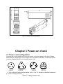
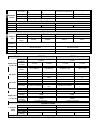
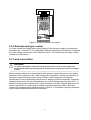
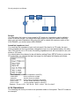
1
USER’S GUIDE
Programmable DC Electronic Load
Models IT8700 series
© Copyright 2011 All Rights Reserved
Ver1.4/Mar, 2011/ IT8700-401
1
WARRANTY INFORMATION ....................................................................................................................... 4
CERTIFICATION ........................................................................................................................................... 4
WARRANTY.................................................................................................................................................. 4
LIMITATION OF WARRANTY ...................................................................................................................... 4
ASSISTANCE................................................................................................................................................ 4
SAFETY SUMMARY ..................................................................................................................................... 4
ENVIRONMENTAL CONDITIONS................................................................................................................ 4
BEFORE APPLYING POWER...................................................................................................................... 5
SAFETY SYMBOLS...................................................................................................................................... 5
CHAPTER 1 PRODUCTS INTRODUCTION ................................................................................................ 7
1.1 INTRODUCTION ...................................................................................................................................... 7
1.2 DESCRIPTION ........................................................................................................................................ 7
1.3 FRONT PANEL DESCRIPTION ................................................................................................................... 8
1.4 REAR PANEL DESCRIPTION ..................................................................................................................... 8
CHAPTER 2 INSPECTION AND INSTALLATION .................................................................................. 10
2.1 INSPECTION ......................................................................................................................................... 10
2.2 CLEAN ................................................................................................................................................ 10
2.3 MODULE INSTALLATION ....................................................................................................................... 10
2.3.1 Channel number ........................................................................................................................ 11
2.4 MAINFRAME INSTALLATION ................................................................................................................... 12
2.4.1 Installation ................................................................................................................................ 12
CHAPTER 3 POWER-ON CHECK ............................................................................................................. 14
3.1 POWER CORD CONFIGURATION ............................................................................................................. 14
3.2 INPUT VOLTAGE SELECTION .................................................................................................................. 15
3.3 TURN-ON CHECKOUT............................................................................................................................ 15
3.4 IF THE ELECTRONIC LOAD DOES NOT TURN ON ....................................................................................... 16
CHAPTER4 TECHNICAL SPECIFICATION .............................................................................................. 17
4.1 M AIN TECHNICAL PARAMETERS ............................................................................................................ 17
4.2 SUPPLEMENTARY CHARACTERISTICS .................................................................................................... 22
CHAPTER5 PANEL FUNCTION INTRODUCTION.................................................................................... 23
INTRODUCTION .......................................................................................................................................... 23
5.1 MAINFRAME OPERATION ....................................................................................................................... 23
5.1.1 Mainframe keyboard functions introduction ............................................................................... 23
5.1.2 Menu list..................................................................................................................................... 25
5.1.3 Channel option........................................................................................................................... 32
5.1.4 Save and recall .......................................................................................................................... 32
5.1.5 Configuration menu introduction................................................................................................ 32
5.1.6 Module keyboard lock ................................................................................................................ 33
5.2 MODULE OPERATION ............................................................................................................................ 33
5.2.1 Single channel module panel..................................................................................................... 33
5.2.2 Dual channel module panel ....................................................................................................... 34
5.3 VFD INDICATOR FUNCTION DESCRIPTION .............................................................................................. 35
5.4 8-PIN CONTROL CONNECTOR ................................................................................................................ 35
5.4.1 External trigger connections ...................................................................................................... 36
5.4.2 External ON/OFF control connection......................................................................................... 37
5.5 EXTENDED FRAME CONNECTIONS ......................................................................................................... 37
5.6 CONTROLLING LINK .............................................................................................................................. 38
5.6.1 Voltage failure indication............................................................................................................ 39
5.6.2 Current monitoring ..................................................................................................................... 39
5.6.3 Digital I/O ................................................................................................................................... 39
5.6.4 Remote measurement connection............................................................................................. 39
5.6.5 External analogue control .......................................................................................................... 40
5.7 LOAD CONNECTION .............................................................................................................................. 40
5.8 PARALLEL CONNECTIONS ..................................................................................................................... 41
CHAPTER6 OPERATIONS INTRODUTION .............................................................................................. 42
6.1 LOCAL/REMOTE OPERATION.................................................................................................................. 42
6.2 PC CONTROL CONNECTION .................................................................................................................. 42
6.3 OPERATING MODES.............................................................................................................................. 43
6.3.1 Constant current (CC) mode...................................................................................................... 43
2
6.3.2 Constant resistance (CR) mode ................................................................................................ 44
6.3.3 Constant voltage (CV) mode ..................................................................................................... 45
6.3.4 Constant power(CW) mode..................................................................................................... 46
6.3.5 Constant impedance(CZ) mode.............................................................................................. 46
6.3.6 Operations ................................................................................................................................. 47
6.4 TRANSIENT OPERATION ........................................................................................................................ 48
6.4.1 Continuous ................................................................................................................................. 48
6.4.2 Pulsed ........................................................................................................................................ 49
6.4.3 Toggled ...................................................................................................................................... 49
6.4.4 A/B transient operations ............................................................................................................ 50
6.5 LIST OPERATION .................................................................................................................................. 51
6.6 TRIGGERED OPERATION ....................................................................................................................... 53
6.6.1 Trigger function .......................................................................................................................... 53
6.6.2 Trigger source............................................................................................................................ 53
6.7 SHORT OPERATION .............................................................................................................................. 54
6.8 INPUT ON/OFF OPERATION .................................................................................................................... 54
6.9 SYNCHRONOUS LOAD ........................................................................................................................... 54
6.10 VON OPERATION ................................................................................................................................ 54
6.11 METER(IT8711/IT8712) .................................................................................................................... 56
6.11.1 Metering operation ................................................................................................................... 56
6.11.2 Metering function front panel operation ................................................................................... 57
6.12 PROTECTION FUNCTIONS.................................................................................................................... 58
6.12.1 Over voltage protection (OVP)................................................................................................. 59
6.12.2 Over current protection (OCP) ................................................................................................. 59
6.12.3 Over power protection (OPP) .................................................................................................. 59
6.12.4 Over temperature protection (OTP) ......................................................................................... 60
6.12.5 Reverse voltage protection (LRV/RRV) ................................................................................... 60
6.13 SAVE AND RECALL OPERATION............................................................................................................ 60
6.14 AUTOMATIC TEST ............................................................................................................................... 60
6.15 CR-LED FUNCTION ........................................................................................................................... 63
CHAPTER7 REMOTE OPERATION .......................................................................................................... 65
3
Warranty Information
Certification
We certify that this product meet its published specifications at time of shipment from the
factory.
Warranty
This hardware product is warranted against defects in material and workmanship for a
period of ONE year from date of delivery. IT8700 series electronic load for use with a
hardware product and when properly installed on that hardware product, are warranted
not to fail to execute their programming instructions due to defects in material and
workmanship for a period of 90 days from date of delivery. During the warranty period our
company will either repair or replace products which prove to be defective. Our company
does not warranty that the operation for the software firmware or hardware shall be
uninterrupted or error free.
For warranty service, with the exception of warranty options, this product must be
returned to a service facility designated by our company. Customer shall prepay shipping
charges by (and shall pay all duty and taxes) for products returned to our place for
warranty service. Our company shall pay for return of products to Customer.
Limitation of Warranty
The foregoing warranty shall not apply to defects resulting from improper or inadequate
maintenance by the Customer, Customer-supplied software or interfacing, unauthorized
modification or misuse, operation outside of the environmental specifications for the
product, or improper site preparation and maintenance.
Assistance
The above statements apply only to the standard product warranty. Warranty options
product maintenance agreements and customer assistance agreements are also
available.
Safety Summary
The following general safety precautions must be observed during all phases of operation
of this instrument. Failure to comply with these precautions or with specific warnings
elsewhere in this manual violates safety standards of design, manufacture, and intended
use of the instrument .We assumes no liability for the customer’s failure to comply with
these requirements.
Environmental Conditions
This instrument is intended for indoor use. Pollution degree 2 environments. It is
designed to operate at a maximum relative humidity of 95% and at altitudes of up to 2000
meters. Refer to the specifications tables for the ac mains voltage requirements and
ambient operating temperature range.
4
Before Applying Power
Verify that all safety precautions are taken. Note the instrument's external markings
described under "Safety Symbols".
Ground the Instrument
This product is a Safety Class 1 instrument (provided with a protective earth terminal). To
minimize shock hazard, the instrument chassis and cover must be connected to an
electrical ground. The instrument must be connected to the ac power mains through a
grounded power cable, with the ground wire firmly connected to an electrical ground
(safety ground) at the power outlet. Note: Any interruption of the protective (grounding)
conductor or disconnection of the protective earth terminal will cause a potential shock
hazard that could result in personal injury.
DO NOT OPERATE IN AN EXPLOSIVE ATMOSPHERE
Do not operate the instrument in the presence of fumes or flammable gases.
KEEP AWAY FROM LIVE CIRCUITS
Operating personnel must not remove instrument covers except as instructed in this
Guide for installing or removing electronic load modules. Component replacement and
internal adjustments must be made only by qualified service personnel. Do not replace
components with power cable connected. Under certain conditions dangerous voltages
may exist even with the power cable removed. To avoid injuries always disconnect power,
discharge circuits, and remove external voltage sources before touching components.
DO NOT SERVICE OR ADJUST ALONE
Do not try to do some internal service or adjustment unless another person capable of
rendering first aid resuscitation is present.
Safety Symbols
Direct current
Alternating current
Both direct and alternating current
Protective earth (ground) terminal
Caution (refer to accompanying documents)
WARNING
The WARNING sign denotes a hazard. It calls attention to a procedure, practice, or the
like, which, if not correctly performed or adhered to, could result in personal injury. Do not
proceed beyond a WARNING sign until the indicated conditions are fully understood and
met.
CAUTION
The CAUTION sign denotes a hazard. It calls attention to an operating procedure, or the
like, which, if not correctly performed or adhered to, could result in damage to or
5
destruction of part or all of the product. Do not proceed beyond a CAUTION sign until the
indicated conditions are fully understood and met.
Introduction
IT8700 DC electronic loads are multichannel programmable electronic loads. With
RS232 /GPIB /USB/ EtherNet communication interfaces, the series DC electronic loads
can provide multi solution according to the requirements of your design and test. IT8700
DC electronic loads provide you with the flexibility to test a wide range of applications
from multi-output AC/DC power supply, DC/DC converter, charger to power electronic
components. It is configured by plugging the user selectable modules into the
mainframe, and operated using the keypad and rotary knob on the front panel or the
remote controlled instructions via Ether Net, USB, RS-232C or GPIB interface. The high
resolution voltage(0.1mV), current(0.01mA) measurement system(Up to 1k Hz
sampling ) provides both accuracy and convenience. User can simulate a wide range of
dynamic loading (Up to 25K Hz) applications. The loading waveform is user
programmable in slew rates, load levels, duration and conducting voltage.
Removable channels: increase system flexibility
Dynamic Power distribution function for dual channels, save your cost
Dual-channel module can display every channel information simultaneously with no
need to switch
Measure peak current in short-circuit
Transient mode: Up to 25KHZ; List mode : 100KHZ
Measurement resolution: 0.1mV,0.01mA
Measurement speed: up to 1KHZ
A unit with single mainframe can take up to 8 channels, with extended mainframe up
to 16 channels
Adjustable slew rate
Support several electronic loads working at the same time
Auto-test function
Output resolution up to 16 bits ,voltmeter and ammeter reach 5 1/2 digits
Constant current(CC),constant voltage(CV),constant resistance(CR) mode
Highlight VFD display for both mainframe and load modules
Support USBTMC/SCPI communication protocol
Output terminals on the rear panel make wiring easy and keep front panel clean
Simulate the transient response and export measured values in time
Built-in waveform generator and LIST mode
Ethernet ,GPIB ,USB ,RS232 interfaces
6
Chapter 1 Products Introduction
1.1 Introduction
This user’s manual introduces the specifications, installation, operation and
programming of IT8700 series DC electronic loads. There’re two parts in IT8700 DC
electronic loads, mainframe/ extended frame and modules. The frames mentioned are
IT8702 mainframe and IT8703 extended frame. Modules refered to are IT8711、IT8712、
IT8731、IT8732、IT8732B、IT8733、IT8733B、IT8722 and so on. The range of every
module’s specific voltage, current and power will be introduced in the specifications in
detail.
1.2 Description
The dimension of IT8702 is same as that of IT8703.The difference is that IT8702 is
four modules control unit while IT8703 is a extended unit. There are up to 8 channels in
IT8702 mainframe. After extended with IT8703 mainframe,it can be up to 16 channels. All
panel operation and programming are also carried on the IT8702 main panel.
One module could have one or two channels,each module will have its own channel
number according to the slot position.In the case of IT8702 mainframe,if each slot has
one channel,then the channel number from right to left should be:1th channel,3th
channel,5th channel….For module with dual channels,the channel number should be:1th
and 2th channels,3th and 4th channels,5th and 6th channels….IT8703 extended
mainframe can be understanded in the same way.
Modules IT8711、IT8712 have the same menu functions.IT8731、IT8732、IT8732B、
IT8733、IT8733B、IT8732 are with the same menu functions.The difference is in the range
of input voltage,current and power.Following are the similarities and differences of menu
functions between IT8711’s and IT8731’s.
Module IT8711、
、IT8712:
:
Working functions:constant current mode(CC),constant resistance(CR),constant
voltage(CV)
Enable you to set the rising slope and falling slope of current,voltage or resistance in
dynamic mode,dynamic functions has three modes:CC,CV or CR
CV mode has no high and low range selections
Dynamic mode:up to 25KHZ,list mode:up to 100KHZ
Voltage measuring resolution:0.1mV,0.01mA,measuring speed could reach 1KHZ
With remote sense function
Short-circuit function
Storage capacity:101 sets
List mode:enable you to edit a list file in CC,CV or CR mode.step range: 2-255,each
step time:0.000001~16383s.You can save six list files.
Autotest function:enable you to edit 10 files at most,each file will have 10 steps
Module IT8731,IT8732,IT8732B,IT8733,IT8733B,IT8722
Working functions:constant current(CC),constant resistance(CR),constant
voltage(CV),constant power(CW),constant impedance(CZ)
Enable you to set the rising slope and falling slope of current in dynamic
mode,dynamic functions has one mode:CC
Dynamic mode:up to 25KHZ,list mode:up to 100KHZ
7
Voltage measuring resolution:0.1mV,0.01mA,measuring speed could reach 50KHZ
With remote sense function
Short-circuit function
Storage capacity:101 sets
List mode:enable you to edit a list file in CC mode.number of list steps: 2-84,each
step time:0.000020~3600s.You can save seven list files.
CR-LED function
1.3 Front panel description
There’re two parts in front panel,which are main panel and module panel. Please read
figure 1-1 for details. Main panel and module panel keys’ function will be introduced
below.
Figure 1-1 IT8700 front panel
1
2
3
4
5
5
VFD display
Module keyboard: <A/B>,<Short>,<Tran>,<Mode>,<On/Off> and direction keys.
Adjustment knob,change parameters
Mainframe function keyboard: control each channel’s operating status.
specific buttons: <Chan>, <Save>, <Reall>, <Setup>, <On/Off>, <Trig>, <Start>,
<Pause>, <Enter>, <Shift>, <▲>, <▼>.
Mainframe compound button((numeric keys):1.set parameters 2.assembled menu
function.detailed buttons:<1>,<2>,<3>,<4>,<5> plus function keys to enter the
system menu, <6> plus function keys to enter the config menu,<7> plus function
keys to enter program menu,<8> plus function keys to select local operation, <9>
plus function keys to select lock function,<0>,<.>.
Power switch ON/OFF
1.4 Rear panel description
8
The part introduces the location of terminals and interfaces on the rear panel. see figure
1-2 for more details.
13
11
12
11 12
14
10
10
9
8
7
6
5
4
3
2
1
Figure 1-2 IT8700 rear panel
1
Current monitoring terminal
2
Remote sense and external input control terminal
3
Digital I/O and VF output signal teminal
4
Power input socket
5
Extended module interface
6
USB communication cable interface
7
Line voltage slection switch(110V/220V)
8
Trigger input /output and ON/OFF input/output interface
9
Network interface
10
9-pin COM port interface connector(RS232 communication cable interface)
11
9-pin COM serial port connector(extended keyboard interface )
12
GPIB interface
13
Positive input terminal of module
14
Negative terminal of module
9
Chapter 2 Inspection and installation
This chapter will introduce the acceptance items after you receive the new unit.
2.1 Inspection
Please confirm whether the outer box is good,then broke open the packing cases to
see if there is any damage caused in the transportation.Simultaneously,make sure the
following standard accessories are not missing.If any is missed,please contact with the
most nearest available distributors.
Take one unit as a reference:
● One power line
● One user’s manual
● One delivery inspection report
2.2 Clean
If you want to clean the outer cover of the unit,please wipe with a dry or moistish cloth.Do
not clean the unit’s internal part randomly.
Caution:Make sure you have cut off the electricity supply before you start the
cleaning.
2.3 Module installation
Cautions:
Franklinism will damage the module.Please install the module according to standard
electostatic prevention operation style.Avoide touching the circuit board and connectors.
Installation steps:
● Turn off the power switch and disconnect the 110V/220V power cord.
● Take off any packing materials around the mainframe.
● Push the module into the slot(as shown in fingure 2-1)
● Fix the module with a screwdriver,the position of the screw is in the upside and
backside of the machine frame.
● Install other modules one by one
10
模 组
Module
主机
Mainframe
e
Figure 2-1 module installation
2.3.1 Channel number
To IT7800, the channel number for all modules is determined by the location of the
modules in relation to right side of the mainframe. To IT8702 mainframe,the total channel
number is 8. the 1st & 2nd channel are always next to the mainframe while 7,8 channels
are always next to the left side. Load channel number is fixed even if the location isn’t
occupied. Double-channel module has two channels, e.g IT8722. If it’s single channel
module,the channel number is automatically assigned the first number of the slot. The
following picture show the channel number default order.
Channel number sequentially are: 8,7,6,5,4,3,2,1
Fig 2-2A channel number distribution
For example:If IT8702 mainframe contains two single channel modules IT8711and two
double channels modules IT8722. Channel number is automatically assigned to every
channel at the sequence from right to left:1,3,5,6,7,8. Now channel number 2,4 aren’t
occupied.You can base on your test request to configure the modules(single
module:IT8711,IT8712,IT8731,IT8732,IT8732B,IT8733,IT8733B;double module:IT8722).
11
Channel 7
Channel 5 Channel 3
Channel 1
Fig 2-2B channel number order while installing 4
图 2-2 单通道编号的例子
single-channel
unit
2.4 Mainframe installation
The operating temperature of IT8700 series electronic load is 0 to 40℃. A fan cools the
electronic load by drawing air through the top and sides and exhausting it out the back.
The electronic load must be installed in a location that allows sufficient space at the sides
and back of the unit for adequate air circulation. Minimum clearances for bench operation
are 3cm on the top. If there are radiator fan in your cabinet,please avoid installing the
load near the fan for cabinet fan limiting air circulation of load. If you are installing
equipment on top of your electronic load in the cabint,use a filler panel above the unit to
ensure adequate for air circulation.
IT8700 series can be mounted in a standard 19-inch rack panel r cabinet. When it’s
mounted,there’s no need to remove the bottom studs. You can achieve it use
IT-E153(optional).
CAUTION:
:
Do not block the fan exhaust at the rear of the Load
When the load uses on the desk ,make sure there enough space on the bottom of the
equipment for air circulation.
2.4.1 Installation
Mainframe dimension:445 mmW x 183mm H x 549mm D
The outline diagram in fig 2-4 gives the dimensions of the electronic loads:
12
IT8702 mainframe size
IT8702 installation figure
IT8703 Extended mainframe installation figure(
(dimension is same as IT8702)
)
unit:milimeter(mm)
figure2-3A IT8702 and IT8703 outline diagram
Figure 2-4 IT8702 and IT8703 dimensioned drawing
Module dimension:82 mmW x 183mm H x 549mm D(IT8711/IT8712/IT8722)
The outline diagram in figure 2-5 gives the dimensions of module.
13
Fig 2-5 module outline diagram
Chapter 3 Power-on check
3.1 Power cord configuration
Connect the correct power cord to the connector on the rear panel of the load. Please
select the line voltage type of your region from the power cord below. If the wrong power
cord was shipped,contact your nearest vendor of us.
E
E
E
N
L
L
E
N
N
L
L
CHINA
USA,
,Canada
Europe
N
England
IT-E171
IT-E172
IT-E173
IT-E174
(L:Live or Active Conductor(also called “live” or “hot”; N:Neutral or identified conductor;
E:Earth or Safety Ground)
Figure 3-1 types of power cord
14
Item
Power cord
Part Number
IT-E171
IT-E172
IT-E173
IT-E174
Users’manual
Description
you can choose difference power line
according to regions
including installation ,operation,self-test
information
programming software,technical
information and communication protocol
test report before ex-factory
Software CD
Test report
3.2 Input voltage selection
The load can work under 110/220V±10%AC input,as the label shown on the rear(refer to
figure 3-2). If the default value on the label doesn’t match your region’s, please switch
the black key to choose input line voltage,and then insert power cord. Choose the right
linear voltage as following.
:
CAUTION:
Thre’s no need to change fuse when linear voltage changes. The fuse can protect
the electronic load at any setting voltage specified.
220V
110V
Power switch
Figure 3-2 power switching keys
3.3 Turn-on checkout
When you turn on the electronic load, the front-panel display will light up briefly while the
electronic load perform its power-on self-test. The following table show the procedure of
the self-test.
Procedure
Mainframe
VFD Describe
display
BOIS Ver 1.00
VFD display software version
When
powered on
about 1S later SYSTEM
TEST
SELF system self-check
15
about 1S later CH1/2/3/4/5/6/7/8
detect all modules installed
SCAN…
about 1S later
□7□5□3□1
e.g.:
:CH01 CV OFF
Vdc=0.0000V
Adc=0.0000A
Wdc= 0.00W
Display information of channel 1 or the leftmost
channel. Use up and down key to select other
channels.
WARNING:
:The electronic load is shipped from factory with a power cord
that has a plug appropriate for your location. Your electronic load is
equipped with 3-wire grounding type power cord; the third conductor being
ground. The electronic load is grounded only when the power-line cord is
plugged into an appropriate receptacle. Do not operate your power supply
without adequate cabinet ground connection.
3.4 If the electronic load does not turn on
Use the following steps to help solve problems you might encounter when turning on the
instrument:
1) Verify that there is AC power to the power supply.
First, verify that the power cord is firmly plugged into the power receptacle on the rear panel of the
electronic load. You should also make sure that power source you plugged the electronic load into is
energized. Then, verify that the electronic load is turned on.
2)
Verify the power-line voltage setting.
The line voltage is set to the proper value for your country(110VAC or 220VAC) when the
electronic load is shipped from facory. Change the line voltage setting if it’s not correct.
3)
Verify that the correct power-line fuse is installed.
If fuse is blowout, please replace it according to the following specification.
Product
IT8702
IT8703
Fuse specification (110VAC)
T5A 250V
T5A 250V
Fuse specification (220VAC)
T3.15A 250V
T3.15A 250V
4) The method to replace fuse
Use a flat-bladed screwdriver to open the small plastic cover under the AC input
connector on the rear panel of the load ,then you can see the fuse. Please use the
matching fuse.(figure2-6 shows the fuse location)
16
Fuse
Fig 3-3 fuse location
Chapter4 Technical specification
4.1 Main technical parameters
Model
Rated
value
( 0~
~40
℃)
CV mode
CC mode
CR mode
IT8711
Input voltage
Input current
Input power
0~4A
Min operation
voltage
0.14V at 4A
range
Resolution
accuracy
range
Resolution
accuracy
range
Resolution
accuracy
IT8712
0~80V
0~80V
0~40A
0~6A
200 W
0~60A
300W
1V at 40A
0.14V at 6A
0~80V
1mV
1.4V at 60A
0~80V
1mV
±(0.05%+0.02%FS) ±(0.05%+0.025%FS)
±(0.05%+0.02%FS)
±(0.05%+0.025%FS)
0~4A
0.1mA
0~40A
1mA
0~6A
0.1mA
0~60A
±(0.05%+0.05%FS)
±(0.05%+0.05%FS)
±(0.05%+0.05%FS)
±(0.05%+0.05%FS)
0.05Ω~18Ω
16bit
0.01%+0.08S
18Ω~7.5KΩ
16bit
0.01%+0.0008S
0.05Ω~18Ω
16bit
0.01%+0.08S
1mA
18Ω~7.5KΩ
16bit
0.01%+0.0008S
Dynamic mode
CC mode
10uS~16383S/Res:1uS
T1&T2
Dynamic
accuracy
5uS+100ppm
mode
Rising/falling
0.0001~0.25A/uS
0.001~2.5A/uS
slope
CC mode
10uS~16383S/Res:1uS
5uS+100ppm
0.0001~0.35A/uS
0.001~2.5A/uS
0~18V
0.1 mV
0~80V
1 mV
Measuring range
Readback
voltage
range
Resolution
0~18V
0.1 mV
0~80V
1 mV
17
±(0.025%+0.025% ±(0.025%+0.025%
FS)
FS)
range
0~4A
0~40A
Resolution
0.01mA
0.1mA
accuracy
±(0.05%+0.05%FS)
accuracy
Readback
current
±(0.025%+0.025%FS
)
0~6A
0~60A
0.01mA
0.1mA
±(0.05%+0.05%FS)
±(0.025%+0.025%FS)
Protection range
≒200W
OPP
OCP
OVP
OTP
≒300W
≒4.4A
≒44A
≒6.6A
≒66A
≒82V
≒85℃
≒82V
≒85℃
Specification
current(CC)
Short-cir voltage(CV)
cuit
resistance
(CR)
Input
impedance
dimensio
n
weight
safety
≒4.4/4A
0V
≒44/40A
0V
≒6.6/6A
0V
≒60.6/60A
0V
35mΩ
35mΩ
35mΩ
35mΩ
120KΩ
120KΩ
82*183*573mm
82*183*573mm
5KG
CE
5KG
CE
Model
Input
voltage
Input
Rated value
current
( 0~
~40 ℃)
Input power
CV mode
0~3A
range
Resolution
0~18V
1mV
accuracy
range
Resolution
accuracy
Input
voltage
Rated value
Input
( 0~
~40 ℃)
current
Input power
CR mode
0~80V
0~20A
0~12A
300 W
0.7V at 3A
range
Resolution
IT8733
0~500V
Min operation
voltage
accuracy
CC mode
IT8732B
0~120A
600W
4.5V at 20A
0~500V
10mV
±(0.05%+0.025%
±(0.05%+0.02%FS)
FS)
0~3A
0~20A
0.01mA
0.1mA
±(0.05%+0.05%F
±(0.05%+0.05%FS)
S)
0.25Ω~10Ω
10Ω~7.5KΩ
16bit
0.01%+0.08S
0.01%+0.0008S
0.18V at 12A
1.8V at 120A
0~18V
1mV
0~80V
10mV
±(0.05%+0.025%F
S)
0~120A
1mA
±(0.05%+0.02%FS)
0~12A
0.1mA
±(0.05%+0.1%FS)
0.2Ω~10Ω
±(0.1%+0.1%FS)
10Ω~7.5KΩ
16bit
0.01%+0.08S
0.01%+0.0008S
300W
600W
10mW
10mW
±(0.2%+0.2%FS)
±(0.2%+0.2%FS)
Dynamic mode
T1&T2
Dynamic
accuracy
mode
Rising/fallin
g slope
CC mode
20uS~3600S /Res:1u S
5uS+100ppm
0.0001~0.5A/uS
0.001~1A/uS
Measuring range
18
CC mode
20uS~3600S /Res:1u S
5uS+100ppm
0.0001~0.25A/uS
0.001~2.5A/uS
0~18V
0~500V
0.1 mV
1 mV
±(0.025%+0.025%F ±(0.025%+0.025
accuracy
S)
%FS)
range
0~3A
0~20A
Readback
Resolution
0.01mA
0.1mA
current
accuracy
±(0.05%+0.05%FS)
range
300W
Readback
Resolution
10mW
power
accuracy
±(0.2%+0.2%FS)
Readback
voltage
range
Resolution
0~18V
0.1 mV
±(0.025%+0.025%FS)
0~80V
1 mV
±(0.025%+0.025%F
S)
0~120A
1mA
±(0.1%+0.1%FS)
0~12A
0.1mA
±(0.05%+0.1%FS)
600W
10mW
±(0.2%+0.2%FS)
Protection range
≒300W
OPP
OCP
OVP
OTP
≒600W
≒3.3A
≒22A
≒13.2A
≒132A
≒82V
≒85℃
≒82V
≒85℃
Specification
current(CC)
voltage
Short-circ
(CV)
uit
resistance
(CR)
Input
impedance
dimensio
n
weight
safety
≒3.3/3A
≒22/20A
≒13.2/12A
≒132/120A
0V
0V
0V
0V
≒200mΩ
≒200mΩ
≒15mΩ
≒15mΩ
≒1MΩ
≒300KΩ
82*183*573mm
82*183*573mm
5KG
CE
5KG
CE
Model
Rated value
( 0~
~40 ℃)
Input
voltage
Input
current
Input power
Min
operation
voltage
CV mode
range
Resolution
accuracy
CC mode
range
Resolution
accuracy
CR mode
Rated value
( 0~
~40 ℃)
range
Resolution
accuracy
range
Resolution
accuracy
IT8731
IT8732
0~80V
0~80V
0~4A
0~40A
0~6A
200 W
0.10V at 4A
0~60A
400W
1V at 40A
0.15V at 6A
1.5V at 60A
0~18V
0~80V
0~18V
0~80V
1mV
10mV
1mV
10mV
±(0.05%+0.02%FS ±(0.05%+0.025%F
±(0.05%+0.02%FS) ±(0.05%+0.025%FS)
)
S)
1mA~60A
0~4A
0~40A
0~6A
1mA
0.1mA
1mA
0.1mA
±(0.05%+0.05%FS
±(0.05%+0.05%FS)
±(0.05%+0.05%FS) ±(0.05%+0.05%FS)
)
0.05Ω~10Ω
10Ω~7.5KΩ
0.05Ω~10Ω
10Ω~7.5KΩ
16bit
16bit
16bit
16bit
0.01%+0.08S
0.01%+0.0008S
0.01%+0.08S
0.01%+0.0008S
200W
400W
10mW
10mW
±(0.2%+0.2%FS)
±(0.2%+0.2%FS)
Dynamic mode
Dynamic
CC mode
CC mode
19
mode
20uS~3600S /Res:1u S
T1&T2
accuracy
5uS+100ppm
Rising/fallin
0.0001~0.25A/uS
0.001~2.5A/uS
g slope
20uS~3600S /Res:1u S
5uS+100ppm
0.0001~2.5A/uS
0.001~2.5A/uS
Measuring range
Readback
voltage
Readback
current
Readback
power
range
Resolution
accuracy
range
Resolution
accuracy
range
Resolution
accuracy
0~18V
0~80V
0~18V
0~80V
0.1 mV
1 mV
0.1 mV
1 mV
±(0.025%+0.025% ±(0.025%+0.025%F ±(0.025%+0.025%FS ±(0.025%+0.025%FS
FS)
S)
)
)
0~4A
0~40A
0~6A
0~60A
0.01mA
0.1mA
0.1mA
1mA
±(0.05%+0.05%FS)
±(0.05%+0.05%FS)
200W
400W
10mW
10mW
±(0.2%+0.2%FS)
±(0.2%+0.2%FS)
Protection range
≒200W
OPP
OCP
OVP
OTP
≒400W
≒4.4A
≒44A
≒6.6A
≒82V
≒85℃
≒66A
≒82V
≒85℃
Specification
current
(CC)
voltage
Short-circuit
(CV)
resistance
(CR)
≒4.4/4A
≒44/40A
≒6.6/6A
≒66/60A
0V
0V
0V
0V
≒25mΩ
≒25mΩ
≒25mΩ
≒25mΩ
300KΩ
82*183*573
5KG
CE
Input impedance
dimension
weight
safety
300KΩ
82*183*573
5KG
CE
Model
Input
voltage
Input
Rated value
current
( 0~
~40 ℃) Input power
IT8733B
0~500V
0~3A
0~30A
500 W
Min
operation
voltage
0.54V/3A
5.4V/30A
range
Resolution
accuracy
range
Resolution
0~18V
1mV
±(0.05%+0.02%FS)
0~3A
1mA
0~500V
10mV
±(0.05%+0.025%FS)
0~30A
10mA
accuracy
range
CR mode
Resolution
accuracy
Rated value
range
Resolution
±(0.05%+0.05%FS)
0.2Ω~10Ω
±(0.05%+0.05%FS)
10Ω~7.5KΩ
CV mode
CC mode
16bit
0.01%+0.08S
0.01%+0.0008S
500W
10mW
20
( 0~
~40 ℃)
accuracy
±(0.2%+0.2%FS)
Dynamic mode
Dynamic
mode
CC mode
20uS~3600S/Res:1uS
5uS+100ppm
T1&T2
accuracy
Rising/fallin
g slope
0.0001~0.1A/uS
0.001~1A/uS
Measuring range
range
Resolution
accuracy
range
Readback
Resolution
current
accuracy
range
Readback
Resolution
power
accuracy
Readback
voltage
0~18V
0.1 mV
±(0.025%+0.025%FS)
0~3A
0.01mA
0~500V
1 mV
±(0.025%+0.025%FS)
0~30A
0.1mA
±(0.05%+0.05%FS)
500W
10mW
±(0.2%+0.2%FS)
Protection range
≒500W
OPP
OCP
OVP
OTP
≒3.3A
≒33A
≒510V
≒85℃
Specification
current
(CC)
Short-circu voltage
it
(CV)
resistance
(CR)
≒3.3/3A
≒33/30A
0V
0V
150mΩ
150mΩ
Input
impedance
1MΩ
dimension
weight
safety
82*183*573mm
5KG
CE
Model
Input
voltage
Input
Rated value
current
( 0~
~40 ℃) Input power
Min
operation
voltage
CV mode
CC mode
IT8722
Channel 1
Channel 2
0~80V
0~80V
0~3A
0~20A
0~3A
250 W
0.15V at 3A
0~20A
250W
1V at 20A
range
Resolution
0.15V at 3A
1V at 20A
0~18V
0~80V
0~18V
0~80V
1mV
10mV
1mV
10mV
±(0.05%+0.02%F
±(0.05%+0.025%FS
accuracy
±(0.05%+0.025%FS) ±(0.05%+0.02%FS)
S)
)
0~20A
range
0~3A
0~20A
0~3A
1mA
Resolution
0.1mA
1mA
0.1mA
21
±(0.05%+0.05%F
±(0.05%+0.05%FS)
S)
range
0.05Ω~10Ω
10Ω~7.5KΩ
CR mode
Resolution
16bit
accuracy
0.01%+0.08S
0.01%+0.0008S
Input
250W
voltage
Rated value
Input
( 0~
~40 ℃)
10mW
current
Input power
±(0.2%+0.2%FS)
accuracy
±(0.05%+0.05%FS)
±(0.05%+0.05%FS)
0.05Ω~10Ω
10Ω~7.5KΩ
16bit
0.01%+0.08S
0.01%+0.0008S
250W
10mW
±(0.2%+0.2%FS)
Dynamic mode
Dynamic
mode
CC mode
20uS~3600S/Res:1uS
5uS+100ppm
T1&T2
accuracy
Rising/fallin
0.0001~0.2A/uS
g slope
CC mode
20uS~3600S/Res:1uS
5uS+100ppm
0.001~2A/uS
0.0001~0.2A/uS
0.001~2A/uS
Measuring range
0~18V
0~80V
0~18V
0~80V
0.1 mV
1 mV
0.1 mV
1 mV
±(0.025%+0.025 ±(0.025%+0.025%FS ±(0.025%+0.025%F ±(0.025%+0.025%F
accuracy
%FS)
)
S)
S)
range
0~3A
0~20A
0~3A
0~20A
Readback
Resolution
0.01mA
0.1mA
0.01mA
0.1mA
current
accuracy
±(0.05%+0.05%FS)
±(0.05%+0.05%FS)
range
100W
250W
Readback
Resolution
10mV
10mV
power
accuracy
±(0.2%+0.2%FS)
±(0.2%+0.2%FS)
Readback
voltage
range
Resolution
Protection range
OPP
OCP
OVP
OTP
≒250W
≒3.3A
≒250W
≒22A
≒3.3A
≒82V
≒85℃
≒22A
≒82V
≒85℃
Specification
current
(CC)
Short-circu voltage
it
(CV)
resistance
(CR)
≒3.3/3A
≒33/30A
≒3.3/3A
≒33/30A
0V
0V
0V
0V
≒50mΩ
≒50mΩ
≒50mΩ
≒50mΩ
Input
impedance
dimension
weight
300KΩ
82*183*573mm
CE
4.2 Supplementary characteristics
Storage capacity:
:101 sets
Suggested calibration frequency:
:one time each year
AC input grade:
22
Option Opt.1: 220V ±10% 50Hz/60Hz
Option Opt.2: 110V ±10% 50Hz/60Hz
Cooling style
fans
Fans control temperature:
Temperature 35°C
Fans status
50°C
70°C
85°C
The first grade The second grade The third grade OTP
Operation environment temperature:
0 to 40 °C
Storage temperature
-20 to 70 °C
Using conditions:
Designed for indoor use,the maxmum humidity 80%
Chapter5 Panel function introduction
Introduction
This chapter mainly introduces the functions and operations of front panel keys. It mainly
describes the main frame’s front panel keyboard operation, single /dual channel module
keyboard operation and VFD display.
5.1 Mainframe operation
The frontpanel keys is effective only in the local mode. When the load is powered on, it
works in local mode automatically, and then you can select channel number and set
parameters such as voltage, current via the front panel keys. When the load is repowered
on, the mainframe will scan all the installed modules once again, and can recall the
parameters of the last power off.
5.1.1 Mainframe keyboard functions introduction
23
IT8702 Electronic
mainframe
2
Chan
Sav
Recal
Setu
On/Off
Tri
Star
Paus
.
0
Es
Ente
1
2
3
▲
System
Confi
Confi
4
5
Loca
Lock
7
8
3
4
Program
6
▼
9
Shif
1
Fig 3-1 IT8702 mainframe front panel
1
Power switch: turn the electronic load on and off. Connect the load with
110/220V voltage correctly, press the POWER button, all the front panel will light up
briefly while all the channels perform the power-on self-test.
2
VFD display: press the POWER key, the VFD screen lit, and shows the version
number of this instrument’s BOOT software, about 1S later, the system begin to
self-test, after about 1S, check all the installed modules of the load, and display every
channel’s number, voltage and current measurements.
3 Function keys:the following are the detailed description about the functions and
specific operations achievable of all the keys. Switch channel via Chan key:IT 8700
is a muti-load, one main frame controls all modules. Every module has its own
channel number, select the channel to be edited on the main frame panel first, then
start to edit, e.g. if you want to edit the 5th channel, press Chan key first, the VFD will
show all the installed channels, press number key 5 directly to switch to 5 channel,
now the channel can be edited .
Save
key is used to save data:after selecting the channel, edit its parameters, set
work mode, voltage, current, Slope, the dynamic parameters and so on. Press Save
key to save, up to 101 groups of parameters can be saved. All the parameters are
saved in the Non-volatile memory, support power-off saving.
Recall
key is used to recall data: Recall key can be used to fast recall the saved
101goups parameters. All the used parameters are only need to be edit and save for
one time, they will be always saved in the EPROM. You just need to recall them if
necessary. It brings great convenience to the users, and save time.
24
Setup
key is used to enter the specific channel’s menu:press this key, you can
achieve A/B transient mode, CC/CV/CR mode and so on, this menu has been
introduced in detail in the menu list.
On/Off
key is used to control module’s input state on/off: when you enabled the
synchronization function in the menu of a channel, the key can correspondly control
the on/off state of the channel.
Trig
key is used to trigger: when you edit the auto test file or the transient output, you
should select the triggering source, this load have 5 kinds triggering mode, panel
triggering is only one of them. It will be introduced in detail in the front panel
triggering operation chapter.
Start
key is used to start automatic test:after recalling the edited automatic test file,
press Start key to start automatic test.
Pause
key is used to pause:only press Pause key to pause when running a automatic
test, at this time the VFD will display pausing at a step, press Pause key once
again to test the file continuously.
4
Comprehensive key+
Shift
+
4
/
5
/
6
0
~
9
number keys:
0
~
Shift
are number input keys;
key will respectively enter 3 menu, it has been introduced in detail in
the menu list; if the load is in remote sense mode, press
local mode;
9
+
8
Shift
+
7
key can switch to
key can lock module’s panel keyboard and knob, re press
.
Esc
exit key, can be used to exit any working state;
key means
them can unlock it;
▼
▲
a point;
key is used to move up, select the menu;
key is used to move
Shift
Enter
down, select the menu;
key is used to confirm;
key is a Comprehensive
key.
5.1.2 Menu list
Setting menu
key to enter menu setting, view the menu in VFD and use ▲
and
▼
Enter
to scroll through the completely menu list as following. press
key to enter the
▼
▲
selected menu function, use
and
to scroll through the VFD screen, press
Press
Setup
Esc
Enter
key to enter the under submenu, press
back to the previous menu selection
page. Pressing number keys can directly select a channel.
Setup menu list of IT8711/IT8712 module:
SET UP
MODE
Select working mode
CONST CURRENT
Load works in CC mode
CONST VOLTAGE
Load works in CV mode
CONST RESISTANCE
Load works in CR mode
25
RANGE(CC/CR)
Switch the range
HIGH RANGE
LOW RANGE
I / V / R SET
Set the working current/voltage/resistance
∫=2.500A/uS
Set the up slope
∫=2.500A/uS
Set the down slope
TRAN A=0.00A
Setup level A value
Ta=0.0005S
Setup level A width
TRAN B=0.00A
Setup level B value
Tb=0.0005S
Setup level B width
T MODE
Setup the transient mode
CONTINUOUS
Continuous mode
PULSE
Pulse mode
TOGGLE
Toggle mode
Vmax=82.000V
Setup the maximum voltage value
Vmin=0.000V
Setup the minimum voltage value
value
Setup menu list of IT8732B/IT8733/IT8733B/IT8731/IT8732:
SET UP
MODE
Select working mode
CONST CURRENT
Load works in CC mode
CONST VOLTAGE
Load works in CV mode
CONST RESISTANCE
Load works in CR mode
CONST POWER
Load works in CW mode
CONST IMPEDAN
Load works in CZ mode
CC/CV RANGE
Switch the range
HIGH RANGE
LOW RANGE
I / V / R /W SET
Set the working current/voltage/resistance value
Vmax/Amax
Setup the maximum voltage value/maximum current value
Vmin/Amin
Setup the minmum voltage value/minmum current value
∫=2.500A/uS
Set the up slope (only CC mode avaliable)
∫=2.500A/uS
Set the down slope(only CC mode available)
TRAN A=0.00A
Setup level A value
Ta=0.0005S
Setup level A width
TRAN B=0.00A
Setup level B value
Tb=0.0005S
Setup level B width
T MODE
Setup the transient mode
CONTINUOUS
Continuous mode
PULSE
Pulse mode
TOGGLE
Toggle mode
RLC R=7500.0Ω Setup the resistance value
RLC L=0uH
Setup the inductance value
RLC C=10uF
Set the capacitance value
Setup menu list of IT8722 module:
SET UP
MODE
Select working mode
26
CONST CURRENT
Load works in CC mode
CONST VOLTAGE
Load works in CV mode
CONST RESISTANCE
Load works in CR mode
CONST POWER
Load works in CW mode
CONST IMPEDAN
Load works in CZ mode
CC/CV RANGE
Switch the range
HIGH RANGE
LOW RANGE
I / V / R /W SET
Set the working current/voltage/resistance value
Vmax/Amax
Setup the maximum voltage value/maximum current value
Vmin/Amin
Setup the minmum voltage value/minmum current value
∫=2.500A/uS
Set the up slope (only CC mode available)
∫=2.500A/uS
Set the down slope(only CC mode available)
TRAN A=0.00A
Setup level A value
Ta=0.0005S
Setup level A width
TRAN B=0.00A
Setup level B value
Tb=0.0005S
Setup level B width
T MODE
Setup the transient mode
CONTINUOUS
Continuous mode
PULSE
Pulse mode
TOGGLE
Toggle mode
RLC R=7500.0Ω Setup the resistance value
RLC L=0uH
Setup the inductance value
RLC C=10uF
Set the capacitance value
Configuration menu
5
Press Shift + key to enter the channel configuration menu
Configure menu list of IT8711/IT8712 module:
MENU
Setup Synchronization ON / OFF function
ON〈
〈DEFAULT〉
〉
Turn on synchronization function
OFF
Turn off synchronization function
SYNC ON SET
VON
VON POINT
VON LATCH
EXIT
METER
Set the load’s von point
Von point latch state, ON /OFF
Meter function
Select voltmeter’s range
High voltage range
Low voltage range
Automatic select
Select Ammeter mode
MEASURE ADX
DC current meter
MEASURE AMAX
Maximum current meter
SPEED
Select metering speed
HIGH ACCURARY
High accurary
SLOW〈
〈26HZ〉
〉
Slow speed
VRANGE SEL.
HIGH VRANGE
LOW VRANGE
AUTO
AMODE SELECT
27
MEDIUM〈
〈172HZ〉
〉
Medium speed
FAST〈
〈384HZ〉
〉
Fast speed
FILTER STATE
Filter function
ON
enable the filter function
OFF〈
〈DEFUALT〉
〉
disable the filter function
FILTER MODE
Filter mode setting
AVERAGING
Averaging mode
ADVANCE〈
〈DEF〉
〉
AVERAGE CNT
Average cnt setting(
(2-100)
)
EXIT
Load protecting function
MAX POWER SET
Setup hardware power protecting
ALIMIT STATE
Setup software current protecting state
ON
Put on
OFF〈
〈DEFAULT〉
〉
Put off
ALIMIT POINT
Setup software current protecting value
ALIMIT DELAY
Setup software current protecting delay
PLIMIT POINT
Setup software power protecting value
PLIMIT DELAY
Setup software power protecting delay
ON TIMER STATE
Setup LOAD ON timer state
ON TIMER SET
Setup LOAD ON timer time
PROTECT
EXIT
LIST
Select Mode
Choose fixed operation mode
Choose list operation mode
Recall list operation file
Edit list operation file
CC
LIST
In CC mode ,Edit list testing file
CV
LIST
In CV mode ,Edit list testing file
CR
LIST
In CR mode ,Edit list testing file
EXT. CTR 1 SET External analog control function
ON
Turn on external analog control function
OFF〈
〈DEFAULT〉
〉
Turn off external analog control function
ABOUT
Module production information
Channel production model
IT87XX
FUNCTION MODE
FIXED
LIST
RECALL LIST
EDIT LIST
SN:
:XXXXXXXXXXXXX
VER:
:1.20
Channel production serial number
Channel software version
EXIT
Configure menu list of IT8732B/IT8733/IT8733B/IT8731/IT8732module:
MENU
Setup Synchronization ON / OFF function
ON〈
〈DEFAULT〉
〉
Turn on synchronization function
OFF
Turn off synchronization function
SYNC ON SET
VON
28
VON POINT
VON LATCH
EXIT
Set the load’s von point
Von point latch state, ON /OFF
AVERAGE
Average count set(2^2-16)
COUNT
V AUTORAGE Auto switching voltage range
ON<DEFAULT>
Enable this function
OFF
Disable this function
Load protecting function
MAX POWER SET
Setup hardware power protecting
ALIMIT STATE
Setup software current protecting state
ON
Put on
OFF〈
〈DEFAULT〉
〉
Put off
ALIMIT POINT
Setup software current protecting value
ALIMIT DELAY
Setup software current protecting delay
PLIMIT POINT
Setup software power protecting value
PLIMIT DELAY
Setup software power protecting delay
ON TIMER STATE
Setup Load ON timer state
ON TIMER SET
Setup Load ON timer time
PROTECT
EXIT
LIST
FUNCTION MODE
FIXED
LIST
RECALL LIST
EDIT LIST
HIGH RANGE
LOW RANGE
Select Mode
Choose fixed operation mode
Choose list operation mode
Recall list operation file
Edit list operation file
In CC mode ,Edit high range of list
In CV mode ,Edit low range of list
Simulate the LED light to test LED power drive(
(in CR mode)
)
Enable the function(
(in CR mode,press “setup” to set Vd
ON
level)
)
OFF
Disable this function
CR-LED
External analog control function
Turn on external analog control function
OFF〈
〈DEFAULT〉
〉
Turn off external analog control function
REM SENSE SET
Remote measuring
ON
Enable remote sense function
OFF<DEFAULT>
Disable remote sense function
ABOUT
Module production information
Channel production model
IT87XX
EXT. CTR 1 SET
ON
SN:
:XXXXXXXXXXXXX
VER:
:1.20
Channel production serial number
Channel software version
EXIT
Configure menu list of IT8722 module:
MENU
SYNC ON SET
Setup Synchronization ON / OFF function
29
ON〈
〈DEFAULT〉
〉
OFF
Turn on synchronization function
Turn off synchronization function
VON
VON POINT
VON LATCH
EXIT
Set the load’s von point
Von point latch state, ON /OFF
AVERAGE
Average count set(2^2-16)
COUNT
V AUTORAGE Auto switching voltage range
ON<DEFAULT>
Enable this function
OFF
Disable this function
Load protecting function
MAX POWER SET
Setup hardware power protecting
ALIMIT STATE
Setup software current protecting state
ON
Put on
OFF〈
〈DEFAULT〉
〉
Put off
ALIMIT POINT
Setup software current protecting value
ALIMIT DELAY
Setup software current protecting delay
PLIMIT POINT
Setup software power protecting value
PLIMIT DELAY
Setup software power protecting delay
ON TIMER STATE
Setup Load ON timer state
ON TIMER SET
Setup Load ON timer time
PROTECT
EXIT
LIST
FUNCTION MODE
FIXED
LIST
RECALL LIST
EDIT LIST
HIGH RANGE
LOW RANGE
Select Mode
Choose fixed operation mode
Choose list operation mode
Recall list operation file
Edit list operation file
In CC mode ,Edit high range of list
In CV mode ,Edit low range of list
Simulate the LED light to test LED power drive(
(in CR mode)
)
Enable the function(
(in CR mode,press “setup” to set Vd
ON
level)
)
OFF
Disable this function
CR-LED
External analog control function
Turn on external analog control function
OFF〈
〈DEFAULT〉
〉
Turn off external analog control function
REM SENSE SET
Remote measuring
ON
Enable remote sense function
OFF<DEFAULT>
Disable remote sense function
ABOUT
Module production information
Channel production model
IT87XX
EXT. CTR 1 SET
ON
SN:
:XXXXXXXXXXXXX
VER:
:1.20
Channel production serial number
Channel software version
EXIT
30
System menu
Press
Shift
+
4
key to enter system menu function
MENU
INITIALIZE
INITIAL DEFAULT SET
POWER ON SET
Resume all configuration to default
Set the load’s input state to be the default
state when power on
Set the load’s input state to be that of SAVE
SAVO
0 set when power on
BUZZER SET
Setup the buzzer state
ON
enable the function
OFF<DEFAULT>
disable the function
LOADON KNOB
Module knob mode setting
UPDATE<DEFAULT> Real-time Update
No update(
(when ON/OFF resume the original
OLD
value )
TRIGGER SOUR.
Setup the trigger mode
MANUAL〈
〈DEF〉
〉
Manual trigger
EXTERNAL
External signal trigger mode
HOLD
Trig:IMM available
BUS
GPIB bus trigger mode
TIMER
Timer trigger
TIGGER TIMER
Trigger time setting
TIGGER TIMER SET Setup the time of the trigger timer
COMMUNICATION Select the port to communicate with a computer
RST〈
〈DEFAULT〉
〉
RS232〈
〈DEFAULT〉
〉
USB TMC-USB488
GPIB
ETHERNET
RS232 SET
BAUDRATE SET
Setup
4800〈
〈DEFAULT〉
〉
9600
19200
38400
57600
115200
PARITY SET
Setup
the communication baud rate
the communication parity
NONE〈
〈DEFAULT〉
〉 None parity
ODD
Odd
EVEN
Even
HANDSHAKE SET
Handshake protocol
NONE〈
〈DEFAULT〉
〉
CTS/RTS
XON/XOFF
31
GPIB ADDRESS
GPIB address setting
GPIB ADDRESS SET
Setup communication adress
ETHERNET SET
Ethernet setting
GATEWAY SET
Gateway setting
IP SET
IP setting
MASK SET
Mask setting
PORT SET
SOCKET port setting
EXIT
EAPAND MODULE
ON
Enable this function
OFF<DEFAULT>
Disable this function
LANGUAGE SET
Production protocol
SCPI〈
〈DEFAULT〉
〉
SCPI protocol
EXTEND TABLE
Expand SCPI protocol, compatible with others
ABOUT
Main module production information
IT8700
Main frame production model number
SN:
:XXXXXXXXXXXXX
Main frame production serial number
VER:
:1.10
Main frame software version
EXIT
Automatic test menu
Press
Shift
+
6
key to enter the menu function.
PROGRAM
Run the testing flie
RECALL PROG
Recall the testing file
EDIT PROGRAM Edit the testing file
EXIT
RUN PROGRAM
5.1.3 Channel option
There’re 3 ways to switch channel: 1) Chan +number key to switch channel. 2) press
Chan
/ ▼ key to switch. 3) when in SETUP menu, you can directly press the number
keys to switch.
5.1.4 Save and recall
First select the channel to be edited at the main frame front panel, after having edited,
press Save key to save, press 1 numeric key to save to the first goup in location 1. Press
Recall
key to recall, then press key 1 to recall the file saved earlier.
5.1.5 Configuration menu introduction
Details on each channel menu function. For example, if you don’t want the 3 channel to
work with other channels Synchronizly, you can switch to channel 3 on the main frame,
5
press Shift + key to enter module configuration menu, VFD views <SYNC ON
SET> ,press Enter key to enter, setup OFF state. In the same method to setup other
functions in the configuration menu.
32
5.1.6 Module keyboard lock
Press
Shift
+
panel, press
8
key to lock all the operation keyboard and knobs of the current channel
Shift
+
8
key again to unlock.
5.2 Module operation
IT8700 modules have 2 kinds input: one is single input module, the other is dual-input
module. There are 6 keys on the front panel for each module. Bellow are the detail
introduction of module panel keys and functions.
5.2.1 Single channel module panel
IT8711 Electronic load
0-80V/40A/200W
1
A/B
Short
Tran
Mode
On/Off
2
3
Fig 3-2 single channel module panel
1 Module’s panel view:
:high-brightness VFD display show module ‘s working mode.
2 Module’s panel keyboard:
Button
A/B
Description
Switch A/B transient preset value
Short
Realize short testing, allows the load to simulate a short-circuit at the input
Mode
Switch the work mode
Tran
Move the cursor position. Press
key to move the cursor to the position
you want to edit, and then use the rotary knob to adjust value.
Select the transient mode, press Tran key first to enable transient mode
before running A/B transient operation, and then send the triggering signal to
run program.
33
On/Off
Control module’s input state: on/off
Rotary knob, used to change the setting parameter values
3 Module’s air inlet
5.2.2 Dual channel module panel
Dual channel module means a module have two channels. Each channel is isolated with
the other. setting of the module keyboard can control two channels. The left cannel is
channel L, the right channel is channel R.
IT8711 Electronic load
0-80V/30A/150W
0-80V/40A/250W
1
L/R
Short
Tran
Mode
On/Off
2
3
Fig 3-3 dual-channel module front panel
1
Module’s panel view:
:highlight VFD which display the working state, upper display
voltage and current information for channel L; lower displays information for channel R.
2
Module’s panel keyboard:
:
Button
Description
R/L
Switch the left/right channels. Press R/L and
to control the two
channels.
Realize short testing, allows the load to simulate a short-circuit at
the input
Switch work mode
Short
Mode
Tran
On/Off
Move the cursor position. Press
key to move the cursor to the
position you want to edit, and then use the rotary knob to adjust
value.
Select the transient mode, press Tran key first to enable transient
mode before running A/B transient program, and then send trigger
signal to run the program
Control module’s input state: on/off
34
Rotary knob, used to change the setting parameter values
3
Module’s air inlet
5.3 VFD indicator function description
The detailed introduction of VFD’s all indicator functions are as bellow:
3-4 load module VFD panel
1) L/R is the indicator of dual channel module’s left/right channel, if you want to edit
left/right channel parameters, first select the cannel, L is the left channel; R is the
right channel. Single channel module will always display L.
2) OFF indicates that the module input is off, when enable the module input, OFF will
turn off.
3) CC/CV/CR/CW/CZ are module’s 5 work modes.
4) VFD display screen has 4 lines of number show, the first line shows the current
actual voltage value, the second line shows the actual current value, the third line
shows the actual circuit’s power value, the forth line shows the setup value, users can
set A/V/Ω value.
5) Short is lit up ,when the module enables short-circuit function.
6) TRAN is lit up, when the module enables transient mode.
7) LIST is lit up, when select the LIST mode at the configuration.
8) SENSE is enabled in remote meter function, no need to set in the menu, only need to
link the circuit according to remote metering, SENSE will be lit up.
5.4 8-pin control connector
IT8700 electronic load 8-pin connector on rear panel(figure 5-5):
35
Figure 5-5 IT8700 rear panel 8-pin control connector
1
2
3
Trigger IN
Trigger OUT
ON/OFF IN
4
ON/OFF
OUT
NC
NC
GND
GND
5
6
7
8
trigger signal input
trigger signal output
synchronization
ON/OFF
control
signal input
synchronization
ON/OFF signal onput
Ground
Ground
5.4.1 External trigger connections
There’re five kinds of trigger mode:1)front panel TRIG trigger mode 2)rear panel trigger
mode 3)BUS trigger mode 4)Timer trigger mode 5)trigger HOLD mode
1) When select front panel trigger mode, first set the tigger source as MANUAL, press
Trig
to start panel trigger mode.
2) When select rear panel trigger mode, first set the tigger source as EXTERNAL, trigger
signal input from the 1st pin of 8-pin teminal on the rear panel.
When select external tigger mode, the 1st and 8th send out tigger signal( low pulse is
effective), e.g. refer to the below connection figure:
11
8
2
图2-5-4-1
The figure just show one way to produce trigger signal. When press the button, it produce
a trigger to change setting value (voltage, current, resistance,etc.),e.g. switch in transient
mode, or create pulse in dymatic pulse mode. At the same time , it can ouput trigger
signal in pin 2.
36
3) When select bus trigger mode, first set the trigger source as BUS, connect the
electronic load by GPIB or USB or GET communication interface, then if get the *TRIGG
command, the load will produce a trigger signal.
4) When select timer trigger mode, first set the trigger source as TIMER, set the TIGGER
TIMER's time,the load will produce a singal from time to time.
5) When select hold trigger mode, first set tirrger source as HOLD, the load will produce
signal when get the TREG:IMM command.
Pin 2 will output corresponding trigger signal whatever trigger mode you choose.
5.4.2 External ON/OFF control connection
31
1
8
Figure 5-6
ON/OFF IN is used to control the multi-channel to take load or unload synchronizelly.
When ON/OFF IN pin receives a low pulse, ON/OFF state of load will reverse. If SYNC
ON SET of a specific channel is set ON, then you can use figure 5-6 connection to control
its ON/OFF state.
ON/OFF OUT indicates ON/OFF state of multi channels electronic load. If SYNC ON SET
of any specific channel is set on, and the channel’s input state is on, the pin 4 output low
level, otherwise it output high level
5.5 Extended frame connections
The following section introduces extended function of IT8702 mainframe:
Extended mainframe
interface
Figure 5-7 Expand interface
This interface can be used to connect extended frame. IT8700 can take up to 16
channels with extended frame.
Procedure: Use expand cable to connect mainframe and expand interface of extended
frame. Enable expand function in the menu of IT8702 mainframe by pressing Shift
+
4
, select “Expand modul”, choose ON.
37
IT8703
IT8702
Figure 5-8 Expand connections
5.6 Controlling link
There is a 8-pin connector on every module’s rear panel, the following will introduce in
detail the 8 pins’ specific functions.
Fig 5-9 terminals on single-channel module rear panel
1
2
3
4
5
GND
VF
DI
DO
I OUT
SENSE +
6
SENSE -
Ground
Voltage fault indication terminal
Digital input terminal
Digital output terminal
Current monitoring output
Voltage remote measuring
terminal(+)
Voltage remote measuring
38
7
IN+
8
IN-
terminal(-)
External analog
terminal(+)
External analog
terminal(-)
controlling
controlling
5.6.1 Voltage failure indication
When the load is under OVP or reverse protection condition, pin 2 VF will output high
level signal.
5.6.2 Current monitoring
Current monitoring terminal will output 0-10V analog signal to accordingly on behalf of 0 full range of input current. You can connect an external voltmeter or a oscilloscope to
display the input current’s changing.
5.6.3 Digital I/O
Digital I/O is the pin 3 and pin 4 shown in figure 3-14-2, only used in remote control. Pin 4
digital output terminal can output TTL high/low level, it is a universal output terminal, can
be used in controlling an external instrument, for example, the relay used in power testing.
DI is used to detect the external level state.
5.6.4 Remote measurement connection
Remote Sensing: SENSE (+) and SENSE (–) are the remote sensing inputs. By
eliminating the effect of the inevitable voltage drop in the load leads, remote sensing
provides greater accuracy by allowing the load to regulate directly at the source's output
terminals.
When load is at CV、CV or CR mode, lead length are relatively long or load regulation is
critical, or load consumes high-current, there will be voltage drop in the leads conncted
between load and measured object which affect the accuracy of measurement, then the
sense connection can be applied. Fig 5-10 illustrate a typical connection between module
and device for remote sense operation.
Take single channel module for example, there’re two input connectors. One is load input
measurement terminal; the other is Vsense measurement teminal. To module
IT8711/IT8712,when Vsense is connected to object to be measured, load will switch to
Vsense mode automatically (no need to set up in menu). To other modules,you should
enable the remote sense function in the configure menu,then connect the remote sense
lines.The front panel of the module show “sense”.
CAUTION:
:
The electric potential on the positive terminal of Vsense connector must be higher
than negative one.
39
Object
待测物
+
-
Figure 5-10 Remote sense connection
5.6.5 External analogue control
You can control the voltage and current setting of the electronic load by the analogue
terminals: pin 7 and pin 8. 0-10V adjustable analogue simulate the 0-fullscale to regulate
the input voltage and current of the electronic load(10V indicate the full range of load
voltage or current value)
5.7 Load connection
WARNING:
:
To safety requirements, load wires bestween the electronic load and the object to be
measured should be heavy enough not to overheat while carrying the short-circuit output
current.
Before connect object to be measured to load, please remove the cover on the output
terminals of the load,and cover it after finished the connection. Please pay attention to
the type, length and polarity when wiring. Please avoid using wires of minimum
specification of anti superheating which can not supply good load regulation. Generally
speaking,if the wires are short enough,they can control voltage drop less than 0.5V. In
addition, bonding them together can reduce induction and noise. Please lead wire from
positive teminal on the rear panel of module to positive teminal of object. Similarly,
connect the corresponding negative teminal. Figure 5-11 illustrates a typical connection
of the module with the device to be measured.
40
Object
待测物
-
+
Figure 5-11 connection of load and object
There’re two positive terminals and two negative teminals on the rear panel of every
moduel. Single teminal connection is adequate when the input current is less than 30A.
WARNING:
:
To prevent shock hazard, you must install the teminal cover correctly after
wiring. Each teminal can carry up to 30A current, double-teminal
connection is needed when the input current if more than 30A. ( doubleterminal connection refer to the above picture.)
5.8 Parallel connections
Parallel connection can be applied between same model modules to increase current
and power dissipation, but it can’t be applied between different modules. Modules can be
paralleled in CC/CR mode,but can’t be in CV mode. Each module will dissipate the power
it has been programmed for. For example, after being paralleled ,two single channel
modules( 80V/40A/300W) can dissipate up to 80V/80A/600W. The following picture 5-12
illustrates the paralleled connection for increased power dissipation.
41
fig 5-12 module parallel connection
Chapter6 Operations introdution
This chapter will mainly introduce IT8700’s menu operation function.
6.1 Local/remote operation
The front panel has keyboard controls for setting voltage, current, resistance. Local
operation means control the electronic load via the keys on the front panel and the menu
operation. Remote operation means control the electronic load through computer via the
GPIB、RS232、USB or Ether Net interface.You can press
between remote control and local control.
Shift
+
7
key to switch
6.2 PC control connection
IT8700 series electronic load can achieve remote control via GPIB /RS232 /USB
/ETHERNET, but only one interface can be used at one time. choose the interface via the
system key(SYSTEM). Connect Communication cable before power on. Do not support
hot plug, as it may damage communication interface of electronic load. The fowllowing
picture shows how to connect RS232 cable between electronic load and PC and show
the specific configuration.
Procedure:
42
operation
1、Conncet RS232 cable
2、Power on the electronic load
3、Select channel number via
▼
VFDdisplay
key, such as channel1
4
4、Enter system menu via Shift +
key, use ▼ to choose
▼
<communication> ,press Enter key to enter ,use
key to
Enter
key to confirm.
choose RS232 ,press
5、Now Display return to main menu, use ▼ key to choose
<RS232> menu, press numeric keys+ Enter key to enter. First set
<baudrate set>, use ▼ + Enter key to choose and enter;use
▼
key to choose<parity set>,use ▼ + Enter key to choose
<none> and confirm ; use ▼ key to choose<Handshake
Set>,use ▼ + Enter key to choose<None> and confirm.
RS232
USB TMC-USB488
GPIB
ETHERNET
BAUDRATE SET
PARITY SET
HANDSHAKE SET
EXIT
6.3 Operating modes
The electronic load can work in the following 3 mode:
1: Constant current operation mode (CC).
2: Constant voltage operation mode (CV).
3: Constant resistance operation mode (CR).
4: Constant power operation mode(CW)
5: Constant impedance operation mode(CZ)
6.3.1 Constant current (CC) mode
In this mode, the electronic load will sink a current in accordance with the programmed
value regardless of the input voltage. See figure 6-1.
I
CURRENT
LOAD
SETTING
CURRENT
LOAD INPUT
VOLTAGE
V
CONSTANTCURRENT MODE
Fig 6-1 CC mode
Ranges
When work in CC or CR mode, you can press Setup key to enter the menu, when it show
RANGE, you can select either of the two overlapping ranges: <LOW RANGE> or <HIGH
RANGE>. Current can be edited in either of the two ranges. Low range will supply higher
accuracy and better resolution when you set lower current. If any value you set is outside
the maximum value of the LOW RANGE, you should select HIGH RANGE. If the
electronic load work in remote control mode(USB / RS232 / GPIB / Ether-net), you can
use CURR:RANG command to switch current range.
Caution: when work in CV mode, no range selection function.
Immediate Current value
43
Set the current level via front panel or sending GPIB command (:CURR <n>), if the load
is in CC mode, the new setting current level immediately changes the input at a rate
determined by the slew rate. If the load is not in CC mode, the setting current level will be
saved for use, until switch to CC mode.
Triggered current level
This function only can be used in remote control mode, when the load is in the CC mode,
after receive the CURR:TRIG command, subsequent triggers will have no effect on the
input unless another triggering signal is sent. CURR command will cover the CURR:TRIG
value, this function is used to synchronize Multi-channel input load changes.
Transient current level
Set A/B transient current level on front panel or by remote operation, the load can
continuouly toggle between the two level when transient operation is turned on.
Set slew rate
The current slew rate determines the rate at which the input current to a module changes
to a new programmed vaule. You can set current level’s rise/fall slew rate on the front
panel or by remote operation. The slew rate programmed act in effect to the immediate,
triggered and transient current level changes.
6.3.2 Constant resistance (CR) mode
In this mode, the electronic load was equivalent to a constant resistance, as shown below,
the electronic load will linearly change the current according to the input voltage. See
figure 6-2.
I
SLOPE
RESISTANCE
SETTING
LOAD
CURRENT
LOAD INPUT
VOLTAGE
V
CONSTANT RESISTANCE MODE
Fig 6-2 CR mode
Ranges
You can select the lower or higer range for CR mode too. when it show RANGE, you can
select either of the two overlapping ranges: <LOW RANGE> or <HIGH RANGE>.
Resistance can be edited in either of the two ranges. Low range will supply higher
accuracy and better resolution when you set lower resistance. If any value you set is
outside the maximum value of the LOW RANGE, you should select HIGH RANGE. If the
electronic load work in remote control mode(USB / RS232 / GPIB / Ether-net), you can
use RES:RANG command to resistance range.
Immediate resistance level
Set the resistance level via front panel or sending GPIB command (:RES <n>), if the load
is in CR mode, the new setting resistance level immediately changes the input at a rate
determined by the slew rate. If the load is not in CR mode, the setting resistance level will
be saved for use, until switch to CR mode.
44
Triggered voltage level
This function only can be used in remote control mode, when the load is in the CR mode,
after receive the RES:TRIG command, subsequent triggers will have no effect on the
input unless another triggering signal is sent. RES command will cover the RES:TRIG
value, this function is used to synchronize Multi-channel input load changes.
Transient resistance level
Set A/B transient resistance level on front panel or by remote operation, the load can
continuouly toggle between the two level when transient operation is turned on.
Set slew rate(IT8711 and IT8712)
The resistance slew rate determines the rate at which the input to a module changes to a
new programmed vaule. You can set resistance level’s rise/fall slew rate on the front
panel or by remote operation. The slew rate programmed act in effect to the immediate,
triggered and transient resistance level changes.
6.3.3 Constant voltage (CV) mode
In this mode, the electronic load will attempt to sink enough current to control the source
voltage to the programmed value. See figure 6-3.
V
VOLT
SETTING
LOAD INPUT
VOLTAGE
LOAD CURRENT
I
CONSTANT VOLTAGE MODE
Fig 6-3 CV mode
Ranges
For module IT8711 and IT8712,in CV mode, there is no ranges selecting function.
Voltage level
Set the voltage level on front panel or by sending SCPI command(:VOLT <n), if the load
is in CV mode,the new setting immediately changes the input at a rate determined by the
voltage slew rate. If the load is not in CV mode, the set voltage level will be saved in the
instrument for use, until switch to CV mode.
Triggered voltage level
This function only can be used in remote control mode, when the load is in the CV mode,
after receive the VOLT:TRIG command, subsequent triggers will have no effect on the
input unless another triggering signal is sent. VOLT command will cover the VOLT:TRIG
value, this function is used to synchronize Multi-channel input load changes.
Transient resistance level
Set A/B transient voltage level on front panel or by remote operation, the load can
continuouly toggle between the two level when transient operation is turned on.
45
Set slew rate(IT8711 and IT8712)
The voltage slew rate determines the rate at which the input voltage to a module changes
to a new programmed vaule. You can set voltage level’s rise/fall slew rate on the front
panel or by remote operation. The slew rate programmed act in effect to the immediate,
triggered and transient voltage level changes.
6.3.4 Constant power(CW) mode
In CW mode,electronic load will consume a constant power.As shown in fig6-4,when
input voltage increase,the input current will decrease,while power will remain the
same.P=(V*I).
Fig6-4
Ranges
You can select the lower or higer range for CW mode too. Power can be edited in either
of the two ranges. Low range will supply higher accuracy and better resolution when you
set lower power.Any value you set is outside the maximum value of the LOW RANGE,
you should select HIGH RANGE.
Immediate power level
You could set the power level via front panel.If the load is in CW mode, the new setting
power level immediately changes the input at a rate determined by the slew rate. If the
load is not in CW mode, the setting power level will be saved for use until switch to CR
mode.
Transient power level
Set A/B transient power level on front panel or by remote operation, the load can
continuouly toggle between the two level when transient operation is turned on.
6.3.5 Constant impedance(CZ) mode
Innovative CZ technology using A/D to sample and then build-in DSP calculation
processing,to simulate the transient current wave of the tested components.Its internal
calculation equation is as follows:
YL-CR represents the shunt conductance of CL and RL
ZLA represents the impedance of LS
YCL represents the impedance of CL
46
Circuit principle is as follows:
Ls
+
VS
Rs
Is
-
CL
RL
Ranges
You can select the lower or higer range for CZ mode too. Impedance can be edited in
either of the two ranges. Low range will supply higher accuracy and better resolution
when you set lower impedance.Any value you set is outside the maximum value of the
LOW RANGE, you should select HIGH RANGE.
Immediate impedance level
You could set the impedance level via front panel.If the load is in CZ mode, the new
setting impedance level immediately changes the input at a rate determined by the slew
rate. If the load is not in CZ mode, the setting impedance level will be saved for use until
switch to CZ mode.
You should select the channel to be edit before setting.Press SETUP button to enter the
CZ mode.After you choose the high-low range,the front panel will display as follows:
Rset=7500.0Ω
set the impedance value(RL)
Vmax=82V
set the maximum voltage
Vmin=0V
set the minmum voltage
RLC R=7500.0Ω set the series resistance value(Rs)
RLC L=0uH
set the series inductance value(Ls)
RLC C=10uF
set the parallel captance value(CL)
Example:R set=11.5Ω,RLC R=1Ω,RLC L=10uH,RLC C=100uF。
6.3.6 Operations
The following will show you how to set operation mode on front panel. Take CC mode as
an example:
47
Operations
VFD display
1、Power on the electronic load
2、Press ▲
or ▼
keys to select the channel to be edited, CH01 CC OFF
Vdc=0.0000V
such as channel 1
Adc=0.0000A
Wdc=0.00W
Setup
3、Press
key to enter the channel setup menu, press Enter CH01
Mode=CC
key to enter the mode selection menu <Mode>, press ▼ key to
RANGE=HIGH
select the mode CC/CV/CR/CW/CZ,such as CC,press Enter key Iset=9.000A
to confirm
4、Press ▼
key to enter range selection menu <Range>, press CH01
HIGH RANGE
Enter
key to enter the mode selection menu <Mode>, press ▼
LOW
RANGE
key to select, such as <low range>, press Enter key to confirm.
CC,CR mode have two ranges to all the modules.
5、Press ▼ key to enter the current setting <Iset>, such as set the CH01
Const Current
current to be 1.25A,press Enter key to confirm
Set= 1.25A
▼
6、Press
key to enter the rise slope setting <∫>, such as set CH01
Rise Speed Set
the rise slope to be 1A/uS. Press Enter key to confirm
= 1.00A/Us
▼
CH01
7、Press
key to enter the fall slope setting <∫>, such as set the
Fall Speed Set
fall slope to be 2A/uS. Press Enter key to confirm
= 2.00A/Us
8、Press
9、Press
Esc
key to exit
to open the load’s input
CH1
On/Off
CC ON
6.4 Transient operation
Transient operation enables the module to periodically switch between two load levels,
as might be required for testing power supplies. Transient operation can be turned on
and off at the front panel ( Tran and Trig keys), before you turn on the operation, you
should set the parameters associated with transient operation( Setup ). The parameters
include: A level, A width, B level, B width, and transient testing modes.
The transient testing modes have 3 kinds: continuous, pulsed, or toggled.
Continuous
Pulse
Toggled
Generates a respective pulse stream the toggles between two load levels
Generates a load change that returns to its original state after some time period
Generates a repetive pulse stream that toggles between two load levels.
Similar to continuous mode except that the transient points are controlled by
explicit triggers instead of an internal transient generator.
6.4.1 Continuous
In this mode, electronic load will generates a repetitive pulse stream that toggles between two
load levels. Load could switch the state between two setting value (value A and value B).
In CC mode, transient testing can be used to check the stability of the source voltage.
Transient function have two current levels(A level, B level ) which should be in the same
range (high range or low range). You can set the A/B level delay time and the rise/fall
48
slew via the main frame keyboard. The slew rate determine the rate which the level
changes at. Press Trig key, the load will continuously switch between the A/B levels
preset. Transient load are usually used to test the power supply’s performance under
load continuous changing conditions. Figure 6-6 shows the current waveform of
continuous transient operation mode.
10A
A
2A
B
3.0ms
A
2.0ms
B
“A/B”
Continuous Transient Operation
Fig 6-6 continuous transient operation current waveform
6.4.2 Pulsed
In this mode, electronic load will generates a transient pulse of programmable width when
pulsed transient operation is in effect.
In pulsed mode, you can set A/B level, A/B width and A/B slew rate via mainframe
keyboard. The electronic load will automatically switch to A level, after maintaining A
width time, switch to B level, it won’t swith to A level until the the instrument receive the
pulse signal. The following picture show the current waveform in pulse transient
operation.
10A
5A
TWD
10ms
TWD
10ms
TRIG
TRIG
Pulsed Transient Operation
Fig 6-7 pulsed mode current waveform
6.4.3 Toggled
In toggle mode, the electronic load will switch between A level/B level when receiving a
triggering signal after the transient operation is enabled. The following picture show the
current waveform in toggle transient operation.
49
10A
5A
TRG
TRG
Toggled Transient Operation
Fig 6-8 toggled mode current waveform
6.4.4 A/B transient operations
Operations
1、Power on the electronic load
VFD display
CH01 CC OFF
2、Press
、
keys to select the channel to be Vdc=0.0000V
Adc=0.0000A
edited, such as channel 1
Wdc=0.00W
Setup
3、Press
key to enter the channel setup menu,
CH01
Enter
press
key to enter the mode selection menu
Mode=CC
▼
key to select the mode RANGE=HIGH
<Mode>, press
CC/CV/CR/CW/CZ , such as CC , press Enter key to Iset=9.000A
confirm
4、Press ▼
key to enter range setting <Range>,
Enter
press
key to enter the mode selection menu CH01
key to select, such as <low range>, HIGH RANGE
<Mode>, press ▼
RANGE
Enter
press
key to confirm. CC,CR mode have two LOW
▲
▼
ranges to all the modules
CH01
5、Press ▼
key to enter the current setting <∫>, such
Rise Speed Set
as set the current to be 1A/uS,press Enter key to confirm = 1.00A/Us
6、Press ▼
key to enter the rise slope setting <∫>, CH01
such as set the rise slope to be 2A/uS. Press Enter key to Fall Speed Set
= 2.00A/Us
confirm
A
7、Press ▼
key to enter A LEVEL setting <TRANa>, Transition
Level = 10.00A
such as 10.00A, press Enter key to confirm
▼
8、Press
key to enter A level width setting <Ta>, Tran A Width
0.003S
such as 0.003S,press Enter key to confirm
9、Press ▼
key to enter B level setting <TRANb>,
TRAN B = 2.00A
such as 2.00A,press Enter key to confirm
10、Press ▼
key to enter B level width setting <Tb>,
Tb = 0.002S
such as 0.002S,press Enter key to confirm
11 、 Press ▼
key to set transient operation mode CONTINUOUS
50
<Tmode>,such as continuous mode, press
confirm
12、Press
Esc
Enter
key to
key to exit
4
13、Press Shift +
keys to enter system menu function,
▼
press
key to select <Trigger source>,such as
select <Manual> on the front panel, press Enter key to
confirm
14、press
15、Press
16、Press
MANUAL
EXTERNAL
HOLD
BUS
TIMER
Esc
key to confirm
to open the load’s input
Tran
to enable transient operation
On/Off
17、Press Trig key to trigger
If in the remote control mode(USB / RS232 / GPIB / Ether-net),you can refer to the
following example to edit transient operation(refer to IT8700 programming guide to get
more).
CURRent:TRANsient:MODE CONTinous
CURRent:TRANsient:ALEVel 5
CURRent:TRANsient:AWIDth 0.6mS
CURRent:TRANsent:BLEVel 10
CURRent:TRANsient:BWIDth 0.7mS
TRANsient ON
TRIGger:IMMediate
6.5 List operation
List mode lets you generate complex sequences of input changes with rapid, precise
timing, which may be synchronized with internal or external signals. This is useful when
running test sequences with a minimum amount of overhead.
Generate complex sequences to complete complex tests by editing LIST: Select different
trigger resource, editing the step value , width time and slew rate of every step. The
parameters of List operation include the name, number of steps(2-255 for IT8711/IT8712
2-255,2-84 for other modules), single step width time(0.000001s~16383s for module
IT8711/IT8712,0.000020s~3600s for other modules) and every step’s set value and slew
rate. The list file can be saved in non-volatile memory, used to fast recall. IT8711 and
IT8712 modules can edit up to 6 groups list files . The other modules can edit up to 7
groups list files
Module IT8711/IT8712 has built-in square, sine, triangle, and sawtooth waves.
In list operation mode, the load begin to enable the list operation once receive the trigger
signal, until the list operation is completed or the instrument receive another trigger
signal.
51
Trigger
0
1
2
3 4
5
List count=1
List count=2
List sequence
Fig 6-9 List mode current waveform
LIST operation mode
Operations
1、Power on the electronic load
VFD view
2、Press ▲ 、 ▼
keys to select the channel to be CH01 CC OFF
Vdc=0.0000V
edited, such as channel 1
Adc=0.0000A
Wdc=0.00W
Shift System
3、Press
+
keys to enter system menu function, MANUAL
press ▼
key to select <Trigger Source>, such as select EXTERNAL
HOLD
<Manual>on the front panel, press Enter key to confirm
BUS
TIMER
4、 Press On/Off to close the load’s input
5、Press Shift + Menu ,press ▼ key to select <list>, FUNCTION
MODE
▼
press Enter key to confirm, press
key to select
RECALL LIST
List<Edit list>, press Enter key to confirm
EDIT LIST
Enter
CC LIST
6、Select list running mode ,such as CC mode, press
CV LIST
key to confirm
CR LIST
Enter
High
range
7、Select high/low ranges, such as low range, press
to
Low range
confirm
Enter
8、Select wave, such as custom wave,press
to confirm Custom wave
Sine wave
sawtooth
Enter
9、Select Lists teps,such as 5 steps,press
to confirm List file step
=
5
Enter
Step
001
level
10、Set the first step’s current, such as 1A, press
key
=
1A
to confirm
11、Set the first step’s rise slew rate, such as 1A/uS press Step 001 rate
Enter
=
1A/uS
key to confirm
12、Set the first step’s time, such as 6S. press Enter key to Step 001 width
=
6S
confirm
13、 Set the second step’s current, such as 0A. press Enter Step 002 level
=
0A
key to confirm
52
14、Set the second step’s rise slew rate, such as 1A/uS. Press
Enter
to confirm
15、Set the second step’s time, such as 5S. press Enter to
confirm
16、 Set the 3rd to 5th steps in same procedure as 0.5A/ 1A/us
/4S, 0A/ 1A/us /2S, 2A/ 1A/us /3S.
17、Select repeat running times, such as 1, press Enter to
confirm
18、Select the position to save file, such as 1, press Enter to
confirm
Step 002 rate
=1A/uS
Step
002
width=5S
………………..
Repeat count
=
1
CH01
Save list file
=
1
▲
19 、 Press
key to select <function mode>, press Fixed
List
Enter
key to confirm, press ▲ key to select <list>,press
Enter
to confirm
20、Press
21、Press
22、Press
Esc
to exit
On/Off
Trig
,open the load’s input
to trigger
If in the remote control mode(USB / RS232 / GPIB / Ether-net),you can refer to the
following example to edit list operation (refer to IT8700 programming guide to get more).
LIST:MODE CURRent
LIST:RANGe 40
LIST:COUNT 10000
LIST:STEP 4
LIST:LEVEL 1,5
LIST:SLEW 1,2
LIST:WIDTH 1,1
LIST:LEVEL 2,1
LIST:SLEW 2,2
LIST:WIDTH 2,2
FUNCTION:MODE LIST
TRIGger:IMMidiate
6.6 Triggered operation
6.6.1 Trigger function
Trigger operation can be used in the following operations: transient pulse output,
triggered output and list output. The electronic load have 5 kinds of trigger modes to
Synchronously trigger the tested instrument, before enable the trigger function, users
should first select trigger source.
6.6.2 Trigger source
keyboard( Trig key)
)trigger:
:when the keyboard trigger mode is active, press Trig ,
will enable a trigger operation.
External trigger signal(TTL level)
):the 1st pin of the 8 pins connector on the rear panel
of the main frame is trigger input terminal, when external trigger signal is available, input
a low pulse(>10uS)to the internal, the load will enable a trigger operation.
53
Bus trigger:
:when bus trigger is available, as soon as the load receive a trigger
command(GET or *TRG)from the GPIB port, the load will enable a trigger operation.
Timer trigger:
:when timer trigger is available, the main frame will enable a trigger
operation periodly.
Trigger maintenance:
:when trigger maintenance is available, only when the load receive
the trigger command(TRIG:IMM)from the communication port, the load will enable a
trigger operation.
6.7 Short operation
The load can simulate a short circuit at its input. During front panel operation, you can
press Short key to switch short on/off states. Short operation won’t affect the present
setting. When turn off the short state, the load returns to the original set state.
The actual value of the electronic in short operation depend on the mode and range
active when the short is turned on. In CC,CR mode, the maximum short current is 120%
of the current range. In CV mode, short means setting the load’s constant voltage to be
0V.
When in remote control mode(USB / RS232 / GPIB / Ether-net), you can send SCPI
command: INPut:SHORt ON to enable the short operation.
6.8 Input on/off operation
In front panel operation conditions, press On/Off key to switch to on/off state. Input on/off
operation won’t affect the present settings. The load/unload speed of On/off operation is
not dependent on the rise/fall slew rate.
When in the remote control mode(USB / RS232 / GPIB / Ether-net), you can send SCPI
command: :INPut ON to open input.
6.9 Synchronous load
To any channels, press Shift + Config key to enter configuration menu, set SYNC ON
SET to be ON. When turn on this function, On/Off key can control the input state of the
corrspondent module sychronously.
When in remote control mode(USB / RS232 / GPIB / Ether-net), you can send SCPI
command: INPut:ALL ON to synchronously load all channels.
6.10 Von operation
You can set voltage value Von/Voff to control the input state on/off for electronic load.
When the input voltage reaches the Von value, the load’s input state is on. When the
input voltage reaches the Voff value, the load’s input state is off.
This function can protect the power supply when the rise/fall speed of it is very low. For
example, when you test a power supply’s discharging, you can set the start discharge
voltage and the terminal discharge voltage of the power supply.
54
Fig 6-10 VON LATCH load’s working range
When disable Von LATCH, voltage rise and is higher than the Von loading voltage, input
of electronic load is turned on. When the power supply’s voltage fall and is lower than
Von unload value, input is turned off.
Fig 6-11 VON LATCH load’s working range
When enable Von LATCH, voltage rise and is higher than the Von loading voltage, input
of electronic load is turned on. When the power supply’s voltage fall and is lower than
Von unload value, input won’t be turned off.
55
Von function panel operations
Operations
1、Power on the electronic load
2、Select a channel, such as channel 1
VFD display
CH01 CC OFF
Vdc=0.0000V
Adc=0.0000A
Wdc=0.00W
Sync On Set
5
3、Press Shift +
to enter configuration menu
Von
Meter
▼
Enter
Von
point
4、Press
to select <Von>, press
to enter. First set
Von
Latch
<Von point>, press Enter key to enter, input the programmed
Exit
value, such as 1V, press Enter key to confirm
5、Press ▼
to select <Von Latch>, press Enter key to
enter, select on/off state, such as On, press Enter key to confirm
Esc
6、Press
key to exit
7、Open the load’s input
When in remote control mode (USB / RS232 / GPIB / Ether-net),you can send SCPI
command :VOLT:ON <n> to set Von value; send :VOLT:LATch ON to enable Von
LATCH function.
6.11 Meter(IT8711/IT8712)
6.11.1 Metering operation
Set the meter function appropriatly according to your actural measurement needs.
Press
METER
Shift
+
5
to enter the setup of meter.
Range select
VRANGE SEL.
Voltmeter range select
HIGH VRANGE
High range
LOW VRANGE
Low range
AUTO
Automatic range
AMODE SELECT
Ammeter mode select
MEASURE ADX
Measure DC current
Measure the
MEASURE AMAX
maximum current
SPEED
Speed select
HIGH ACCURARY
High accuracy
SLOW(
(26HZ)
)
Slow speed
MEDIUM(
(172HZ)
)
Medium speed
FAST(
(384HZ)
)
Fast speed
FILLTER STATE
Filter function
ON
Enable filter function
OFF(
(DEFUALT)
)
Disable filter function
FILLTER MODE
Setup Filter mode
56
AVERAGING
ADVANCE
AVERAGE CNT
Averaging mode
Setup average cht
Voltmeter select:
:
There are 3 range for voltmeter: high range, low range, auto range. High/low ranges are
dependent on the specific models. Auto range means the load will automatically adjust
high/low ranges according to the actual measurement value. To single-channel module
IT8711, you can select low range to increase the accuracy when measure input which is
lower than 18V. If it’s over 18V, you must select high range.
Ammeter select :
There are 2 kinds of ammeter mode: MEASURE ADX(measure DC current)、MEASURE
AMAX(measure max current).
MEASURE ADX means: when measuring, VFD only display the DC part of the current.
The actual value the VFD displays is equal to the ammeter’s reading which is the DC part
of the circuit; MEASURE AMAX means: when measuring, VFD displays the max current
value in the circuit. When the load is simulating short-circuit function, MEASURE AMAX
function make you can observe the over shoot current value in.
Speed select:
There are 4 kinds of speeds: HIGH ACCURARY、SLOW<26HZ>、MEDIUM<172HZ>、
FAST<384HZ>.
When load is in remote control mode, you can send a query command (for example:
MEAS: CURR?) to measure voltage, current and power. When load is addressed to talk,
the measurement will be read back. Power is calculated from the voltage and current.
Voltage and current are measured simultaneously, so the power value is correct.
All the measurements are performed by digitizing the instantaneous input voltage or
current for a defined numbers of samples and sample interval, storing the results in the
buffer, and then calculating the measured result. Many measuring parameters are
programmable, includes numbers and interval of sampling, and trigger mode. Between
these parameters and the measuring speed, accuracy and stability under the present
noise there is a tradeoff.
6.11.2 Metering function front panel operation
The electronic load itself has metering function. When it is with load, every channel’s
actual voltage, current and power will real-time show on the panel.
Measure DC value
Operations
1、Power on the electronic load
2、Select the channel , such as 1
VFD display
CH01 CC OFF
Vdc=0.0000V
Adc=0.0000A
Wdc=0.00W
Vrange Sel.
5
3、Measure DC voltage and current, press Shift + to select
Amode Select
<meter>, press Enter , select <Amode select>,press Enter ,
57
select <Adc>,press Enter to confirm. VFD show the present Speed
voltage and current readings.
When in remote control mode, you can send SCPI command to measure (MEAS:VOLT?
Or MEAS:CURR?)
The power is calculated from the latest voltage and current value. When in remote control
mode, you can send SCPI command to measure: (MEAS:POW?)。
Measure max value
Operations
1、Power on the electronic load
2、Select the channel , such as channel 1
VFD display
CH01 CC OFF
Vdc=0.0000V
Adc=0.0000A
Wdc=0.00W
Vrange Sel.
5
3、Measure the max value, press Shift +
, select <Meter>,
Amode Select
press Enter ,select <Amode select>,press Enter ,select Amax, Speed
press Enter to confirm
When in remote control mode, you can send SCPI command to measure(:CURR:MAX?)
Range select
Operations
VFD display
1、Power on the electronic load
CH01 CC OFF
2、Select the channel , such as channel 1
Vdc=0.0000V
Adc=0.0000A
Wdc=0.00W
3、IT8700 electronic load have 2 ranges (low range 0-18V, high Vrange Sel.
Amode Select
5
range:0-80V). Press Shift +
, select<meter>, press Enter , Speed
Select <range sel.>, press Enter to confirm, select your wanted
range, such as <Low range>, press Enter to confirm
In remote control mode, you can send SCPI command to control (for example
CURR:RANG MAX)
6.12 Protection functions
Load has the following protection functions: over voltage protection(OVP),over current
protection(OCP), over power protection(OPP), over temperature protection(OTP),
reverse voltage protection(LRV/RRV).
The mainframe will act appropriatly once any of the above protection is actived. you can
press any button on front panel to restore the protection function. For example, the
electronic load come into over temperature protection, the buzzer will alarm, the input will
automatically shut down and Main frame VFD will display OTP.
58
6.12.1 Over voltage protection (OVP)
If the OVP circuit has triggered, buzzer alarm,input will not shut down, the status
register’s (OV) and (VF) bit is set, the main frame screen will display(OVP), the condition
will remain until they are reset. Once over voltage protection occur, the 8 pins connector’s
VF pin on the rear panel will output TTL high voltage level.
Operations to clear the OVP state
Check whether the input voltage is in the load’s rated voltage or the programmed
protecting voltage ranges, if it is outside of the range, please disconnect the instrument
under test. Press any key on the front panel(or send commandPROTection:CLEar), the
(OVP) displayed on the front panel will disappear, load exits OVP protection state.
6.12.2 Over current protection (OCP)
The electronic load includes both hardware and software over current protection features.
Hardware OVP: load’s maximum input current will be limited at about 110% of the current
range, once the hardware OCP is triggered, the status register’s OC bit will be set; when
the hardware OCP is removed, the status register’s OC bit will be reset. Hardware over
current protection won’t affect load’s on/off state.
Software OCP: users can set load’s software OCP value, steps:
Shift
5
+ >Protect>Alimit set ON, Apoint set OCP current value, Adelay set delay time
before alarm. When the software OCP function is actived, if the load current value is over
the over current protection set value, load will automatically off, VFD displays OCP. At
the same time, the OC and PS bits in the status register will be set, they will remain until
they are reset.
Operations to clear the OCP state
Check whether the input current is within the load’s rated current or the programmed
protecting current ranges, if it is outside the range, please disconnect the instrument
under test. Press any key on the front panel(or send commandPROTection:CLEar), the
(OVP) displayed on the front panel will disappear, load exits OCP protection state.
6.12.3 Over power protection (OPP)
The electronic load includes both hardware and software OPP features.
Hardware OPP: the electronic load allows user to set a power protection limit in hardware
which will limit the power in the range you set when the OPP condition occur.
Software OPP: users can set load’s software OPP value, steps: Shift+5>Protect>Point
set OPP power value, Plimit set alarm delay. If the load power value is OPP delay time,
load will automatically turned off, VFD will display OPP. At the same time, the OP and PS
bits in the status register will be set, they will remain until they are reset.
Operations to clear the OPP state
Check whether the input power is in the rated power range or the programmed protecting
ranges, if it is outside the range, please disconnect the instrument under test. Press any
key on the front panel(or send commandPROTection:CLEar), the (OPP) displayed on the
front panel will disappear, load exits OPP protection state.
59
6.12.4 Over temperature protection (OTP)
Each module has an overtemperature protection circuit, which will turn off the input if the
internal temperature exceeds safe limits. When load’s internal circuit temperature is over
85℃, load will enable OTP. Input will automatically turned off, VFD display OTP. At the
same time the OT and PS bits in the status register will be set, they will remain until they
are reset.
Operations to clear the OTP state
when load temperature dropped to the protecting point, press any key on the front
panel(or send command PROTection:CLEar), the (OTP) displayed on the front panel will
disappear, load exits OTP protection state.
6.12.5 Reverse voltage protection (LRV/RRV)
This function protects the load module in case the input DC voltage lines are connected
with wrong polarity. Once in reverse connection condition, input will be immediately
turned off, buzzer alarm, status register’s (LRV/RRV)and (VF)bits will be set, main
frame screen displays(LRV/RRV),they will remain until they are reset.
In this condition, the 8 pins connector’s VF pin will output a high level.
Operations to clear the reverse voltage state
Check whether the connection is reversed, if so disconnect the object to be meaured.
6.13 Save and recall operation
The stored setting of all channels can be recalled, the stored parameters includes
working mode, voltage/ current value, slew rate, transient setting and so on. It can save
up to 101 groups of setting parameters. The 0th group can be used as boot parameters.
The 1st to 100th groups can be used as automatic testing parameters. All the parameters
are saved in the non volatile memory, won’t lost even in power down state. You can use
SAVE key to save parameters, press RECALL key to fast recall.
Save and recall operations
Operations
1、 After setting the parameters, press Save
press number 9, press Enter to confirm
2、Press
Recall
key , press
9
VFD display
key to save, Save Group
0
, to recall the saved data
Recall Group
0
6.14 Automatic test
Automatic test function of IT8700 series electronic load is very powerful, it can simulate
various test. It can edit up to 10 groups of testing files, each file has 10 steps, it can edit
up to 100 files which can be saved in EEPROM (address).
Edit testing files
Operations
1、Power on the electronic load
2、Press
Shift
+
6
VFD display
key to enter the menu
60
RUN PROGRAM
RECALL PROGRAM
EDIT
PROGRAM
EXIT
▼
3、 Press
key to move menu to ﹥EDIT PROGRAM to edit
testing files
4、Press Enter key to enter the next menu.
IT8700 can be max extended to be 16 channels, 0 represent the
number of IT8702 main frame, 1 stands for the number of the
extended main frame. □7 □5 □3 □1indicater 1/3/5/7 channels
have been equipped with loads, next to the main frame is
channel 1, the others followed are numbered in order. Press
numeric keys to select the channel to be tested,
□7□5□3□1changes to □7□Y□Y□1,it stands for 3/5 is selected to
be edited. Press Enter to confirm.
5、Select the steps needed to test, if you want to test 4 steps,
please press in order 1/2/3/4, 0 stands for the tenth step. If you
want to cancel a step, press again the numeric0 keys you want to
cancel. Press Enter to confirm。
6、In the 4 steps, if you want to suspend, e.g. you want to
suspend step 2, press numeric key 2, press Enter to confirm
ACTIVE CHANNEL
0:□□□□□□□□
1:□7 □5 □3 □ 1
ACTIVE SEQ.
098765YYYY
PASUE
SEQUENCE□□□□□□
43Y1
st
SHORT
7、Edit the 1 step of the 4 steps: determine whether need short SEQ01
circuit testing in channel 3 and 5, for example, channel 3 need CH0:□□□□□□□□
1:□□□ 5□Y □□
short circuit testing, press number 3. press Enter to confirm
8、Set with-load time, if you want to load 2S, press numeric key 2, SEQ01 ON TIME
= 2.0
S
then press Enter to confirm
9、Set unloading time, if you need 2S, press numeric key 2, then
press Enter to confirm
10、Set testing delay time, e.g. 1S, press numeric key 1.
Tpf is testing delay time.
SEQ01
SEQ02
Ton
TPF
Toff
0≤Tpf≤(Ton+ T off)
Tpf is testing delay time
11、Repeat 6)~9),set the rest 3 steps’ loading/unloading time.
61
SEQ01 OFF TIME
= 2.0
S
SEQ01 P/F DELA
Y TIME = 1.0 S
12、Set the condition when stop testing, COMPLETE mean stop STOP CONDITION
test When all the steps are completed, FAILURE mean stop test ﹥COMPLETE
when the testing fails. Press ▲ 、 ▼ keys to select, such
FAILURE
as <complete>, press Enter key to confirm.
13、Whether you need to link to the next file to be tested, if you PROGRAM CHAIN
need to link to group 2, press number key 2, 0 stands for not NO: 1
linking to other files. Press Enter key to confirm.
PROGRAM 1
Sequence
Save Group
PROGRAM 2
Sequence
Save Group
:
:
PROGRAM 10
Sequence
Save Group
1
2
3
4
5
6
7
8
9
10
1
1
2
2
3
3
4
4
5
5
6
6
7
7
8
8
9
9
10
10
11
12
13
14
15
16
17
18
19
20
1
2
3
4
5
6
7
8
9
10
91
92
93
94
95
96
97
98
99
100
14、Save the edited files in EEPROM, you can save up to 10 SAVE PROGRAM
NO:
1
1
to save the
groups of files, e.g please press numeric key
edited file in group 1, and then press Enter to confirm.
Esc
>RUN
15、Press
key to exit.
PROGRAM
RECALL
PROGRAM
EDIT
PROGRAM
EXIT
16、Select the channel you want to edit, then edit every group’s
every step, we select channel 3 and channel 5 in above, press
▼
、 ▲
keys to switch channels, after selecting channel 3.
﹥MODE =CC
RANGE=HIGH
I SET =1.00 A
Enter
>CONST
18、You can edit every step’s mode, ﹥MODE =CC, press
CURRENT
key to enter the menu, press ▼ 、 ▲
key to select mode,
CONST
VOLTAGE
for example, select ﹥Const Current, press Enter to confirm. CONST RESIS.
Press ▼
to select range, for example, RANGE=HIGH, press
Enter
to enter the menu.
19、Press ▼
key, move the cursor to ﹥I SET =1.00 A, CONST CURRENT
17、Press
Setup
key
62
press
to enter the menu, set the working current, for SET
Enter
= 1.000A
1
example, set 1A, press numeric key
, then press Enter to
confirm.
20、Press ▼
to move the cursor to VMAX=82.000V, you VOLTAGE Upper
LIMIT = 5.800V
need to set the highlimit of testing voltage, press Enter to enter
the menu.
.
5
8
、
、
keys,
In this example, the first step is 5.8V, press
Enter
then press
key to confirm.
▼
21、 Press
key to move the cursor to VMIN=0.000V, you VOLTAGE LOWER
LIMIT = 0.150V
need to set the low limit of testing voltage, press Enter key to
enter the menu.
0
.
1
5
In this example, the first step is 0.15V, press
、 、 、
Enter
keys, then press
key to confirm. After edited the first step
Esc
of channel 3, press
key to exit.
▼
▲
22、Press
keys to select channel 5, in order to
select the first step of channel 5, repeat 16)~19)steps, after
Esc
key to exit.
editing the menu, press
23、Then save the edited first step of channel 3 and channel 5, SAVE
and numeric key 1to save step 1. in the same
press Save
way, you can edit the rest 3 steps of channel 3 and channel 5.
after saving , press Enter to confirm.
GROUP
0
Recall testing files
The following way can make you fast recall the edited testing files from EEPROM after
re-powering.
Run testing files
Operations
1) Press
Shift
+
6
VFD display
RUN
PROGRAM
RECALL PROGRAM
EDIT
PROGRAM
EXIT
to enter the menu
2) Press ▼
to move to <RECALL PROGRAM> to recall the
saved testing files.
Esc
3) Press
to exit.
4)Press Start key to start automatic testing, if you need to pause,
press Pause key, then press ▼
key to continue
6.15 CR-LED function
63
The CR-LED function of IT873X and IT8722,makes it ture that they can simulate the real
characteristics of the LED lights when test the LED power drive(constant current source).
LED light is usually combined by a number of diodes, but the diodes only works when the
voltage reaches the “turn-on voltage” value, more over, usually the ripple of the LED
power drive is rather large, so the tranditional CR mode of Eolad can not meet the test of
LED constant current source, the fail phenomenon can be: the readback current or
voltage lack instability. IT873X and IT8722 modules, with the CR-LED functions can fully
simulate the characteristics of the LED lights, you can set Vd value to simulate the diode
turn-on voltage characteristics, so that your test is more accurate.
Procedure:
Steps
VFD display
1、power on the E-load
2、select the channel
SYNC ON SET
5
3、Press Shift +
to enter COFIG menu of the specified
channel
4、 Press ▼
to move to ﹥CR-LED, press Enter to enable ON
OFF(Default)
the function , then prees Enter
5、Press ESC to escape
MODE=
CC
6、Press Setup
7、Press Enter ,selct the working mode as CR by pressing Const Current
Const Voltage
direction key(up and down key),press Enter
>Const Resis
8、Press down arrow key until the VFD display >Rset=7500.0, Const Resis
Set=7500.0
and then set the CR resistance level
Enter Esc
Enter
9、Press down arrow key to >Vd= 0.000V,press
to set the CR-LED Vdorp=
0.000V
Vd value
Enter
Esc
10、Press “ESC” to escape
64
Chapter7 Remote operation
There are four kinds of communication interfaces: Ether Net、GPIB、USB、RS232. You
can choose any one of them to communicate with PC.
RS-232
GPIB
Ether -Net
USB
Figure 7-1IT8700 rear panel communication interface
Ether Net interface:
:use a network cable to connect PC through Ether-net interface
of load. Then press Shift +System on the front panel to enter menu,choose
<Ether-net>in <communication>item,then set gateway address<Gateway Set>, IP
address <IP Set>,mask address <Mask set>,and port< port set> in Ether-net.
GPIB interface:
:First conncet GPIB port of load to GPIB card of PC. They must be
sufficient contact and tighten the screws. And then set address. The address can be
set from 0 to 31. Press Shift +System key to enter system menu, press ▼ key to
find GPIB address set ,then enter the address,and use Enter to confirm. The
electronic load operates from a GPIB address set from the front panel. To set the
GPIB address, press the <Shift> + <System>key on the pront panel and enter the
address using the Enter key. The GPIB address is stored in non-volatile memory.
RS232 interface:
:use a cable with two COM interface(DB9)to connect load and PC.
It can be activated by <Shift> + <System> key on the front panel. NOTE:There’re
two COM interface on the rear panel of IT8700:the left 9-pin COM interface is RS232
communication interface;the right 9-pin COM serial port connection(extended
keyboard interface). All SCPI commands are available through RS-232 programming.
The EIA RS-232 standard defines the interconnections between data terminal
equeipment(DTE)and data communications equipment(DCE). The electronic load
is designed to be a DTE. It can be connected to another DTE such as a PC COM port
through a null modem cable
65
NOTE:
:The RS-232 settings in your program must match the settings specified in the
front panel system menu. Press <Shift> + <System>key if you need to change the
settings. You can break data transmissions by sending a ^C or ^X character string to
the multimeter. This clears any pending operation and discards any pending output.
RS-232 data format
The RS-232 data is a 10-bit word with one start bit and one stop bit. The number
ofstart and stop bits is not programmable. However, the following parity options are
selectable using the frongt panel<Shift> + <System>kye.
Parity options are stored in non-volatile memory.
Baud rate
The front panel <Shift> + <System>key lets you select one of the following baud
rates, which is stored in non-volatile memory:
4800 9600 19200 38400 57600 115200
RS-232 flow control
The RS-232 interface supports the following flow control options that are selected
using the front panel <Shift> + <System>key. For each case, the electronic load will
send a maximum of five characters after hold-off is asserted by the controller. The
electronic load is capable of receiving as many as fifteen additional characters after it
asserts hold-off.
The electronic load asserts its Request to Send (RTS)line to signal hold-off when
its input buffer is almost full,and it interprets its Clear to Send (CTS)line as a
hold-off signal from the controller.
When the input queue of the electronic load becomes more than 3/4full,the
instrument issues an X-OFFcommand. The control program should respond to
this and stop sending characters until the electronic load issues the X-ON,which
it will do once its input buffer has dropped below half-full. The electronic load
recognizes X_ON and X_OFF sent from the controller. An X-OFF will cause the
electronic load to stop outputting characters until it sees an X-ON.
NONE There’s no flow control.
Flow control options are stored in non-volatile memory.
RS-232 connections
The RS-232 serial port can be connected to the serial port of a controller (i.e.,
personal computer) using a straight through RS-232 cable terminated with DB-9
connectiors. Do not use a null modem cable. Table 2-2 shows the pinout for the
connector.
If your computer uses a DB-25connector for the RS-232interface,you will need a
cable or adapter with a DB-25 connector on one end and a DB-9 connector on the
other,wired straight through(not null modem).
66
RS-232 connector pinout
pin number description
1
no connection
2
TXD,transmit data
3
RXD,receive data
4
no connection
5
GND,signal ground
6
no connection
7
CTS, clear to send
8
RTS, ready to send
9
no connection
RS-232 troubleshooting:
:
If you are having trouble communicating over the RS-232 interface,check the
following:
The computer and the electronic load must be configured for the same baud rate,
parity, number of data bits,and flow control options. Note that the eledtronic load
is configured for 1 start bit and 1stop bit (these values are fixed).
The correct interface cables or adapters must be used, as described under
RS-232 connector. Note that even if the cable has the proper connectors for your
system,the internal wiring may be incorrect.
The interface cable must be connected to the correct serial port on your computer
(COM1, COM2,etc.).
Communication setting
Before communication operation, please make sure that the following parameters of
electronic load match that of PC.
Baud rate :9600(4800、9600、19200、38400、57600、115200). You can enter system
menu through panel to set communication baud rate.
1. Data bit :8
2. Stop bit :1
3. Parity : (none,even,odd)
EVEN
seven data bits with even parity
ODD
seven data bits with odd parity
NONE
eight data bits without parity
4. Local address : (0 ~31,default setting is 0)
Parity=None
Start Bit
8 Data Bits
67
Stop Bit
USB interface :use cables with double USB interface to connect load and PC. All
electronic load functions are programmable over the USB.
The USB488 interface capabilities of the electronic load are described below:
The interface is 488.2 USB488 interface
The interface accepts REN_CONTROL, GO_TO_LOCAL, and
LOCAL_LOCKOUT requests.
The interface accepts MsgID = TRIGGER USBTMC command message and
forwards TRIGGER requests to the function layer.
The USB488device capabilities of the electronic load are described below:
The device understands all mandatory SCPI commands.
The device is SR1 capable.
The device is RL1 capable.
The debice is DT1 capable.
When communicating with PC, you can just select one method of all the
communication methods above.
68