1
Table of Contents
1 Introduction ...........................................................................................................................1
1.1 Firmware Revision .................................................................................................... 1
1.2 TMP100 Features ..................................................................................................... 1
1.3 TMP100 Accessories................................................................................................ 2
1.4 Quick Install .............................................................................................................. 2
2 Installation .............................................................................................................................2
2.1 Unpacking the Box ................................................................................................... 2
2.2 Choosing a Mounting Location ................................................................................. 2
2.3 Mounting the TMP100 .............................................................................................. 3
2.4 Connecting the TMP100 ........................................................................................... 3
2.4.1 NMEA 2000® Connection............................................................................... 3
2.4.2 Temperature Probe Connections ................................................................... 4
2.4.2.1 Exhaust Gas Temperature (EGT) Probe .......................................... 5
2.4.2.1.1 Cable Extension ......................................................................................... 5
2.4.2.2 Thermistor Type Probes (Ring/Under Bolt, Ambient Air, or
Immersion Probe) .......................................................................................... 6
2.4.2.2.1 Cable Extension ......................................................................................... 6
2.4.3 Checking Connections ................................................................................... 7
2.5 Configuring the TMP100........................................................................................... 7
2.5.1 Channel #0 - #1 Source ................................................................................. 7
2.5.2 Channel #2 - #5 Source ................................................................................. 7
2.5.3 Channel #0 - #5 Instance ............................................................................... 8
2.5.4 Channel #0 - #5 Label ................................................................................... 8
2.5.5 Device Label .................................................................................................. 8
2.5.6 Advanced Configuration… ............................................................................. 8
2.5.6.1 NMEA 2000® PGN Enable/Disable .................................................. 8
2.5.6.2 Restore Factory Defaults ................................................................. 8
2.5.6.3 Installation Description… ................................................................. 8
3 Maintenance..........................................................................................................................9
4 Troubleshooting ....................................................................................................................9
5 Technical Specifications ...................................................................................................... 10
6 Technical Support ............................................................................................................... 11
7 Installation Template ........................................................................................................... 12
8 Maretron (2 Year) Limited Warranty .................................................................................... 13
Table of Figures
Figure 1 – Mounting the TMP100 .............................................................................................. 3
Figure 2 – NMEA 2000® Connector Face Views ....................................................................... 4
Figure 3 – Exhaust Gas Temperature Probe Connection Diagram ........................................... 5
Figure 4 – Ring/Under Bolt, Ambient Air, or Immersion Temperature Probe Connection
Diagram .............................................................................................................................. 6
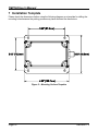
Figure 5 – Mounting Surface Template ................................................................................... 12
Revision 1.2
Page iii