1
Embedded Solutions
20RC01-00 E4 – 2011-01-31
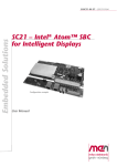
RC1 – Rugged MIPIOS®
Box Computer
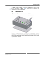
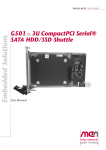
Configuration example (shown with all additional interfaces)
User Manual
®
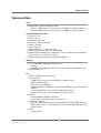
RC1 – Rugged MIPIOS® Box Computer
RC1 – Rugged MIPIOS® Box Computer
The RC1 box computer is a rugged, fanless and maintenance-free control unit for
harsh, mobile, mission-critical applications with or without visualization
requirements in transportation, avionics, industrial automation and medical
engineering.
Two standard models are available: One without a display and one with a 3.5" 4:3
262,144 color display (primarily for service purposes) with a resolution of 640x480
and touch functionality to control the unit.
Both standard models are powered by an Intel® Atom™ Z510 running at 1.1 GHz
and are equipped with 512 MB RAM and a 2GB MicroSD card (a SATA solid-state
drive and Flash memory are optional). All I/O signals are concentrated at the front
side. They include 2 Fast Ethernet (on M12 connectors) and a service interface with
one USB port (master or client), one RS232, a reset input and one GPIO, all
combined on an 8-pin M12 connector. The RC1 offers two slots for additional I/O
purposes for which a number of special SA-Adapter™ kits with M12 connectors are
available. The FPGA-based concept of the RC1 enables easy implementation of
various interfaces (e.g., CAN bus, RS485, IBIS, GPS or binary I/O).
A second power input makes it possible to connect a backup power source (e.g., a
battery) that is automatically used in case of power failure on the main power input.
As a fully EN50155 compliant power class S2 unit, the RC1 remains functional
despite power interruption for up to 10 ms.
The unit's PCI Express® Mini card and SIM card slots can be used to add wireless
functionality like Bluetooth, WLAN, WIMAX, GSM/GPRS, UMTS etc. For this
case, two optional N-Type connectors can be made available at the unit's front panel.
The RC1 is one of the first members of the MIPIOS® family of extremely rugged
IP67 compliant products designed for Ethernet connectivity. The unit is prepared for
wall or DIN-rail mounting. Its robust stainless enclosure is protected against violent
impacts and the whole unit is compliant with IP67. With a typical power
consumption of only 12 W for the total system the design is always realized without
fans, using conduction cooling to spread the dissipated heat to the outside of the
housing. All electronic components are soldered to withstand shock and vibration
and prepared for conformal coating. The standard versions of the RC1 comply with
ISO 7637-2:2004 and the EN 50155, class Tx railway standard, i.e., the units are
able to operate in a -40 to +70°C (+85°C for 10 minutes) environment. The optional
display panel is designed for an operating temperatue of -30 to +70°C with
automatic switch-off of the display at excess temperatures.
MEN Mikro Elektronik GmbH
20RC01-00 E4 – 2011-01-31
2
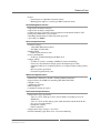
Technical Data
Technical Data
CPU
• Intel® Atom™ processor Z510 or Z530
- Z510: 1.1 GHz processor core frequency, 400 MHz system bus frequency or
- Z530: 1.6 GHz processor core frequency, 533 MHz system bus frequency
Display (06RC01-01 model)
•
•
•
•
•
•
•
•
•
Screen size: 3.5"
Aspect ratio: 4:3
Resolution: 640 x 480
Luminance (cd/m2): 250 cd/m2
Contrast: 400 typ.
Colors: 262,144
Visible screen area: 72 mm x 52.5 mm
Touch functionality to control the RC1 (HMI)
Monitored and controlled by a temperature sensor (automatic switch-off of the
display below -30°C and above +70°C)
• Display and touch functionality fully IP67 compliant!
Memory
• Up to 1 GB DDR2 SDRAM system memory
- Soldered
- 400 MHz or 533 MHz memory bus frequency locked to the FSB frequency
• 2GB MicroSD card
I/O
• All I/O available at front of housing
• Service interface
- 1 USB 2.0 master or client (configurable via BIOS setting)
- UHCI implementation
- Data rates up to 480 Mbits/s
- 1 RS232 or RS485 (half-duplex), redirection for BIOS settings and terminal
function)
- 1 reset input (hardware reset for the Intel® Atom™ CPU)
- All accessible via the same 8-pin M12 connector (female)
• Ethernet
- Two 10/100Base-T Ethernet channels
- Accessible via 4-pin M12 connectors (female)
• Various I/O (optional)
- Up to two additional I/O interfaces (RS232, RS422, RS485, IBIS, CAN bus,
GPS or binary I/O) via various M12 connectors, realized through special SAAdapter™ kits
• Audio
- 1 piezo speaker
MEN Mikro Elektronik GmbH
20RC01-00 E4 – 2011-01-31
3
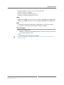
Technical Data
• Power
- Power input via 4-pin M12 connector (male)
- Backup power input via second 4-pin M12 connector (male)
Board Management Control
•
•
•
•
•
•
Supervision of internal voltages
Supervision of display temperature
Control of power sequencing and reset behavior of the Intel® Atom™ CPU
Emergency shutdown in case of failure
Watchdog functionality for CPU with clock generator
Accessible via SMBus
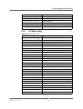
Electrical Specifications
• Isolation voltage:
- 1,500 VDC (Ethernet interface)
- 500 VDC (all other I/O)
• Buffered RTC
- Gold cap for more than 12 h
• Power consumption:
- 12 W typ. (without PCI Express® Mini card)
• Supply voltage:
- 24 VDC (9 to 36 V) according to EN50155 (main and backup)
- Power class S2 (functional despite power interruption up to 10ms)
- Automatic failover to secondary input in case of power failure on the primary
input
- Reverse polarity protection
- Overcurrent protection by fuse
Mechanical Specifications
•
•
•
•
•
•
Dimensions: 220 mm x 130 mm x 70 mm (without connectors)
Prepared for wall or DIN-rail mounting (EN 50022, BS 5584)
Weight: 1.8 kg
Aluminum enclosure
IP67 compliant
Conformal coating on request
Environmental Specifications
• Temperature range (operation):
- -40°C to +70°C, with up to +85°C for 10 minutes according to class Tx
(EN50155)
- -30°C to +70°C for the display panel (with automatic switch-off of the display at excess temperatures)
- Conductive cooling
- Fanless operation
• Temperature range (storage): -40..+85°C
• Relative humidity (operation): max. 95% non-condensing
MEN Mikro Elektronik GmbH
20RC01-00 E4 – 2011-01-31
4
Technical Data
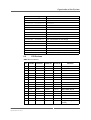
•
•
•
•
Relative humidity (storage): max. 95% non-condensing
Altitude: -300 m to + 3,000 m
Shock: according to EN 50155 (10.2.11)
Vibration: according to EN 50155 (10.2.11)
MTBF
• 06RC01-00: MTBF 103,413 h @ 40°C according to IEC/TR 62380 (RDF 2000)
• 06RC01-01: MTBF 20,981 h @ 40°C according to IEC/TR 62380 (RDF 2000)
EMC
• Conforming to EN 50155, EN 50121-3-2/EN 61000-4-5, ISO 7637-2:2004
• e1 certified by the German Federal Motor Transport Authority
Software Support
• Windows® XP Embedded
- 06RC01-01: Windows® XP Embedded image included (120-day trial version
for evaluation purposes only)
• Linux
- Deliverable with eval Linux pre-installed
• For more information on supported operating system versions and drivers see
online data sheet.
MEN Mikro Elektronik GmbH
20RC01-00 E4 – 2011-01-31
5
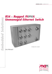
Block Diagram
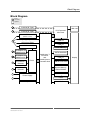
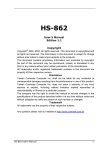
Block Diagram
F
Front
connector
Options
F
F
Antenna (N-Type)
SIM card
PCI Express®
Mini Card
Antenna (N-Type)
USB 2.0
(Master or client)
F
Reset input (opt.: power button)
USB 2.0
GPIO from FPGA
USB 2.0
UART RS232/485
Flash Memory
F
F
SA-Adapter for
additional I/O
SATA HDD/SSD
SA-Adapter for
additional I/O
F
10/100Base-T
Ethernet
F
10/100Base-T
Ethernet
FPGA
Intel® Atom™
Processor
and
Intel® System
Controller Hub
USB 2.0
Display
2GB MicroSD Card
System Memory
DDR2 SDRAM
USB 2.0
F
Power Supply
Touch
F
Piezo Speaker
MEN Mikro Elektronik GmbH
20RC01-00 E4 – 2011-01-31
LVDS
6
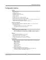
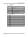
Configuration Options
Configuration Options
Display
•
•
•
•
•
•
•
•
•
Screen size: 3.5"
Aspect ratio: 4:3
Resolution: 640 x 480
Luminance (cd/m2): 250 cd/m2
Contrast: 400 typ.
Colors: 262,144
Visible screen area: 72 mm x 52.5 mm
Touch functionality to control the RC1 (HMI)
Monitored and controlled by a temperature sensor (automatic switch-off of the
display below -30°C and above +70°C)
• Display and touch functionality fully IP67 compliant!
Wireless functionality
• Bluetooth, WLAN, WIMAX, GSM/GPRS, UMTS etc. via respective PCI
Express® Mini card
- PCI Express® Mini card slot features a SIM card slot
- Uses optional N-type antenna connectors
Processor
• Intel® Atom™ processor Z510 or Z530
- Z510: 1.1 GHz processor core frequency, 400 MHz system bus frequency or
- Z530: 1.6 GHz processor core frequency, 533 MHz system bus frequency
Memory
•
•
•
•
Up to 1GB DDR2 SDRAM system memory
MicroSD card (various sizes available)
SATA solid-state drive (various sizes available)
USB Flash solid-state drive (various sizes available)
I/O interfaces
• Various combinations of interfaces with SA-Adapter™ kits via two M12 ports
- RS232 (isolated)
- RS422 (isolated)
- RS485 (isolated)
- IBIS (isolated)
- CAN bus (isolated)
- GPS (isolated)
- Binary I/O (isolated)
• Two N-type connectors for antenna diversity
- Adapter with SIM card slot for optional PCI Express® Mini card
- For WLAN, WIMAX, GSM/GPRS, UMTS etc.
MEN Mikro Elektronik GmbH
20RC01-00 E4 – 2011-01-31
7
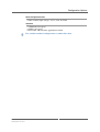
Configuration Options
Electrical Specifications
• Other nominal input voltages: 48, 72, 96 or 110 VDC
Software
• VxWorks® (on request)
• QNX® (on request)
• Deliverable with customer application installed
For available standard configurations see online data sheet.
MEN Mikro Elektronik GmbH
20RC01-00 E4 – 2011-01-31
8
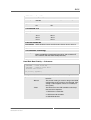
About this Document
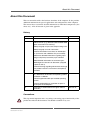
About this Document
This user manual describes the hardware functions of the computer. It also provides
additional information for special applications and configurations of the computer.
The manual does not include detailed information on individual components (data
sheets etc.). A list of literature is given in the appendix.
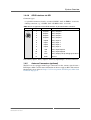
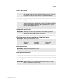
History
Issue
Comments
Date
E1
First issue
2009-09-02
E2
Major update: Incorporated changes from new
product revision (e.g., MicroSD card and SATA SSD
option instead of Flash memory)
2010-11-22
Added paragraph on pressure compensating valve
Added paragraph on earth connection
Removed installation instructions for SA-Adapter
kits (unit comes with additional I/O pre-installed)
Added more detailed information regarding input
voltage and primary/secondary input selection
Added detailed information on connector types
Modified general structure of document (swapped
chapters 3 and 4)
Removed warning regarding electrostatic discharge
(new product revision is not meant to be opened)
Cosmetics
E3
Models without display come without operating sys- 2010-12-15
tem, added basic instructions for operating system
installation via RS232
Clarified supported and/or pre-installed operating
systems
Removed outdated link to installation chapter in
sub-chapter on SA-Adapters.
E4
Dimensions in technical data now given without
connectors
2011-01-31
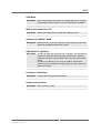
Conventions
!
This sign marks important notes or warnings concerning proper functionality of the
product described in this document. You should read them in any case.
MEN Mikro Elektronik GmbH
20RC01-00 E4 – 2011-01-31
9
About this Document
italics
bold
monospace
hyperlink
Folder, file and function names are printed in italics.
Bold type is used for emphasis.
A monospaced font type is used for hexadecimal numbers, listings, C function
descriptions or wherever appropriate. Hexadecimal numbers are preceded by "0x".
Hyperlinks are printed in blue color.
The globe will show you where hyperlinks lead directly to the Internet, so you can
look for the latest information online.
IRQ#
/IRQ
Signal names followed by "#" or preceded by a slash ("/") indicate that this signal is
either active low or that it becomes active at a falling edge.
in/out
Signal directions in signal mnemonics tables generally refer to the corresponding
board or component, "in" meaning "to the board or component", "out" meaning
"coming from it".
Vertical lines on the outer margin signal technical changes to the previous issue of
the document.
MEN Mikro Elektronik GmbH
20RC01-00 E4 – 2011-01-31
10
About this Document
Legal Information
MEN Mikro Elektronik reserves the right to make changes without further notice to any products herein. MEN makes no
warranty, representation or guarantee regarding the suitability of its products for any particular purpose, nor does MEN assume
any liability arising out of the application or use of any product or circuit, and specifically disclaims any and all liability,
including without limitation consequential or incidental damages.
"Typical" parameters can and do vary in different applications. All operating parameters, including "Typicals" must be
validated for each customer application by customer's technical experts.
MEN does not convey any license under its patent rights nor the rights of others.
Unless agreed otherwise, MEN products are not designed, intended, or authorized for use as components in systems intended
for surgical implant into the body, or other applications intended to support or sustain life, or for any other application in which
the failure of the MEN product could create a situation where personal injury or death may occur. Should Buyer purchase or
use MEN products for any such unintended or unauthorized application, Buyer shall indemnify and hold MEN and its officers,
employees, subsidiaries, affiliates, and distributors harmless against all claims, costs, damages, and expenses, and reasonable
attorney fees arising out of, directly or indirectly, any claim of personal injury or death associated with such unintended or
unauthorized use, even if such claim alleges that MEN was negligent regarding the design or manufacture of the part.
Unless agreed otherwise, the products of MEN Mikro Elektronik are not suited for use in nuclear reactors or for application in
medical appliances used for therapeutical purposes. Application of MEN products in such plants is only possible after the user
has precisely specified the operation environment and after MEN Mikro Elektronik has consequently adapted and released the
product.
ESM™, ESMini™, MDIS™, MDIS4™, MENMON™, M-Module™, M-Modules™, SA-Adapter™, SA-Adapters™,
UBox™, USM™ and the MBIOS logo are trademarks of MEN Mikro Elektronik GmbH. PC-MIP® is a registered trademark
of MEN Micro, Inc. and SBS Technologies, Inc. MEN Mikro Elektronik®, ESMexpress®, MIPIOS® and the MEN logo are
registered trademarks of MEN Mikro Elektronik GmbH.
Altera®, Arria®, Avalon®, Cyclone®, Nios® and Quartus® are registered trademarks of Altera Corp. Intel® Atom™ and
Intel® Core™ are trademarks of Intel, Inc. Celeron®, Intel®, Pentium® and Xeon® are registered trademarks of Intel, Inc.
Microsoft® and Windows® are registered trademarks of Microsoft Corp. Windows® Vista™ is a trademark of Microsoft Corp.
PCI Express® and PCIe® are registered trademarks of PCI-SIG. QNX® is a registered trademark of QNX Ltd. Tornado® and
VxWorks® are registered trademarks of Wind River Systems, Inc.
All other products or services mentioned in this publication are identified by the trademarks, service marks, or product names
as designated by the companies who market those products. The trademarks and registered trademarks are held by the
companies producing them. Inquiries concerning such trademarks should be made directly to those companies. All other brand
or product names are trademarks or registered trademarks of their respective holders.
Information in this document has been carefully checked and is believed to be accurate as of the date of publication; however,
no responsibility is assumed for inaccuracies. MEN Mikro Elektronik accepts no liability for consequential or incidental
damages arising from the use of its products and reserves the right to make changes on the products herein without notice to
improve reliability, function or design. MEN Mikro Elektronik does not assume any liability arising out of the application or
use of the products described in this document.
Copyright © 2011 MEN Mikro Elektronik GmbH. All rights reserved.
Please recycle
Germany
MEN Mikro Elektronik GmbH
Neuwieder Straße 5-7
90411 Nuremberg
Phone +49-911-99 33 5-0
Fax +49-911-99 33 5-901
E-mail [email protected]
www.men.de
MEN Mikro Elektronik GmbH
20RC01-00 E4 – 2011-01-31
France
MEN Mikro Elektronik SA
18, rue René Cassin
ZA de la Châtelaine
74240 Gaillard
Phone +33 (0) 450-955-312
Fax +33 (0) 450-955-211
E-mail [email protected]
www.men-france.fr
USA
MEN Micro, Inc.
24 North Main Street
Ambler, PA 19002
Phone (215) 542-9575
Fax (215) 542-9577
E-mail [email protected]
www.menmicro.com
11
Contents
Contents
1 System Overview . . . . . . . . . . . . . . . . . . . . . . . . . . . . . . . . . . . . . . . . . . . . . . .
1.1 Layout of the RC1 . . . . . . . . . . . . . . . . . . . . . . . . . . . . . . . . . . . . . . . .
1.2 Pressure Compensating Valve . . . . . . . . . . . . . . . . . . . . . . . . . . . . . . .
1.3 Earth Connection . . . . . . . . . . . . . . . . . . . . . . . . . . . . . . . . . . . . . . . . .
1.4 Interfaces . . . . . . . . . . . . . . . . . . . . . . . . . . . . . . . . . . . . . . . . . . . . . . .
1.4.1
Power Input . . . . . . . . . . . . . . . . . . . . . . . . . . . . . . . . . . . . . .
1.4.2
Ethernet Interface . . . . . . . . . . . . . . . . . . . . . . . . . . . . . . . . .
1.4.3
Service Interface (USB / RS232 / reset input) . . . . . . . . . . .
1.4.4
Additional I/O via SA-Adapter kits (optional) . . . . . . . . . . .
1.4.5
Antenna Connectors (optional) . . . . . . . . . . . . . . . . . . . . . . .
1.5 Audio Interface . . . . . . . . . . . . . . . . . . . . . . . . . . . . . . . . . . . . . . . . . .
1.6 Front-Panel Status LEDs . . . . . . . . . . . . . . . . . . . . . . . . . . . . . . . . . . .
1.6.1
Power Supply Status LEDs . . . . . . . . . . . . . . . . . . . . . . . . . .
1.6.2
Ethernet Port Status LEDs . . . . . . . . . . . . . . . . . . . . . . . . . .
1.6.3
Service LEDs . . . . . . . . . . . . . . . . . . . . . . . . . . . . . . . . . . . .
16
16
16
16
17
17
18
19
20
22
23
23
23
23
23
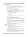
2 Getting Started . . . . . . . . . . . . . . . . . . . . . . . . . . . . . . . . . . . . . . . . . . . . . . . .
2.1 Installing Operating System and Driver Software. . . . . . . . . . . . . . . .
2.1.1
Model without a display (06RC01-00) . . . . . . . . . . . . . . . . .
2.1.2
Model with a display (06RC01-01) . . . . . . . . . . . . . . . . . . .
2.2 Mounting the RC1 . . . . . . . . . . . . . . . . . . . . . . . . . . . . . . . . . . . . . . . .
25
25
25
25
26
3 Functional Description . . . . . . . . . . . . . . . . . . . . . . . . . . . . . . . . . . . . . . . . . .
3.1 Reset . . . . . . . . . . . . . . . . . . . . . . . . . . . . . . . . . . . . . . . . . . . . . . . . . .
3.2 Real-Time Clock . . . . . . . . . . . . . . . . . . . . . . . . . . . . . . . . . . . . . . . . .
3.3 Memory . . . . . . . . . . . . . . . . . . . . . . . . . . . . . . . . . . . . . . . . . . . . . . . .
3.3.1
DRAM System Memory . . . . . . . . . . . . . . . . . . . . . . . . . . . .
3.3.2
Boot Flash . . . . . . . . . . . . . . . . . . . . . . . . . . . . . . . . . . . . . . .
3.3.3
EEPROM. . . . . . . . . . . . . . . . . . . . . . . . . . . . . . . . . . . . . . . .
3.3.4
Mass Storage . . . . . . . . . . . . . . . . . . . . . . . . . . . . . . . . . . . . .
3.4 Graphics. . . . . . . . . . . . . . . . . . . . . . . . . . . . . . . . . . . . . . . . . . . . . . . .
3.5 Board Supervision . . . . . . . . . . . . . . . . . . . . . . . . . . . . . . . . . . . . . . . .
3.6 Display Temperature Supervision . . . . . . . . . . . . . . . . . . . . . . . . . . . .
3.7 Power Supply Status Monitoring. . . . . . . . . . . . . . . . . . . . . . . . . . . . .
3.8 Enabling and Disabling the PCI Express Mini Card . . . . . . . . . . . . . .
28
28
28
28
28
28
28
28
28
29
29
29
30
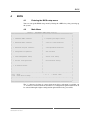
4 BIOS . . . . . . . . . . . . . . . . . . . . . . . . . . . . . . . . . . . . . . . . . . . . . . . . . . . . . . . . .
4.1 Entering the BIOS setup menu . . . . . . . . . . . . . . . . . . . . . . . . . . . . . .
4.2 Main Menu . . . . . . . . . . . . . . . . . . . . . . . . . . . . . . . . . . . . . . . . . . . . .
4.3 Standard CMOS Features . . . . . . . . . . . . . . . . . . . . . . . . . . . . . . . . . .
4.4 Advanced BIOS Features . . . . . . . . . . . . . . . . . . . . . . . . . . . . . . . . . .
4.5 Advanced Chipset Features . . . . . . . . . . . . . . . . . . . . . . . . . . . . . . . . .
4.6 Integrated Peripherals . . . . . . . . . . . . . . . . . . . . . . . . . . . . . . . . . . . . .
31
31
31
32
34
38
40
MEN Mikro Elektronik GmbH
20RC01-00 E4 – 2011-01-31
12
Contents
4.7
4.8
4.9
4.10
4.11
4.12
4.13
4.14
4.15
Power Management Setup . . . . . . . . . . . . . . . . . . . . . . . . . . . . . . . . . .
PNP/PCI Configurations . . . . . . . . . . . . . . . . . . . . . . . . . . . . . . . . . . .
PC Health Status . . . . . . . . . . . . . . . . . . . . . . . . . . . . . . . . . . . . . . . . .
Frequency/Voltage Control . . . . . . . . . . . . . . . . . . . . . . . . . . . . . . . . .
Load Fail-Safe Defaults. . . . . . . . . . . . . . . . . . . . . . . . . . . . . . . . . . . .
Load Optimized Defaults. . . . . . . . . . . . . . . . . . . . . . . . . . . . . . . . . . .
Set Password . . . . . . . . . . . . . . . . . . . . . . . . . . . . . . . . . . . . . . . . . . . .
Save & Exit Setup . . . . . . . . . . . . . . . . . . . . . . . . . . . . . . . . . . . . . . . .
Exit without Saving . . . . . . . . . . . . . . . . . . . . . . . . . . . . . . . . . . . . . . .
44
46
48
48
49
49
49
49
49
5 Organization of the System . . . . . . . . . . . . . . . . . . . . . . . . . . . . . . . . . . . . . .
5.1 Memory Mappings . . . . . . . . . . . . . . . . . . . . . . . . . . . . . . . . . . . . . . .
5.1.1
Processor View of the Memory Map. . . . . . . . . . . . . . . . . . .
5.1.2
I/O Memory Map . . . . . . . . . . . . . . . . . . . . . . . . . . . . . . . . .
5.2 PCI Devices . . . . . . . . . . . . . . . . . . . . . . . . . . . . . . . . . . . . . . . . . . . . .
5.3 SMBus Devices . . . . . . . . . . . . . . . . . . . . . . . . . . . . . . . . . . . . . . . . . .
5.4 Interrupt Mapping . . . . . . . . . . . . . . . . . . . . . . . . . . . . . . . . . . . . . . . .
50
50
50
51
52
53
53
6 Maintenance . . . . . . . . . . . . . . . . . . . . . . . . . . . . . . . . . . . . . . . . . . . . . . . . . . 54
6.1 Cleaning the Display . . . . . . . . . . . . . . . . . . . . . . . . . . . . . . . . . . . . . . 54
6.2 Fuse Protection . . . . . . . . . . . . . . . . . . . . . . . . . . . . . . . . . . . . . . . . . . 54
7 Appendix . . . . . . . . . . . . . . . . . . . . . . . . . . . . . . . . . . . . . . . . . . . . . . . . . . . . .
7.1 Pin Assignment of PCI Express Mini Card Connector . . . . . . . . . . . .
7.2 Literature and Web Resources . . . . . . . . . . . . . . . . . . . . . . . . . . . . . . .
7.2.1
PCI Express Mini Card . . . . . . . . . . . . . . . . . . . . . . . . . . . . .
7.3 Finding out the Board’s Article Number, Revision
and Serial Number . . . . . . . . . . . . . . . . . . . . . . . . . . . . . . . . . . . . . . . .
MEN Mikro Elektronik GmbH
20RC01-00 E4 – 2011-01-31
55
55
56
56
57
13
Figures
Figure 1. The RC1 – front view (shown with all optional interfaces
and display). . . . . . . . . . . . . . . . . . . . . . . . . . . . . . . . . . . . . . . . . . . . . .
Figure 2. Earth connection and pressure compensating valve . . . . . . . . . . . . . . .
Figure 3. Mounting the RC1 to the DIN-rail mounting plate . . . . . . . . . . . . . . .
Figure 4. Mounting the RC1 to the wall-mounting plate. . . . . . . . . . . . . . . . . . .
Figure 5. Label giving the product’s article number, revision
and serial number . . . . . . . . . . . . . . . . . . . . . . . . . . . . . . . . . . . . . . . . .
MEN Mikro Elektronik GmbH
20RC01-00 E4 – 2011-01-31
16
16
26
27
57
14
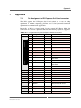
Tables
Table 1.
Table 2.
Table 3.
Table 4.
Table 5.
Table 6.
Table 7.
Table 8.
Table 9.
Table 10.
Table 11.
Table 12.
Table 13.
Table 14.
Table 15.
Table 16.
Table 17.
Table 18.
Table 19.
Table 20.
Table 21.
MEN Mikro Elektronik GmbH
20RC01-00 E4 – 2011-01-31
Voltage thresholds for 24 VDC and 110 VDC PSUs. . . . . . . . . . . . . .
Pin assignment of the power supply
4-pin male M12 connectors . . . . . . . . . . . . . . . . . . . . . . . . . . . . . . . . .
Pin assignment of the Ethernet
4-pin female M12 connectors . . . . . . . . . . . . . . . . . . . . . . . . . . . . . . . .
Pin assignment of the service interface
8-pin male M12 connector . . . . . . . . . . . . . . . . . . . . . . . . . . . . . . . . . .
Pin assignment of the RS232 interface
5-pin female M12 connector. . . . . . . . . . . . . . . . . . . . . . . . . . . . . . . . .
Pin assignment of the RS422/RS485 interface
5-pin female M12 connector. . . . . . . . . . . . . . . . . . . . . . . . . . . . . . . . .
Pin assignment of the IBIS master interface
5-pin male M12 connector . . . . . . . . . . . . . . . . . . . . . . . . . . . . . . . . . .
Pin assignment of the IBIS slave interface
5-pin female M12 connector. . . . . . . . . . . . . . . . . . . . . . . . . . . . . . . . .
Pin assignment of the CAN bus interface
5-pin male M12 connector . . . . . . . . . . . . . . . . . . . . . . . . . . . . . . . . . .
Pin assignment of the GPIO interface
12-pin female M12 connector. . . . . . . . . . . . . . . . . . . . . . . . . . . . . . . .
Power supply status LEDs . . . . . . . . . . . . . . . . . . . . . . . . . . . . . . . . . .
Ethernet port status LEDs. . . . . . . . . . . . . . . . . . . . . . . . . . . . . . . . . . .
Service LEDs . . . . . . . . . . . . . . . . . . . . . . . . . . . . . . . . . . . . . . . . . . . .
Error codes signaled by the BMC via LED flashes . . . . . . . . . . . . . . .
Power Supply Status and PCI Express Mini Card
Enable/Disable Byte . . . . . . . . . . . . . . . . . . . . . . . . . . . . . . . . . . . . . . .
Memory map – processor view . . . . . . . . . . . . . . . . . . . . . . . . . . . . . .
Memory map – I/O . . . . . . . . . . . . . . . . . . . . . . . . . . . . . . . . . . . . . . . .
PCI Devices . . . . . . . . . . . . . . . . . . . . . . . . . . . . . . . . . . . . . . . . . . . . .
SMBus devices . . . . . . . . . . . . . . . . . . . . . . . . . . . . . . . . . . . . . . . . . . .
Interrupts. . . . . . . . . . . . . . . . . . . . . . . . . . . . . . . . . . . . . . . . . . . . . . . .
Pin assignment of 52-pin PCI Express Mini Card connector. . . . . . . .
17
17
18
19
20
20
21
21
21
22
23
23
23
24
29
50
51
52
53
53
55
15
System Overview
1
System Overview
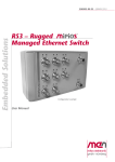
1.1
Layout of the RC1
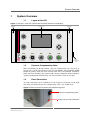
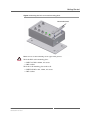
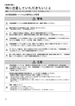
Figure 1. The RC1 – front view (shown with all optional interfaces and display)
Detachable bezel
Detachable
bezel
Display panel
SA 1
ANT 1
SA 2
ANT 2
PWR ACT
PWR ACT
S1 S2
LNK ACT
LNK ACT
PRIM PWR
SEC PWR
SERVICE
ETH 1
ETH 2
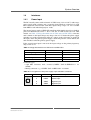
1.2
Pressure compensating valve
Pressure Compensating Valve
The sealed housing of the RC1 makes a pressure compensating valve necessary to
prevent stress on the unit’s housing seals. Its hydrophobic and oleophobic ePTFE
membrane protects from the unit’s interior from water and common automotive
fluids and resists blocking after contact with common automotive fluids. It protects
against contamination from dirt, dust, salt and road debris (down to 0.07 µm).
1.3
Earth Connection
An earth connection can be established via the respective screw hole on the right
side of the unit (below the pressure compensating valve). Use an M4 screw.
Figure 2. Earth connection and pressure compensating valve
Pressure compensating valve
Screw hole for earth connection
MEN Mikro Elektronik GmbH
20RC01-00 E4 – 2011-01-31
16
System Overview
1.4
Interfaces
1.4.1
Power Input
The RC1 usually comes with an internal 24 VDC nom. (14.4 to 33.6 V) wide-range
power supply with a primary and a secondary input. Both are connected via 4-pin
M12 connectors. RC1 models with other input voltage ranges are also available
from MEN to suit individual projects’ needs.
The internal power supply is EN50155 compliant which implies that it has a built-in
power-on threshold of 0.7xUn = 16.8 V for the 24 VDC model (for 110 VDC
models, see Table 1, Voltage thresholds for 24 VDC and 110 VDC PSUs). Once the
unit is turned on, the input voltage may drop as low as 12 V before the power supply
switches over to the second power input (if a voltage in the valid range is applied to
this input). Once the primary power supply is back and good for at least 200 ms, the
unit switches back to the primary power supply.
If the second power input is not used, the input voltage on the primary input may
drop as low as 9 V.
Table 1. Voltage thresholds for 24 VDC and 110 VDC PSUs
PSU:
24 VDC nom.
110 VDC nom.
Input voltage range
9..36V
77..150V
Power-on threshold
16.8V
77V
Power change-over threshold
12V
66V
Power-off threshold
9V
66V
Connector types:
• 4-pin M12 connector, male, A-coded (CONEC "SAL-12-FSH4-P12-9" 4301066)
• Mating connector: e.g., CONEC "SAL-12-RK4-2/A1" 43-10020
Table 2. Pin assignment of the power supply 4-pin male M12 connectors
2
3
Name
Description
1
+VBAT
Positive input
2
+VBAT
Positive input
3
-VBAT
Negative input
4
-VBAT
Negative input
1
4
MEN Mikro Elektronik GmbH
20RC01-00 E4 – 2011-01-31
Pin
17
System Overview
1.4.2
Ethernet Interface
The RC1 comes with two Fast Ethernet ports on 4-pin female M12 connectors.
Connector types:
• 4-pin M12 connector, female, D-coded (CONEC "SAL-12D-FKH4.2-P12-9"
43-01248)
• Mating connector: e.g., Harting 21032811405 R410925
Table 3. Pin assignment of the Ethernet 4-pin female M12 connectors
1
4
Pin
Name
Description
1
TX+
Transmitter positive output
2
RX+
Receiver positive input
3
TX-
Transmitter negative output
4
RX-
Receiver negative input
2
3
The Ethernet controller has its own EEPROM to store the MAC address etc.
!
The unique MAC address is set at the factory and should not be changed. Any
attempt to change this address may create node or bus contention and thereby render
the unit inoperable. The MAC addresses on the RC1 are:
• LAN0: 0x 00 C0 3A 02 8x xx - 0x 00 C0 3A 02 BF FF
• LAN1: 0x 00 C0 3A 02 Cx xx - 0x 00 C0 3A 02 FF FF
where "00 C0 3A" is the MEN vendor code, "02" is the MEN product code. The
last four digits depend on the interface and the serial number of the RC1’s internal
SBC board. The serial number is added to the offset, for example for LAN0:
• Serial number 0042: 0x xx xx = 0x8000 + 0x 00 2A = 0x 80 2A.
!
Please note that due to the internal structure of the RC1, the serial number coded in
the MAC addresses is different from the serial number of the entire RC1 unit. For
the unit’s overall serial number please refer to Chapter 7.3 Finding out the Board’s
Article Number, Revision and Serial Number on page 57.
MEN Mikro Elektronik GmbH
20RC01-00 E4 – 2011-01-31
18
System Overview
1.4.3
Service Interface (USB / RS232 / reset input)
The service interface combines several signals on one 8-pin male M12 connector.
Connector types:
• 8-pin M12 connector, female, A-coded (CONEC "SAL-12-FKH8-P12-9" 4301064)
• Mating connector: e.g., CONEC "SAL-12S-RS8-2/G3" 43-10980
Table 4. Pin assignment of the service interface 8-pin male M12 connector
7
8
1
2
Pin
Name
Description
1
+5V
USB supply voltage
2
RxD
RS232 or RS485 receive
3
TxD
RS232 or RS485 transmit
4
USB7-
USB Host/Device Mode
5
USB7+
USB Host/Device Mode
6
Reset_BTN
Internal pull-up to 3.3 V
7
FPGA GPIO Connected to FPGA GPIO 0 on RC1 CPU
(pull-up to 3.3 V)
6
5
3
4
8
!
VSS
Signal ground
The maximum USB current is 500mA. To avoid overheating, make sure to avoid the
maximum load of 2.5W when operating the RC1 close to the unit’s maximum
operating temperature!
The reset is active low, filtered against noise and ESD protected.
MEN Mikro Elektronik GmbH
20RC01-00 E4 – 2011-01-31
19
System Overview
1.4.4
Additional I/O via SA-Adapter kits (optional)
The RC1 offers up to two additional interfaces that can be accessed via special SAAdapter kits. These kits use various types of M12 connectors for their individual I/O
functions.
1.4.4.1
RS232 Interface
Connector types:
• 5-pin M12 connector, female, A-coded (CONEC "SAL-12-FKH5" 43-01004)
• Mating connector: e.g., CONEC "SAL-12S-RS5.1-2/G3" 43-10360
Table 5. Pin assignment of the RS232 interface 5-pin female M12 connector
1
5
4
Pin
Name
Description
1
-
2
TxD
Transmit data
3
GND
Isolated ground
4
RxD
Receive data
5
-
(not connected)
2
3
1.4.4.2
(not connected)
RS422/RS485 Interface
Connector types:
• 5-pin M12 connector, female, A-coded (CONEC "SAL-12-FKH5" 43-01004)
• Mating connector: e.g., CONEC "SAL-12S-RS5.1-2/G3" 43-10360
Table 6. Pin assignment of the RS422/RS485 interface 5-pin female M12 connector
Pin
TxD- or
Transmit data (full duplex) or
TxD- / RxD- transmit / receive data (half duplex)
2
TxD+ or
Transmit data (full duplex) or
TxD+ / RxD+ transmit / receive data (half duplex)
1
2
3
MEN Mikro Elektronik GmbH
20RC01-00 E4 – 2011-01-31
Description
1
5
4
Name
3
RxD-
Receive data (full duplex)
4
RxD+
Receive data (full duplex)
5
- (shield)
(not connected (shield))
20
System Overview
1.4.4.3
IBIS Master Interface
Connector types:
• 5-pin M12 connector, male, A-coded (CONEC "SAL-12-FSH5" 43-01013)
• Mating connector: e.g., CONEC "SAL-12S-RK5.1-2/G3" 43-10344
Table 7. Pin assignment of the IBIS master interface 5-pin male M12 connector
Pin
1
2
3
1
4
5
1.4.4.4
Name
24V
2
MISO+
3
24V_GND
4
MOSI+
5
24V_GND
Description
24V power supply
current-limited to 1.5A by a fuse
IBIS master in, slave out
Ground
IBIS master out, slave in
Ground
IBIS Slave Interface
Connector types:
• 5-pin M12 connector, female, A-coded (CONEC "SAL-12-FKH5" 43-01004)
• Mating connector: e.g., CONEC "SAL-12S-RS5.1-2/G3" 43-10360
Table 8. Pin assignment of the IBIS slave interface 5-pin female M12 connector
1
5
4
Pin
Name
1
-
2
MOSI+
3
24V_GND
4
MISO+
5
24V_GND
Description
(not connected)
IBIS master out, slave in
2
3
1.4.4.5
Ground
IBIS master in, slave out
Ground
CAN Bus Interface
Connector types:
• 5-pin M12 connector, male, A-coded (CONEC "SAL-12-FSH5" 43-01013)
• Mating connector: e.g., CONEC "SAL-12S-RK5.1-2/G3" 43-10344
Table 9. Pin assignment of the CAN bus interface 5-pin male M12 connector
2
3
Name
Description
1
-
2
CAN L-R
3
CAN GND
4
CAN H
CAN data line H
5
CAN L
CAN data line L
(not connected)
CAN termination resistance
1
4
MEN Mikro Elektronik GmbH
20RC01-00 E4 – 2011-01-31
Pin
CAN isolated ground
5
21
System Overview
1.4.4.6
GPIO Interface via SPI
Connector types:
• 12-pin M12 connector, female, A-coded (CONEC "SAL-12-FKH12" 43-01343)
• Mating connector: e.g., CONEC "SAL-12S-RK12-2/G3" 43-11280
Table 10. Pin assignment of the GPIO interface 12-pin female M12 connector
10
9 1
8
12
7
6
Pin
Name
Description
1
Output0
Binary output 0
2
Output1
Binary output 1
3
Output2
Binary output 2
4
Output3
Binary output 3
5
Input0
Binary input 0
6
Input1
Binary input 1
7
Input2
Binary input 2
8
Input3
Binary input 3
9
IO0
Binary input/output 5
10
IO1
Binary input/output 6
11
VCC
Binary output pull-up voltage up to 28.8V
12
GND
Ground
2
3
5 4
11
Note: Binary input 4, binary output 4 and binary input/output 7 are not connected.
1.4.5
Antenna Connectors (optional)
The RC1 can be equipped with N-type connectors for the antenna signals from a
PCI Express Mini card. For more information on how to equip an RC1 with wireless
functionality please refer to Chapter 7.1 Pin Assignment of PCI Express Mini Card
Connector on page 55.
MEN Mikro Elektronik GmbH
20RC01-00 E4 – 2011-01-31
22
System Overview
1.5
Audio Interface
The RC1 features a small piezo speaker behind its front panel which is controlled by
an audio codec. It can be used for different alarm tones and service messages.
1.6
Front-Panel Status LEDs
The RC1 features a total of ten status LEDs at its front panel: Four for the power
supply status, four for the Ethernet port status and two additional service LEDs.
1.6.1
Power Supply Status LEDs
Each of the two power supply ports provides two LEDs to display its status (PWR
and ACT). The LEDs act as described in the following table.
Table 11. Power supply status LEDs
LED
Description
PWR
Input power status (ON = valid range)
ACT
Power supply input status (ON = input active)
1.6.2
Ethernet Port Status LEDs
Each of the two Ethernet user ports provides two LEDs to display its status (LNK
and ACT). The LEDs act as described in the following table.
Table 12. Ethernet port status LEDs
LED
Description
LNK
Ethernet link status (ON = link established)
ACT
Ethernet traffic activity status (ON = Ethernet traffic running)
1.6.3
Service LEDs
Table 13. Service LEDs
LED
Description
S1
Board management controller LED
S2
FPGA GPIO LED
After powering up, the board management controller software can use the LED
connected to it to indicate the last occurred error. Depending on the error code, the
status LED will flash for a defined number of times and pause for one second until
the system is restarted or completely powered off. The supported error codes are as
follows:
MEN Mikro Elektronik GmbH
20RC01-00 E4 – 2011-01-31
23
System Overview
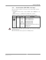
Table 14. Error codes signaled by the BMC via LED flashes
Number of
flashes
Error
Description
1
XM01BCI_ERR_CTSTRPHC_SHTDWN
Catastrophic shutdown
2
XM01BCI_ERR_INP_TOO_LOW
Input voltage too low
3
XM01BCI_ERR_INP_TOO_HIGH
Input voltage too high
4
XM01BCI_ERR_NO_ATX_PWR_OK
ATX_PWR_OK Failure
5
XM01BCI_ERR_NO_PWRGD_5130_1
LVL_1_PWRGD Failure
6
XM01BCI_ERR_NO_DDRVR_PWRGD
DDRVR_PWRGD Failure
7
XM01BCI_ERR_NO_PWRGD_5130_2
LVL_2_PWRGD Failure
8
XM01BCI_ERR_NO_PM_CPU_PWRGD
CPU_PWRGD Failure
9
XM01BCI_ERR_BIOS_TIMEOUT_1
First time BIOS live sign timed out
10
XM01BCI_ERR_BIOS_TIMEOUT_2
Second time BIOS live sign timed out
11
XM01BCI_ERR_BIOS_TIMEOUT_3
Third time BIOS live sign timed out
12
XM01BCI_ERR_BIOS_TIMEOUT_4
Forth time BIOS live sign timed out
13
XM01BCI_ERR_CPU_RST_TIMEOUT
CPU Reset deassert timeout
255
XM01BCI_INVALID_MAIN_STATE
Invalid BMC main state
The FPGA GPIO LED has no pre-defined function and can be incorporated into
applications as needed via the RC1’s GPIO controller.
MEN Mikro Elektronik GmbH
20RC01-00 E4 – 2011-01-31
24
Getting Started
2
Getting Started
2.1
Installing Operating System and Driver Software
The RC1 supports Windows® XP Embedded, Linux, VxWorks® (on request) and
QNX® (on request).
You can find any software available on MEN’s website.
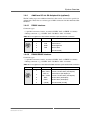
2.1.1
Model without a display (06RC01-00)
Standard RC1 models without a display are delivered without a pre-installed
operating system. To install operating system software, connect a terminal to the
standard RS232 interface available via the service connector.
Set your terminal to the following protocol:
-
115,200 baud data transmission rate
8 data bits
1 stop bit
No parity
Please refer to the respective manufacturer's documentation on how to install
operating system software!
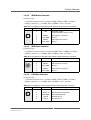
2.1.2
Model with a display (06RC01-01)
Standard RC1 models with a display come with a 120-day trial version of
Windows® XP Embedded and all necessary drivers pre-installed on the MicroSD
card.
During the first power up of the system, the resealing process of the XP Embedded
image will be started automatically, including a system reboot. This will take
approximately 5 minutes. No action on behalf of the user is necessary at this time.
The 120-day trial period starts the moment the resealing process has finished setting
up the system.
Please note that the gold-cap-powered internal clock of the RC1 is used to
determine how much of the trial period remains.
The following events can cause the trial period to end prematurely:
!
• The BIOS time is modified.
• The Windows® time is modified.
• The CPU is separated from the carrier board (the gold cap is located on the carrier board, so the CPU’s internal clock is no longer buffered).
• A BIOS update has unforeseen side-effects.
Should any of this happen and render the trial version of Windows® XP Embedded
unusable prematurely, please contact MEN.
A board support package (BSP) containing all the necessary, hardware-specific
components to create an individualized Windows® XP Embedded is available on
MEN’s website. A complete log of the standard Windows® XP Embedded image
used on the RC1 is available from MEN on request.
MEN Mikro Elektronik GmbH
20RC01-00 E4 – 2011-01-31
25
Getting Started
An MDIS5 installset (13MM01-77) containing all MDIS driver packages for the
RC1 is also available on MEN's website. Please refer to the installset's user
documentation for a detailed description.
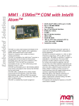
2.2
Mounting the RC1
Figure 3. Mounting the RC1 to the DIN-rail mounting plate
Detachable bezel
The RC1 is designed for mounting using one of two mounting plates, a DIN-rail
mounting plate or a wall-mounting plate (available separately from MEN). To attach
the unit to the mounting plate, remove the detachable bezel at the sides of the front
panel to access the four holes (two on each side) reserved for the necessary screws
as pictured above and below.
MEN Mikro Elektronik GmbH
20RC01-00 E4 – 2011-01-31
26
Getting Started
Figure 4. Mounting the RC1 to the wall-mounting plate
Detachable bezel
Make sure to use the following screw types in the process.
!
To fix the RC1 to the mounting plate:
• 4 DIN 7985 M4 x 20mm, A2 screws
• 4 M4 washers
To fix the wall-mounting plate to the wall:
• 4 DIN7985 M5 x min. 12mm, A2 screws
• 4 M5 washers
MEN Mikro Elektronik GmbH
20RC01-00 E4 – 2011-01-31
27
Functional Description
3
Functional Description
3.1
Reset
The RC1 generates its own reset signal. You can wake it up from reset state by
externally switching the power supply off and on.
3.2
Real-Time Clock
The supply voltage for the RTC is buffered with an external gold cap for a minimum
of 12 hours.
3.3
Memory
3.3.1
DRAM System Memory
The RC1 provides up to 1 GB on-board, soldered DDR2 (double data rate)
SDRAM. The memory bus is 64 bits wide (one channel) and operates with up to
533 MHz.
The RC1 supports memory down technology. The memory is not realized with
complete modules. Instead single memory chips with a maximum of 2 Gbit per chip
are used.
3.3.2
Boot Flash
The RC1 has an 16-Mbit SPI Flash implemented as on-board Flash for BIOS and
FPGA data.
3.3.3
EEPROM
The board has a 4-kbit serial EEPROM. The 4-kbit address space is divided into a 2kbit block for customer specific data and another 2-kbit block for factory data. See
Table 19, SMBus devices on page 53.
3.3.4
Mass Storage
The standard RC1 models are equipped with a 2GB MicroSD card. A 2.5" SATA
solid-state drive and USB NAND Flash memory are optional.
3.4
Graphics
The graphics core of the RC1 provides an LVDS interface with a 112MHz
maximum pixel clock and 18 bits pixel color depth.
MEN Mikro Elektronik GmbH
20RC01-00 E4 – 2011-01-31
28
Functional Description
3.5
Board Supervision
The RC1’s CPU provides an intelligent board management controller (BMC) with
the following main features:
•
•
•
•
•
Control of power sequencing and reset behavior of the Intel Atom CPU
Supervision of CPU supply voltage (+5V)
Emergency shutdown in case of failure
Watchdog functionality for CPU
Accessible via SMBus
The watchdog device monitors the board on operating system level. If enabled, the
watchdog must be triggered by application software. If the trigger is overdue, the
watchdog initiates a board reset and this way can put the system back into operation
when the software hangs.
The watchdog uses a configurable time interval or is disabled. Settings are made
through BIOS or via an MEN software driver.
In addition, the RC1 uses a National LM95245 device to measure the CPU die
temperature and the local board temperature.
3.6
Display Temperature Supervision
The temperature supervision is carried out by the temperature sensor LM50. The
LM50 is a precision integrated-circuit temperature sensor that can sense a -40°C to
+125°C temperature range. The display is automatically switched off at
temperatures below -30°C and above +70°C.
3.7
Power Supply Status Monitoring
It is possible to monitor the power input status by reading back the status of the
power LEDs via SMBus. A read access to 0x40 will give the following result (all
bits except bit 4 are read only!):
Table 15. Power Supply Status and PCI Express Mini Card Enable/Disable Byte
Bit
Description
0
0: Main power supply is in use and input voltage is OK
1: Main power supply is not used, input voltage not OK
1
0: Backup power supply is in use
1: Backup power supply is not in use
2
0: Backup power supply input voltage is OK
1: Backup power supply input voltage not OK
3
Not used
4
0: PCI Express Mini Card power is disabled
1: PCI Express Mini Card power is enabled
5
Not used
6
Not used
7
Not used
MEN Mikro Elektronik GmbH
20RC01-00 E4 – 2011-01-31
29
Functional Description
3.8
Enabling and Disabling the PCI Express Mini Card
Sometimes it might become necessary to reset the PCI Express Mini Card. For this
purpose, simply disable the power for the card by writing 0x00 to SMBus address
0x40. Then re-enable power by writing 0x10 to the same address. The status of the
PCI Express Mini Card power supply can be read back from this address (see Table
15, Power Supply Status and PCI Express Mini Card Enable/Disable Byte).
MEN Mikro Elektronik GmbH
20RC01-00 E4 – 2011-01-31
30
BIOS
4
BIOS
4.1
Entering the BIOS setup menu
You can start up the BIOS setup menu by hitting the <DEL> key after powering up
the system.
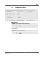
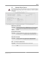
4.2
Main Menu
Phoenix - AwardBIOS CMOS Setup Utility
+=======================================+======================================+
|
|
|
|
|
|
| > Standard CMOS Features
| > Frequency/Voltage Control
|
|
|
|
|
|
|
| > Advanced BIOS Features
|
Load Fail-Safe Defaults
|
|
|
|
|
|
|
| > Advanced Chipset Features
|
Load Optimized Defaults
|
|
|
|
|
|
|
| > Integrated Peripherals
|
Set Password
|
|
|
|
|
|
|
| > Power Management Setup
|
Save & Exit Setup
|
|
|
|
|
|
|
| > PnP/PCI Configurations
|
Exit Without Saving
|
|
|
|
|
|
|
| > PC Health Status
|
|
|
|
|
|
|
|
|
|
|
|
|
|
|---------------------------------------+--------------------------------------|
| Esc : Quit
^ v > <
: Select Item
|
| F10 : Save & Exit Setup
|
|------------------------------------------------------------------------------|
|
|
|
|
+==============================================================================
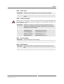
The ">" character in front of a menu item means that a sub-menu is available. An
"x" in front of a menu item means that there is a configuration option which needs to
be activated through a higher configuration option before being accessible.
MEN Mikro Elektronik GmbH
20RC01-00 E4 – 2011-01-31
31
BIOS
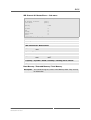
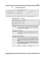
4.3
Standard CMOS Features
Phoenix - AwardBIOS CMOS Setup Utility
Standard CMOS Features
+=====================================================+========================+
|
Date (mm:dd:yy)
Mon, Jan 23 2008
|
Item Help
|
|
Time (hh:mm:ss)
10 : 57 : 22
|------------------------|
|
| Menu Level
>
|
| > IDE Channel 0 Master
[ None]
|
|
| > IDE Channel 0 Slave
[ None]
|
|
|
|
|
|
|
|
|
Base Memory
640K
|
|
|
Extended Memory
2086912K
|
|
|
Total Memory
2087936K
|
|
|
|
|
|
|
|
+=====================================================+========================+
F5: Previous Values
F6: BIOS Default Values
F7: Last Saved Values
Date (mm:dd:yy)
Description
Change the day, month, year and century.
Options
mm
Month
dd
Day
yy
Year
Time (hh:mm:ss)
Description
Change the internal clock.
Options
hh
Hours
mm
Minutes
ss
Seconds
MEN Mikro Elektronik GmbH
20RC01-00 E4 – 2011-01-31
32
BIOS
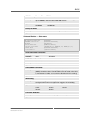
IDE Channel 0/1 Master/Slave — Sub-menu
IDE HDD Auto-Detection
[Press Enter]
IDE Channel 0 Master
Access Mode
[Auto]
[Auto]
Capacity
0 MB
Cylinder
Head
Precomp
Landing Zone
Sector
0
0
0
0
0
IDE HDD Auto-Detection
Description
Auto-detects the HDD's size, head etc. on this channel.
Options
None
IDE Channel 0/1 Master/Slave
Options
None
Manual
Auto
Access Mode
Options
CHS
Large
LBA
Auto
Capacity / Cylinder / Head / Precomp / Landing Zone / Sector
Options
None
Base Memory / Extended Memory / Total Memory
Description
MEN Mikro Elektronik GmbH
20RC01-00 E4 – 2011-01-31
You cannot change any values in the Memory fields. They are only
for information.
33
BIOS
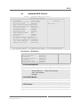
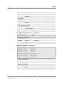
4.4
Advanced BIOS Features
Phoenix - AwardBIOS CMOS Setup Utility
Advanced BIOS Features
+=====================================================+========================+
| > CPU Feature
[Press Enter]
|
Item Help
|
| > Hard Disk Boot Priority
[Press Enter]
|------------------------|
|
CPU L1 & L2 Cache
[Enabled]
| Menu Level
>
|
|
Hyper-Threading Technology[Enabled]
|
|
|
Quick Power On Self Test [Enabled]
|
|
|
First Boot Device
[Hard Disk]
|
|
|
Second Boot Device
[ZIP100]
|
|
|
Third Boot Device
[LS120]
|
|
|
Boot Other Device
[Enabled]
|
|
|
Boot Up NumLock Status
[On]
|
|
|
Security Option
[Setup]
|
|
| x APIC Mode
[Enabled]
|
|
|
MPS Version Control For OS[1.4]
|
|
|
OS Select For DRAM > 64MB [Non-OS2]
|
|
|
HDD S.M.A.R.T Capability [Disabled]
|
|
|
Full Screen LOGO Show
[Disabled]
|
|
|
Summary Screen Show
[Disabled]
|
|
|
|
|
|
|
|
|
|
|
+=====================================================+========================+
F5: Previous Values
F6: BIOS Default Values
F7: Last Saved Values
CPU Feature — Sub-menu
Thermal Management
Limit CPUID MaxVal
C1E Function
CPU C State Capability
On-Demand TCC
Execute Disable Bit
Virtualization Technology
[Thermal Monitor 2]
[Disabled]
[Disabled]
[Disabled]
[Disabled]
[Enabled]
[Enabled]
Thermal Management
Description
Shows the active thermal management.
Options
Thermal Monitor 1
On die throttling
Thermal Monitor 2
Ratio & VID transition
TM1 + TM2 enabled
Disabled
Limit CPUID MaxVal
Description
Set Limit CPUID MaxVal to 3, should be disabled for WinXP
Options
Disabled
Enabled
C1E Function
Description
Enables the Enhanced Halt State for power saving
Options
Disabled
MEN Mikro Elektronik GmbH
20RC01-00 E4 – 2011-01-31
Auto
34
BIOS
CPU C State Capability
Description
User can select the lowest C state supported according to CPU
and MB
Options
Disabled
C2
C4
C6
On-Demand TCC
Description
When enabled, it indicates the clock on to clock off interval ratio.
Options
Disable
50.0%
12.5%
62.5%
25.0%
75.0%
37.5%
87.5%
Execute Disable Bit
Description
When disabled, forces the XD feature flag to always return 0.
Options
Enabled
Disabled
Virtualization Technology
Description
When enabled, a VMM can utilize the addional hardware capabilities provided by Vanderpool Technology. (Not available for
RC1 versions with the Atom Z510 processor.)
Options
Enabled
Disabled
Hard Disk Boot Priority — Sub-menu
1.
2.
3.
2.
USB-HDD0 : Intel Value SSD
USB-HDD1 : Intel Value SSD
USB-HDD2 : SanDisk Cruzer Micro
Bootable Add-in-Cards
Boot priority [Dynamic]
Description
Selects the boot device priority of any hard disk recognized.
Options
Dynamic
New detected devices are added to the end of the
boot-list.
Manual
The chosen setting is saved as long as the HDD
configuration of the system is not changed. (This
setting is advantageous if there is no battery in
the system).
Fixed
The BIOS scans the IDE controller and always
fixes the boot sequence:
1. HDD from 1st controller
2. HDD from 2nd controller
3. USB-HDD devices
MEN Mikro Elektronik GmbH
20RC01-00 E4 – 2011-01-31
35
BIOS
CPU L1 & L2 Cache
Description
Allows to enable or disable the processor cache memory.
You should disable cache only if absolutely necessary, e.g. for testing purposes, since this slows down the system considerably.
Options
Enabled
Disabled
Hyper-Threading Technology
Description
Enabled for Windows® XP and Linux 2.4.x (OS optimized for Hyper
Threading Technology) and Disable for other OS (OS not optimized
for Hyper Threading Technology). (Not available for RC1 versions
with the Atom Z510 processor.)
Options
Enabled
Disabled
Quick Power On Self Test
Description
Allows the system to skip certain tests while booting. This will
decrease the time needed to boot the system.
Options
Enabled
Disabled
First Boot Device / Second Boot Device / Third Boot Device
Description
Selects your boot device priority.
Options
LS120
ZIP100
USB-CDROM
Hard Disk
USB-FDD
Legacy LAN
CDROM
USB-ZIP
Disabled
Boot Other Device
Description
Selects your boot device priority.
Options
Enabled
Disabled
Boot Up NumLock Status
Description
Selects power on state for NumLock.
Options
Off
On
Security Option
Description
Selects whether the password is required every time the system
boots or only when you enter setup.
Options
Setup
MEN Mikro Elektronik GmbH
20RC01-00 E4 – 2011-01-31
System
36
BIOS
APIC Mode
Description
APIC mode extends the number of available IRQs (up to 23 IRQs)
for operating systems which can use this (Windows® XP/2000).
Options
Enabled
MPS Version Control For OS
Description
Selects the multiprocessor specification (MPS) revision.
Options
1.4
1.1
OS Select For DRAM > 64MB
Description
Select OS2 only if you are running an OS/2 operating system with
greater than 64MB of RAM on the system.
Options
Non-OS2
OS2
HDD S.M.A.R.T Capability
Description
Enables the hard disk drive S.M.A.R.T capability. The Self Monitoring Analysis And Reporting technology monitors the hard disk's
condition and allows early prediction and warning of the hard disk
failing.
In order to use S.M.A.R.T you have to enable it and keep the
S.M.A.R.T.-aware hardware monitoring utility running in the background all the time.
Options
Disabled
Enabled
Full Screen LOGO Show
Description
Reserved to select between boot logos.
Options
Disabled
Summary Screen Show
Description
Show summary screen
Options
Enabled
MEN Mikro Elektronik GmbH
20RC01-00 E4 – 2011-01-31
Disabled
37
BIOS
4.5
!
Advanced Chipset Features
You should make changes in this menu only if you have thorough knowledge of
your system! Setting wrong values in this section may cause the system to
malfunction!
Phoenix - AwardBIOS CMOS Setup Utility
Advanced Chipset Features
+=====================================================+========================+
|
DRAM Timing Selectable
[By SPD]
|
Item Help
|
|
System BIOS Cacheable
[Enabled]
|------------------------|
|
Video BIOS Cacheable
[Disabled]
| Menu Level
>>
|
|
|
|
|
|
|
|
** VGA Setting **
|
|
|
On-Chip Frame Buffer Size [8MB]
|
|
|
Boot Type
[VBIOS Default]
|
|
|
LCD Panel Type
[640x480 generic]
|
|
|
Panel Scaling
[Auto]
|
|
|
BIA Control
[VBIOS Default]
|
|
|
TV Feature
Press Enter
|
|
|
|
|
+=====================================================+========================+
F5: Previous Values
F6: BIOS Default Values
F7: Last Saved Values
DRAM Timing Selectable
Description
Sets the method by which the DRAM timing is selected. If By SPD
is selected, the values for the following five items are configured
from the contents of the SPD (Serial Presence Detect) device.
Options
By SPD
System BIOS Cacheable
Description
Selecting Enabled allows caching of the system BIOS ROM at
0xF0000 to 0xFFFFF, resulting in better system performance.
Options
Enabled
Disabled
Video BIOS Cacheable
Description
Selecting Enabled allows caching of the video BIOS ROM at
0xC0000 to 0xCFFF, resulting in better video performance.
Options
Enabled
Disabled
VGA — On-Chip Frame Buffer Size
Description
Controls the pre-allocated memory for frame buffer
Options
1MB
8MB
4 MB
MEN Mikro Elektronik GmbH
20RC01-00 E4 – 2011-01-31
38
BIOS
VGA — Boot Type
Description
Selects the video device that will be activated during POST
Options
VBIOS Default
SDVO
LVDS
VGA — LCD Panel Type
!
Warning: Do not change this setting to anything different than 640x480! While the
internal hardware of the RC1 generally supports several different resolutions, the
unit’s display does not!
Description
Selects the LCD panel used by the internal graphics device by
selecting the appropriate setup item. Some panels are not numbered due to size constraints
Options
640x480 generic
1024x600 TMD 5.61"
800x600 generic
1024x600 Samsung 4.8"
1024x768 generic
1024x768 Samsung 15"
640x480 NEC 8.4 "
1024x768 Sharp 7.2"
800x480 NEC 9"
1280x800 Samsung 15.4
VGA — Panel Scaling
Description
Controls the type of panel scaling
Options
Auto
VGA — BIA Control
Description
Selects BIA control and aggressiveness level through this setup
item
Options
VBIOS Default
MEN Mikro Elektronik GmbH
20RC01-00 E4 – 2011-01-31
39
BIOS
4.6
Integrated Peripherals
Phoenix - AwardBIOS CMOS Setup Utility
Integrated Peripherals
+=====================================================+========================+
| > On-Chip IDE Device
[Press Enter]
|
Item Help
|
| > Onboard Device
[Press Enter]
|------------------------|
| > PCI Express Root Port Func[Press Enter]
| Menu Level
>
|
| > USB Device Setting
[Press Enter]
|
|
|
|
|
|
|
|
+=====================================================+========================+
F5: Previous Values
F6: BIOS Default Values
F7: Last Saved Values
On-Chip IDE Device — Sub-menu
IDE HDD Block Mode
On-Chip Primary PCI IDE
IDE Primary Master PIO
IDE Primary Slave PIO
IDE Primary Master UDMA
IDE Primary Slave UDMA
Delay for HDD (Secs)
[Enabled]
[Enabled]
[Auto]
[Auto]
[Auto]
[Auto]
[0]
IDE HDD Block Mode
Description
If your IDE hard drive supports block mode, select Enabled for
automatic detection of the optimal number of block read/writes
per sector the drive can support.
Options
Enabled
Disabled
On-Chip Primary PCI IDE
Description
The integrated peripheral controller contains an IDE interface
with support for two IDE channels. Select Enabled to activate
each channel.
Options
Enabled
Disabled
IDE Primary Master/Slave PIO
Description
These fields allow your system hard disk controller to work faster.
Rather than have the BIOS issue a series of commands that
transfer to or from the disk drive, PIO (Programmed Input/Output)
allows the BIOS to communicate with the controller and CPU
directly.
The system supports five modes, numbered from 0 to 4, which
primarily differ in timing. When Auto is selected, the BIOS will
select the best available mode.
Options
MEN Mikro Elektronik GmbH
20RC01-00 E4 – 2011-01-31
Auto
Mode 1
Mode 3
Mode 0
Mode 2
Mode 4
40
BIOS
IDE Primary Master/Slave UDMA
Description
These fields allow your system to improve disk I/O throughput to
up to 100MB/s with the Ultra DMA/100 feature.
Options
Auto
Disabled
UDMA66
UDMA100
UDMA33
Delay for HDD
Description
This feature allows users to set a higher delay for HDD detection
Options
0-15 seconds
Onboard Device — Sub-menu
Intel HD Audio Controller
USB Client Controller
SDIO/MMC Controller
Watchdog
Console Redirect
Serial Port Mode
After Boot
Flow Control
[Auto]
[Enabled]
[Enabled/Disabled]
[Disabled]
[COM1/Disabled]
[115200,8,n,1 19200,8,n,1 9600,8,n,1]
[Enabled/Disabled]
[Ignore/Tested]
Intel HD Audio Controller
Description
Enables/disables the audio controller.
Options
Auto
Disabled
USB Client Controller
Description
Enables/disables the USB client controller.
Options
Enabled
Disabled
SDIO/MMC Controller
Description
Enables/disables the Secure Digital I/O (SDIO)/Multimedia Card
(MMC) controller. Note: The MicroSD card slot used in the RC1
is connected via USB, so it cannot be disabled via this setting!
Options
Enabled
Disabled
Watchdog
Description
If the watchdog is active the system will be rebooted after the
configured time when no application triggers the watchdog
Options
Disabled
1 min
2 min
5 min
10 min
15 min
20 min
30 min
Console Redirect
Description
Enables control via terminal program on serial port.
Options
COM1
MEN Mikro Elektronik GmbH
20RC01-00 E4 – 2011-01-31
Disabled
41
BIOS
Serial Port Mode
Description
Selects the serial port settings
Options
115200,8,n,1
19200,8,n,1
9600,8,n,1
After Boot
Description
Console Redirect also active after Boot Up. Only supported by
some OS.
Options
Enabled
Disabled
Flow Control Signals
Description
Enables hardware handshake. Ignore means hardware handshake is disabled.
Options
Ignore
Tested
PCI Express Root Port Func — Sub-menu
PCI Express Port 1
PCI Express Port 2
[Auto]
[Auto]
PCI Express Port 1/2
Description
Controls the activity of the PCI Express ports.
Options
Enabled
Disabled
Auto
USB Device Setting — Sub-menu
USB
USB
USB
USB
USB
1.0 Controller
2.0 Controller
Operation Mode
Keyboard Function
Storage Function
[Enabled]
[Enabled]
[High Speed]
[Enabled]
[Enabled]
***USB Mass Storage Device Boot Setting***
Intel Value SSD 2.00
[Auto Mode]
Intel Value SSD 2.00
[Auto Mode]
SanDisk Cruzer Micro 0.1 [Auto Mode]
USB 1.0 Controller
Description
Enables/disables the Universal Host Controller interface for USB.
Options
Enabled
Disabled
USB 2.0 Controller
Description
Enables/disables the Enhanced Host Controller interface for
USB.
Options
Enabled
MEN Mikro Elektronik GmbH
20RC01-00 E4 – 2011-01-31
Disabled
42
BIOS
USB Operation Mode
Description
Auto-selects USB device operation mode
Options
High Speed
If the USB device is a high speed device, it
operates in high-speed mode. If the USB
device is a full/low-speed device, it operates
in full/low speed mode
Full/Low Speed
All USB devices operate on full/low speed
mode.
USB Keyboard Function
Description
Enables/disables the USB Keyboard Function.
Options
Enabled
USB Storage Function
Description
Enables/disables the legacy support of USB Mass Storage
Options
Enabled
Disabled
Intel Value SSD 2.00/SanDisk Cruzer Micro 0.1
Description
Selects the boot up type for the USB SSD
Options
Auto mode
According to contents of USB mass storage
device
FDD mode
USB mass storage device boots up as floppy
disk
HDD mode
USB mass storage device boots up as hard
disk
MEN Mikro Elektronik GmbH
20RC01-00 E4 – 2011-01-31
43
BIOS
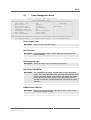
4.7
Power Management Setup
Phoenix - AwardBIOS CMOS Setup Utility
Power Management Setup
+=====================================================+========================+
|
Power-Supply Type
[AT]
|
Item Help
|
|
ACPI Function
[Enabled]
|------------------------|
|
ACPI Suspend Type
[S3(STR)]
| Menu Level
>
|
|
Soft-Off by PWR-BTTN
[Instant-Off]
|
|
|
PWRON After PWR-Fail
[On]
|
|
|
ATX_PWRGD Failure Mode
[Check at Startup]
|
|
| > HPET Feature
[Press Enter]
|
|
| > Intel DTS Feature
[Press Enter]
|
|
|
|
|
+=====================================================+========================+
F5: Previous Values
F6: BIOS Default Values
F7: Last Saved Values
Power-Supply Type
Description
Selects the type of power supply.
Options
AT
ATX
ACPI Function
Description
Enables/disables support of ACPI (Advance Configuration and
Power Interface).
Options
Enabled
ACPI Suspend Type
Description
Selects the ACPI state used for System Suspend.
Options
S3(STR)
Activates "Suspend To RAM" function.
Soft-Off by PWR-BTTN
Description
This field defines the power-off mode when using an ATX power
supply. The Instant-Off mode allows powering off immediately upon
pressing the power button. In the Delay 4 Sec. mode, the system
powers off when the power button is pressed for more than four
seconds or enters the suspend mode when pressed for less than 4
seconds.
Options
Instant-Off
Delay 4 Sec.
PWRON After PWR-Fail
Description
Sets the system power status when power returns to the system
from a power failure situation.
Options
Former-Sts
MEN Mikro Elektronik GmbH
20RC01-00 E4 – 2011-01-31
On
Off
44
BIOS
ATX_PWRGD Failure Mode
Description
Determines the system behaviour in case of a failure at the ATX
power good signal.
Options
Check at start up
Check always
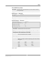
HPET Feature — Sub-menu
HPET Support
[Enabled]
HPET Support
Description
Enables/disables the high-precision event timer in the chipset.
Options
Enabled
Disabled
Intel DTS Feature — Sub-menu
Intel DTS Function
x DTS Active temperature
x Passive Cooling Trip Point
x Passive TC1 Value
x Passive TC2 Value
x Passive TSP Value
Critical Trip Point
[Enabled]
55°C
95°C
2
0
10
POR
Intel DTS Function
Description
Enables/disables Intel DTS Function.
Options
Enabled
Disabled
DTS Active temperature/Passive Cooling Trip Point/Passive TC1
Value/Passive TC2 Value/Passive TSP Value
Description
These values are read-only values as monitored by the system
when the Intel DTS Feature is enabled.
Options
None
Critical Trip Point
Description
This value controls the temperature of the ACPI Critical Trip
Point; i.e., the point at which the operating system will shut down
the system.
Options
POR1
15°C
23°C
31°C
39°C
47°C
55°C
63°C
71°C
79°C
87°C
95°C
103°C
111°C
119°C
127°C
1POR
= 100°C
MEN Mikro Elektronik GmbH
20RC01-00 E4 – 2011-01-31
45
BIOS
4.8
PNP/PCI Configurations
Phoenix - AwardBIOS CMOS Setup Utility
PnP/PCI Configurations
+=====================================================+========================+
|
Init Display First
[Onboard]
|
Item Help
|
|
Reset Configuration Data [Disabled]
|------------------------|
|
| Menu Level
>
|
|
Resources Controlled By
[Auto(ESCD)]
|
|
| x IRQ Resources
[Press Enter]
|
|
|
|
|
|
PCI/VGA Palette Snoop
[Disabled]
|
|
|
PCI Latency Timer(CLK)
[ 32]
|
|
|
|
|
|
** PCI Express relative items **
|
|
|
Maximum Payload Size
[128]
|
|
|
|
|
+=====================================================+========================+
F5: Previous Values
F6: BIOS Default Values
F7: Last Saved Values
Init Display First
Description
Selects which graphics controller the system initializes when the
system boots.
Options
PCI Slot
Onboard
Reset Configuration Data
Description
Select Enabled to reset Extended System Configuration Data
(ESCD) when you exit Setup if you have installed a new add-on and
the system reconfiguration has caused such a serious conflict that
the OS cannot boot. Disabled is the default.
Options
Enabled
Disabled
Resources Controlled By
Description
BIOS can automatically configure all the boot and Plug&Play compatible devices. If you choose Auto, you cannot select IRQ, DMA
and memory base address fields, since BIOS automatically assigns
them.
Options
Auto(ESCD)
Manual
IRQ Resources
Description
MEN Mikro Elektronik GmbH
20RC01-00 E4 – 2011-01-31
When resources are controlled manually, you must assign each
system interrupt a type depending on the type of device using the
interrupt, i.e. either a PCI/ISA Plug&Play device (default) or a Legacy ISA device.
46
BIOS
PCI/VGA Palette Snoop
Description
Some non-standard VGA display cards may not show colors properly. This field allows you to set whether or not MPEG ISA/VESA
VGA cards can work with PCI/VGA. When this field is enabled, a
PCI/VGA can work with an MPEG ISA/VESA VGA card. When this
field is disabled, a PCI/VGA cannot work with an MPEG ISA/VESA
card.
Options
Enabled
Disabled
PCI Latency Timer (CLK)
Description
This BIOS feature controls how long a PCI device can hold the PCI
bus before another takes over. The longer the latency, the longer
the PCI device can retain control of the bus before handing it over to
another PCI device.
Normally, the PCI Latency Timer is set to 32 cycles. This means the
active PCI device has to complete its transactions within 32 clock
cycles or hand it over to the next PCI device.
For better PCI performance, a longer latency should be used, but a
long latency can also reduce performance as the other PCI devices
queuing up may be stalled for too long. The optimum latency time
depends on your system configuration.
Options
Decimal value between 0 and 255
Maximum Payload Size
Description
Sets the maximum TLP payload size for the PCI Express devices.
The unit is byte.
Options
128
MEN Mikro Elektronik GmbH
20RC01-00 E4 – 2011-01-31
47
BIOS
4.9
PC Health Status
Phoenix - AwardBIOS CMOS Setup Utility
PC Health Status
+=====================================================+========================+
|
Current System Temp
41°C
|
Item Help
|
|
Current CPU1 Temperature
38°C
|------------------------|
|
| Menu Level
>
|
|
|
|
|
|
|
|
|
|
+=====================================================+========================+
F5: Previous Values
F6: BIOS Default Values
F7: Last Saved Values
Current System Temp/Current CPU1 Temperature
Description
4.10
These values are read-only values as monitored by the system.
Frequency/Voltage Control
Phoenix - AwardBIOS CMOS Setup Utility
Frequency/Voltage Control
+=====================================================+========================+
|
Spread Spectrum
[Enabled]
|
Item Help
|
|
XPD Clock
[Disabled]
|------------------------|
|
| Menu Level
>
|
|
|
|
|
|
|
+=====================================================+========================+
F5: Previous Values
F6: BIOS Default Values
F7: Last Saved Values
Spread Spectrum
Description
Sets the value of the spread spectrum. If enabled, this setting
improves CE behavior.
Options
Disabled
Enabled
XPD Clock
Description
Enables the clock for the debug connector
Options
Disabled
MEN Mikro Elektronik GmbH
20RC01-00 E4 – 2011-01-31
Enabled
48
BIOS
4.11
Load Fail-Safe Defaults
If this option is selected, a verified factory setup is loaded.
On the first BIOS setup configuration, this loads safe values for setup, which make
the board boot up. This state is achieved again when the board is reprogrammed
with the necessary parameters using the related Flash program.
4.12
Load Optimized Defaults
At the moment this option has the same effect as described for Load Fail-Safe
Defaults.
If required, this option can be used to load optimized values, e.g. for the board to
boot faster. These values have to be defined in the BIOS binary by the BIOS
manufacturer. A special BIOS version is needed for this.
4.13
Set Password
This lets you set a password. Please note that this often leads to problems, since
passwords are easily forgotten.
4.14
Save & Exit Setup
This option saves the settings made and exits setup.
4.15
Exit without Saving
This exits setup without saving any settings.
MEN Mikro Elektronik GmbH
20RC01-00 E4 – 2011-01-31
49
Organization of the System
5
Organization of the System
5.1
Memory Mappings
5.1.1
Processor View of the Memory Map
The memory map is allocated dynamically and may vary depending on the system
configuration.
Table 16. Memory map – processor view
Address Range
0xFDF00000..0xFDF7FFFF
Video controller (VGA-compatible)
0xD8000000..0xDFFFFFFF
Video controller (VGA-compatible)
0xFDFC0000..0xFDFDFFFF
Video controller (VGA-compatible)
0xFDFFF000..0xFDFFFFFF
USB (Universal Serial Bus)-Controller
0xFDFF8000..0xFDFFBFFF
Microsoft UAA bus driver for High Definition
Audio
0xFDB00000..0xFDBFFFFF
PCI standard-PCI-to-PCI-bridge
0xFDE00000..0xFDEFFFFF
PCI standard-PCI-to-PCI-bridge
0xFDBC0000..0xFDBDFFFF
Reserved
0xFDBFC000..0xFDBFFFFF
Reserved
0xFDD00000..0xFDDFFFFF
PCI standard-PCI-to-PCI-bridge
0xFDC00000..0xFDCFFFFF
PCI standard-PCI-to-PCI-bridge
0xFDFFE000..0xFDFFE3FF
Standard extended PCI-to-USB universal host
controller
0xFED00000..0xFED003FF
High precision event timer
0xFED00000..0xFED003FF
System board
0xFFB80000..0xFFBFFFFF
Intel(R) 82802 firmware hub
0xE0000000..0xEFFFFFFF
Motherboard resources
0x0000..0x9FFFF
System board
0xFEC00000..0xFEC00FFF
System board
0xFED13000..0xFED1DFFF
System board
0xFED20000..0xFED8FFFF
System board
0xFEE00000..0xFEE00FFF
System board
0xFFB00000..0xFFB7FFFF
System board
0xFFF00000..0xFFFFFFFF
System board
0xA0000..0xBFFFF
PCI bus
0xA0000..0xBFFFF
VGASave
0xC0000..0xDFFFF
PCI bus
0xE0000..0xEFFFF
PCI bus
0xE0000..0xEFFFF
System board
MEN Mikro Elektronik GmbH
20RC01-00 E4 – 2011-01-31
Function
50
Organization of the System
Address Range
Function
0xF0000..0xFFFFF
PCI bus
0xF0000..0xFFFFF
System board
0x100000..0x1F5DFFFF
System board
0x1F5E0000..0x1F5FFFFF
System board
0x1F600000..0x1F6FFFFF
System board
0x1F700000..0xFEBFFFFF
PCI bus
5.1.2
I/O Memory Map
Table 17. Memory map – I/O
Address Range
0x00000000..0x00000CF7
PCI bus
0x00000000..0x00000CF7
DMA controller
0x00000010..0x0000001F
Motherboard resources
0x00000020..0x00000021
Programmable interrupt controller
0x00000022..0x0000003F
Motherboard resources
0x00000040..0x00000043
System timer
0x00000044..0x0000005F
Motherboard resources
0x00000061..0x00000061
Reserved
0x00000062..0x00000063
Motherboard resources
0x00000065..0x0000006F
Motherboard resources
0x00000070..0x00000073
System CMOS/real time clock
0x00000074..0x0000007F
Motherboard resources
0x00000080..0x00000090
DMA controller
0x00000091..0x00000093
Motherboard resources
0x00000094..0x0000009F
DMA controller
0x000000A0..0x000000A1
Programmable interrupt controller
0x000000A2..0x000000BF
Motherboard resources
0x000000C0..0x000000DF
DMA controller
0x000000E0..0x000000EF
Motherboard resources
0x000000F0..0x000000FF
Numerical coprocessor
0x00000170..0x00000177
Reserved
0x000001CE..0x000001CF
VgaSave
0x000001F0..0x000001F7
Reserved
0x00000274..0x00000277
ISAPnP data read port
0x00000279..0x00000279
ISAPnP data read port
0x000002E8..0x000002EF
VgaSave
0x00000376..0x00000376
Reserved
MEN Mikro Elektronik GmbH
20RC01-00 E4 – 2011-01-31
Function
51
Organization of the System
Address Range
Function
0x000003B0..0x000003BB
VgaSave
0x000003C0..0x000003DF
VgaSave
0x000003F6..0x000003F6
Reserved
0x000004D0..0x000004D1
Motherboard resources
0x00000880..0x0000088F
Motherboard resources
0x00000900..0x000009BF
Motherboard resources
0x00000A79..0x00000A79
ISAPnP data read port
0x00000D00..0x0000FFFF
PCI bus
0x0000D000..0x0000DFFF
PCI standard-PCI-to-PCI-bridge
0x0000E000..0x0000EFFF
PCI standard-PCI-to-PCI-bridge
0x0000EF00..0x0000EF1F
Reserved
0x0000FB00..0x0000FB0F
Standard dual channel PCI-IDE controller
0x0000FC00..0x0000FC1F
Standard PCI-to-USB universal host controller
0x0000FD00..0x0000FD1F
Standard PCI-to-USB universal host controller
0x0000FE00..0x0000FE1F
Standard PCI-to-USB universal host controller
0x0000FF00..0x0000FF07
Video controller (VGA-compatible)
5.2
PCI Devices
Table 18. PCI Devices
Bus
Device
Number
0
0x00
0
Vendor ID
Device ID
0x0
0x8086
0x8100
Host bridge
0x02
0x0
0x8086
0x8108
Display Controller
0
0x1A
0x00
0x8086
0x8118
USB Client Controller
0
0x1B
0x00
0x8086
0x811B
HD Audio Controller
0
0x1C
0x00
0x8086
0x8110
PCI Express Root Port 1
0
0x1C
0x01
0x8086
0x8110
PCI Express Root Port 2
0
0x1D
0x00
0x8086
0x8114
USB UHCI Controller 1
0
0x1D
0x01
0x8086
0x8115
USB UHCI Controller 2
0
0x1D
0x02
0x8086
0x8116
USB UHCI Controller 3
0
0x1D
0x07
0x8086
0x8117
USB EHCI Controller
0
0x1E
0x00
0x8086
0x811C
SDIO/MMC Port 0
0
0x1E
0x01
0x8086
0x811D
SDIO/MMC Port 1
0
0x1E
0x02
0x8086
0x811E
SDIO/MMC Port 2
0
0x1F
0x00
0x8086
0x8119
LPC Controller
0
0x1F
0x01
0x8086
0x811A
Reserved
1
0x00
0x00
0x1A88
0x4D45
Bridge Device [MENFPGA]
MEN Mikro Elektronik GmbH
20RC01-00 E4 – 2011-01-31
Device
Function
Function
52
Organization of the System
5.3
SMBus Devices
Table 19. SMBus devices
Address
Function
0x40
IO expander (power supply states and PCI Express Mini
Card enable/disable)
0x4C
Thermal sensor
0x9A
Board management controller
0xA0
SPD data for system memory
0xAA
CPU board information EEPROM
0xAC
EEPROM for customer specific data
0xAE
RC1 board information EEPROM
0xD2
Clock generator
5.4
Interrupt Mapping
Table 20. Interrupts
Interrupt
IRQ 0
High precision event timer
IRQ 8
High precision event timer
IRQ 9
Microsoft ACPI-conformal system
IRQ 11
Video controller (VGA-compatible)
IRQ 11
USB (Universal Serial Bus) controller
IRQ 13
Numerical coprocessor
IRQ 14
Reserved
IRQ 16
Microsoft UAA bus driver for High Definition Audio
IRQ 16
PCI standard-PCI-to-PCI-bridge
IRQ 16
Standard PCI-to-USB universal host controller
IRQ 17
PCI standard-PCI-to-PCI-bridge
IRQ 17
Standard PCI-to-USB universal host controller
IRQ 18
Standard PCI-to-USB universal host controller
IRQ 19
Standard extended PCI-to-USB universal host controller
MEN Mikro Elektronik GmbH
20RC01-00 E4 – 2011-01-31
Function
53
Maintenance
6
Maintenance
6.1
Cleaning the Display
Please clean the display of the RC1 with a moist, soft cloth. Do not use abrasive
detergents in order to avoid damaging the laminated glass that protects the display.
6.2
!
Fuse Protection
The DC/DC converter inside the RC1’s power supply unit is protected by a fuse.
This fuse is not intended to be exchanged by the customer. Your warranty for
the Power Supply Unit will cease if you exchange the fuse on your own. Please
send your unit to MEN for repair if a fuse blows.
• Current rating:
- 2.5A for a 24V nom. PSU (standard)
- 1A for a 110V nom. PSU
• Type: fast
• Size: 4.5 x 12.1
• MEN part number: 5675-0010 (2.5A), 5675-0006 (1A)
MEN Mikro Elektronik GmbH
20RC01-00 E4 – 2011-01-31
54
Appendix
7
Appendix
7.1
Pin Assignment of PCI Express Mini Card Connector
The RC1 supports the PCI Express Mini Card standard as a means of adding
wireless functionality to the unit. A PCI Express Mini Card is a small form factor
optimized for mobile computing platforms and a card-system interconnection
optimized for communication applications.
Internally, the RC1 is equipped with a 52-pin standard PCI Express Mini Card
connector and a slot for an optional SIM card. The following signals are supported:
Table 21. Pin assignment of 52-pin PCI Express Mini Card connector
Pin
1
51
MEN Mikro Elektronik GmbH
20RC01-00 E4 – 2011-01-31
2
52
Signal
Direction
Function
1
WAKE#
out
not supported
2
+3.3Vaux
out
Power
3
COEX1
4
GND
5
COEX2
6
1.5V
out
Power
7
CLKREQ#
out
Reference clock request signal
8
UIM_PWR
out
SIM card ower
9
GND
-
Power
10
UIM_DATA
in/out
SIM card data
11
REFCLK-
in
PCI Express differential reference clock
12
UIM_CLK
in
SIM card clock
13
REFCLK+
in
PCI Express differential reference clock
14
UIM_RST
in
SIM card reset
15
GND
-
Power
16
UIM_VPP
not supported
17
Reserved
not supported
18
GND
19
Reserved
not supported
20
W_DISABLE
not supported
21
GND
-
Power
22
PERST#
in
Reset for the Mini Card
23
PERn0
out
PCI Express data receive line
24
+3.3Vaux
out
Power
25
PERp0
out
PCI Express data receive line
26
GND
-
Power
not supported
-
Power
not supported
-
Power
55
Appendix
Pin
7.2
Signal
Direction
Function
27
GND
-
Power
28
+1.5V
out
Power
29
GND
-
Power
30
SMB_CLK
out
not supported
31
PETn0
in
PCI Express data transmit line
32
SMB_DATA
in/out
not supported
33
PETp0
in
PCI Express data transmit line
34
GND
-
Power
35
GND
-
Power
36
USB_D-
in/out
USB line
37
Reserved
38
USB_D+
in/out
USB line
39
+3.3Vaux
out
Power
40
GND
-
Power
41
+3.3Vaux
out
Power
42
LED_WWAN#
43
GND
44
LED_WLAN#
not supported
45
Reserved
not supported
46
LED_WPAN#
not supported
47
Reserved
not supported
48
+1.5V
49
Reserved
50
GND
51
Reserved
52
+3.3Vaux
not supported
not supported
-
out
Power
Power
not supported
-
Power
not supported
out
Power
Literature and Web Resources
• RC1 data sheet with up-to-date information and documentation:
www.men.de/products/06RC01-.html
7.2.1
PCI Express Mini Card
• PCI Express Mini Card Electromechanical Specification
Revision 1.2; October 26, 2007
PCI Special Interest Group
www.pcisig.com
MEN Mikro Elektronik GmbH
20RC01-00 E4 – 2011-01-31
56
Appendix
7.3
Finding out the Board’s Article Number, Revision and
Serial Number
MEN user documentation may describe several different models and/or hardware
revisions of the RC1. You can find information on the article number, the board
revision and the serial number on two labels attached to the board.
• Article number: Gives the board’s family and model. This is also MEN’s ordering number. To be complete it must have 9 characters.
• Revision number: Gives the hardware revision of the board.
• Serial number: Unique identification assigned during production.
If you need support, you should communicate these numbers to MEN.
Figure 5. Label giving the product’s article number, revision and serial number
Complete article number
Article No.:
06RC01-00
Serial No.:
000000
Rev. 00.00.00
Serial number
Revision number
MEN Mikro Elektronik GmbH
20RC01-00 E4 – 2011-01-31
57