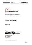
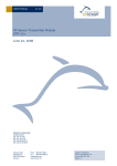
1
Universal 1-channel switching receiver
EnOcean Easyfit RCM 250
User Manual V1.14
May 2007
Revision History
The following major modifications and improvements have been made to the initial version of
the document (User Manual V1.0):
Version Subject (major changes since last version)
V1.1
Relay output switching capabilities added (chapter 1.5)
V1.11
Power dissipation added
V1.12
V1.13
V1.14
Relay switching capability corrected
Declaration of conformity added
Editorial changes
Published by EnOcean GmbH, Kolpingring 18a, 82041 Oberhaching, Germany
www.enocean.com, [email protected], phone ++49 (89) 6734 6890
© EnOcean GmbH, All Rights Reserved
Important!
This information describes the type of component and shall not be considered as assured characteristics. No
responsibility is assumed for possible omissions or inaccuracies. Circuitry and specifications are subject to change
without notice. For the latest product specifications, refer to the EnOcean website: http://www.enocean.com.
As far as patents or other rights of third parties are concerned, liability is only assumed for modules, not for the
described applications, processes and circuits.
EnOcean does not assume responsibility for use of modules described and limits its liability to the replacement of
modules determined to be defective due to workmanship. Devices or systems containing RF components must meet
the essential requirements of the local legal authorities. The approval requirements described in this document are of
best knowledge without any warranty.
The modules must not be used in any relation with equipment that supports, directly or indirectly, human health or life
or with applications that can result in danger for people, animals or real value.
Components of the modules are considered and should be disposed of as hazardous waste. Local government
regulations are to be observed.
Packing: Please use the recycling operators known to you. By agreement we will take packing material back if it is
sorted. You must bear the costs of transport. For packing material that is returned to us unsorted or that we are not
obliged to accept, we shall have to invoice you for any costs incurred.
©EnOcean GmbH, A. Anders
Page 2 of 17
RCM 250 User Manual V1.14
Table of Contents
1. GENERAL DESCRIPTION________________________________________________________________ 4
1.1 Basic Functionalities ________________________________________________________________ 4
1.2 Typical Applications _________________________________________________________________ 4
1.3 Features Overview __________________________________________________________________ 5
1.4 Physical Outline Dimensions _______________________________________________________ 6
1.5 Relay output switching capabilities ________________________________________________ 8
1.6 Terminal Block Description _________________________________________________________ 9
1.7 Environmental Conditions __________________________________________________________ 9
1.8 Ordering Information _______________________________________________________________ 9
2. FUNCTIONAL DESCRIPTION __________________________________________________________ 10
2.1 Block Diagram ______________________________________________________________________ 10
2.2 Connector Description _____________________________________________________________ 10
2.3 Operating Mode ____________________________________________________________________ 11
2.4 Learning of Radio Transmitters ___________________________________________________ 11
2.5 Selective Deleting __________________________________________________________________ 12
2.6 Clear All_____________________________________________________________________________ 12
3. APPLICATIONS INFORMATION _______________________________________________________ 13
3.1 Installation _________________________________________________________________________ 13
3.2 Mounting RCM 250 Near To Metallic Objects _____________________________________ 14
3.3 Transmission Range _______________________________________________________________ 14
3.4 CE Approval Requirements ________________________________________________________ 15
3.5 Product Safety______________________________________________________________________ 16
3.6 Field Intensity Meter EPM 100 ____________________________________________________ 16
4. DECLARATION OF CONFORMITY ______________________________________________________ 17
©EnOcean GmbH, A. Anders
Page 3 of 17
RCM 250 User Manual V1.14
1. GENERAL DESCRIPTION
The 1-channel switching receiver RCM 250 is controlled by radio signals from EnOcean
transmitters and serves to switch various electronic loads such as incandescent lamps, highvoltage halogen lamps, electronic ballast and inductive loads. Each transmitter can
simultaneously control an unlimited number of receivers. Each transmitter has its own fixed
address and has to be assigned to the RCM receiver.
1.1 Basic Functionalities
Each receiver can be assigned, either a maximum of 30 EnOcean PTM radio switches, or up to
2 EnOcean STM 250 radio window contacts. Learning of mixed PTM and STM transmitters is
not possible. The memory of the receiver is empty when delivered. By assigning the first
transmitter the operating mode is defined. The operating mode can only be changed after
deleting all learned transmitters with the CLR button.
a) Mode ROCKER SWITCH: Each assigned PTM transmitter can be used to change the
switching state of the receiver. It is possible to switch ON (button I) with one switch
and OFF (button O) with another switch. When learning a radio switch only the
rocker which has been operated is assigned to the receiver.
b) Mode WINDOW CONTACT: If at least one of the assigned STM 250 window
contacts is open the switching state of the receiver is ON. If both contacts are
closed the state is OFF. The radio window contacts are transmitting a life signal
approx. every 15min. 60 min after reception of the last life signal the receiver
considers this contact to be closed.
Figure 1: 1-channel switching receiver RCM250
1.2 Typical Applications
•
Building installation
•
Industrial automation
•
Consumer Electronics
©EnOcean GmbH, A. Anders
Page 4 of 17
RCM 250 User Manual V1.14
The RCM switching receiver is part of a powerful RF system solution from EnOcean for
operation and control applications. Because the RF transmitters are self-powered (no
batteries), maintenance-free RF systems can be implemented.
The RCM switching receiver operates together with the following further EnOcean components:
PTM (batteryless radio switches), STM 250 (batteryless radio window contact), CTM (remote
control) and TCM (bi-directional IT interface)
1.3 Features Overview
Power Supply: ......................................................................................230 VAC, 50 Hz
Power Dissipation: ................................................................................ 1250mW max.
Relay Output: ................................................ Maximum Load: 1100VA resistive (cosφ=1)
400W tungsten (incandescent lamp), 360W ballast with cosφ=0.4-0.6 (fluorescent lamp)
No. of Relay switching operations: ............................................ 40.000 actuations min.
Radio Frequency: ................................................... 868.3 MHz (stabilized by crystal PLL)
Antenna:...................................................................................... internal whip antenna
Channel Bandwidth / Sensitivity: ..................................................... 280 kHz / -95 dBm
Control Inputs: ....... 2 pushbuttons LRN (set receiver into learning mode) and CLR (clear all)
Learning Mode Indication: ............................ acoustic feedback (switching noise of relais)
Number of RF transmitters learnable: .........up to 30 switches or up to 2 magnet contacts
Note: either PTMs or either STM250s can be learned, not mixed (for priority reasons)
Figure 2: RCM 250 housing
©EnOcean GmbH, A. Anders
Page 5 of 17
RCM 250 User Manual V1.14
1.4 Physical Outline Dimensions
Dimensions of housing: ............................................................. 47.4 x 34.6 x 28.8 mm
Tolerance values of the following 3 outline drawings: ............................... +/- 0.2 mm
Total depth of both holes from
box top to pushbutton: 1.0 mm
Travel of pushbutton: 0.5 to 1.0
mm
Figure 3: RCM 250 side view
Figure 4: RCM 250 front view
©EnOcean GmbH, A. Anders
Page 6 of 17
RCM 250 User Manual V1.14
Figure 5: RCM 250 top view
©EnOcean GmbH, A. Anders
Page 7 of 17
RCM 250 User Manual V1.14
1.5 Relay output switching capabilities
Kind of load
Incandescent lamp 230V AC
Gas discharge lamps / HQL-HQI / not
compensated*
Gas discharge lamps / HQL-HQI /
compensated*
EVG Dynamic / dimmer*
Halogen lamp 230V AC
Fluorescent lamp
230V AC
Electrical life
4 x 100W
20.000 (according to EN60669)
100W
20.000
80W (14µF)
20.000
4 x 18W
3 x 36W
2 x 58W
150W
25.000
20.000
20 x18W
10 x 36W
6 x 58W
4 x 18W
3 x 36W
2 x 58W (2x7µF)
4 x 18W
3 x 36W
2 x 58W
6 x 18W
4 x 36W
3 x 58W
25.000
25.000
25.000
20.000
20.000
20.000
20.000
20.000
20.000
20.000
20.000
20.000
5A
Min. 50.000
Max. capacitance at 230V AC
14 µF
Max. inrush current for max. 20ms at
230V AC
40 A
Min. 5.000 (according to
EN60669)
see above loads
with conventional
ballasts
Fluorescent lamp
230V AC
with electronic
ballasts
Resistive load
230V AC
Not
compensated
cosϕ 0,4 – 0,6
Compensated
with capacitance
in parallel
Compensated
fluorescent
DUO-circuit
Siemens /
Osram
EVG
Maximum Load
cosϕ=1
©EnOcean GmbH, A. Anders
Page 8 of 17
RCM 250 User Manual V1.14
1.6 Terminal Block Description
Terminal Block: .................................................... 4 pole, terminal screw with wire guard
Rated torque/ screw size: ..................................................................... 0,4 Nm / M2,6
Max. rated cross section - Single wire (solid): ............................................... 1.5 mm2
Max. rated cross section - Stranded wire (flex.): ........................................... 1.0 mm2
Max. rated cross section - Stranded wire with ferrules: ................................0.75 mm2
Figure 6: RCM 250 terminal block
1.7 Environmental Conditions
Operating Temperature:..................................................................... -10 up to +45 °C
Storage Temperature: ........................................................................ -25 up to +80 °C
Humidity:...................................................................... 0 % to 95 % r.h., no condensing
1.8 Ordering Information
Type
EnOcean Ordering Code
Remarks
RCM 250
H5002-B250
230 VAC / 50Hz
©EnOcean GmbH, A. Anders
Page 9 of 17
RCM 250 User Manual V1.14
2. FUNCTIONAL DESCRIPTION
2.1 Block Diagram
Figure 7: Block diagram of RCM 250
2.2 Connector Description
Symbol
↓
Function
Load
Operational characteristics
Relays output switched to Hot
L
Hot
Power Supply 230 VAC, 50 Hz
N
Neutral
Power Supply 230 VAC, 50 Hz
N
Neutral
Internally coupled to second N connector
©EnOcean GmbH, A. Anders
Page 10 of 17
RCM 250 User Manual V1.14
2.3 Operating Mode
Each RCM 250 can operate as either a Push Button Switch receiver (by LEARNING EnOcean
PTM 250 Switches) or a Magnet Contact Receiver (by LEARNING EnOcean STM 250 magnet
contacts), but not a mix of devices. The RCM 250 can LEARN either a maximum of 30 EnOcean
PTM 250’s or up to 2 EnOcean STM 250s. The memory of the receiver is empty when
delivered. By assigning the first transmitter the operating mode (push button switch or
magnet contact) is defined. The operating mode can only be changed after deleting all learned
transmitters with the CLR button.
a) Mode ROCKER SWITCH: Each assigned transmitter can be used to change the switching
state of the receiver. It is possible to switch ON (button I) with one switch and OFF (button O)
with another switch. When learning a radio switch with 2-rockers, only the rocker which has
been pressed is learned by the receiver.
Initialization: After Power-up and Learning Phase the relays output is open (“off”). At
least one of the learned radio switches have to be operated to switch the output.
b) Mode WINDOW CONTACT: If at least one of the assigned window contacts is open the
switching state of the receiver is ON. If both contacts are closed the state is OFF.
Time Out: The radio window contacts transmit a ‘supervisory signal’ typically every 15
min (5…30 min). The receiver considers this contact to be closed if there has been no
life signal for more than 60 (± 10%) minutes. Some possible causes for this fail
function: The energy store of the window contact is empty, the radio channel is
disturbed, the window contact has been removed, or the contact is broken.
Initialization: After Power-up and Learning Phase the module output OUT_0 is
inactive (“off”). At least one of the learned magnet contacts have to be opened to
release the output immediately (before first incoming presence signal).
2.4 Learning of Radio Transmitters
1.) For programming the RCM255 must be connected to power. The programming is
retained when power is disconnected. To prevent LEARNING unintentional switches,
when in learn mode, the receiver sensitivity is reduced to approximately 5 meters from
the switch.
2.) Operating the LRN or CLR pushbutton should be done by pushing a non-metallic
insulated probe (e.g. ballpoint pen) carefully through the small hole in the housing onto
the pushbutton behind.
3.) Press the button LRN and hold it down. After 0.3 s programming mode becomes active
confirmed by 1 second cyclic switching of the output relays (“Toggling”): A light
connected to the power output will be switched on and off every second. In quiet
environments the toggling of the relay can be heard.
4.) Transmitters can now be assigned: By pressing one of the rockers of a PTM radio switch
or by pressing the learn button inside the back cover of the STM250 magnet contact,
the transmitter is assigned to the switching receiver, and the relay stops toggling for
©EnOcean GmbH, A. Anders
Page 11 of 17
RCM 250 User Manual V1.14
about 4 seconds. The relay status confirms that the transmitter has been saved
(contact 4s on) or an already learned transmitter is deleted (contact 4s off).
5.) As soon as the toggling of the relays continues, another transmitter can be assigned or
deleted. If the memory is full (30 EnOcean PTM 250 radio switches or 2 EnOcean STM
250 radio window contacts) the receiver goes into operating mode during an attempt to
enter a further transmitter. In this case at least one ID has to be deleted before
entering a new transmitter.
6.) Programming mode is left by re-pressing the LRN button, or after 30 seconds of no
activity the receiver exits programming mode automatically.
2.5 Selective Deleting
A transmitter that has been assigned can be selectively deleted. The programming mode is
activated by pressing the LRN button. Then actuate the rocker or learn button of a previously
learned transmitter, it is now unlearned. Programming mode is left manually by repressing
the LRN button.
2.6 Clear All
If the CLR key is pressed and held for approx. 2 seconds the memory is deleted completely
(condition upon delivery). Then the switching receiver changes to programming mode which is
signaled by the toggling output relays. Programming mode is left manually by pressing the
LRN button.
©EnOcean GmbH, A. Anders
Page 12 of 17
RCM 250 User Manual V1.14
3. APPLICATIONS INFORMATION
3.1 Installation
1.)
2.)
3.)
4.)
5.)
WARNING: To avoid fire, shock, or death: TURN OFF POWER at circuit breaker or
fuse and test that power is off before wiring!
For in-wall mounting an outlet box of 40mm minimum depth must be used. For best
performance do not mount the receivers close to the floor or near to wall niches.
Prepare wires: Make sure that the ends of the wires from the LINE and the LOAD
are straight (cut if necessary). Remove about 7mm of insulation from each wire.
Connect wires per EXAMPLE CIRCUIT as shown in figure 6. The both N clamps are
coupled internally. Use an insolated electrician screw driver with suited tip size.
Installation may now be completed by carefully positioning all wires and stowing the
receiver box. Restore power.
Figure 8: RCM 250 Example Circuit
The integrated ¼-wave whip antenna enables a very compact receiver unit with good radio
reception characteristics. For good receiver performance take attention to the factors
restricting transmission range mentioned in the next both chapters.
Please note that the best range can be received by facing EnOcean transmitters to the
RCM 250 receiver casement top position (see antenna marking on cap). This is a result of
the internal antenna position that can be seen in the following picture:
Far end of
the whip
antenna
Figure 9: Internal position of the RCM 250 whip antenna
©EnOcean GmbH, A. Anders
Page 13 of 17
RCM 250 User Manual V1.14
3.2 Mounting RCM 250 Near To Metallic Objects
For range performance a minimum distance of 1 cm, better 2 cm, should be given
from the whole length of the antenna to any conductive objects. Mainly the far end
of the whip should be mounted as far away as possible from all metal parts.
The internal position of the antenna is shown in Figure 9.
Please note that large metallic parts or conductive objects in the transmission direction causes
shading of the radio waves that could result in range reduction. Using a suited placed repeater
is a prospective remedial measure.
Do not mount the receiver into an enclosed metal housing.
3.3 Transmission Range
Since the radio signals are electromagnetic waves, the signal is attenuated on the way from
the transmitter to the receiver. This means that the field intensity diminishes as the distance
between the transmitter and the receiver increases, and radio range is restricted. Obstacles
between devices can also reduce the range.
In practice, this means that the materials used in the building play an important role when an
assessment of the radio range is made. Some standard values for helping in assessing the
environment:
•
•
•
•
•
Line-of-sight connections: Typically 30m range in corridors, up to 100m in halls
Plasterboard walls / dry wood: Typically 30m range, through max. 5 walls
Brick walls / aerated concrete: Typically 20m range, through max. 3 walls
Ferroconcrete walls / ceilings: Typically 10m range, through max. 1 ceiling
Fire-safety walls, elevator shafts, staircases and supply areas should be
considered as screening.
Other factors restricting transmission range:
•
Switch mounted on metal surfaces (up to 30% loss of transmission range)
•
Hollow lightweight walls filled with insulating wool on metal foil
•
False ceilings with panels of metal or carbon fiber
•
Lead glass or glass with metal coating, steel furniture
•
Mounting transmitter or receiver on the floor, or close to the floor, or at
wall niches
•
Humidity in materials
•
Devices transmitting RF signals such as computers, audio and video
equipment, or electronic gear controls for lamps. A minimum distance of
0.5m should be kept
The angle at which the transmitted signal hits the wall is very important. The effective wall
thickness – and with it the signal attenuation – varies according to this angle. Signals should
be transmitted as directly as possible through the wall. Wall niches should be avoided.
©EnOcean GmbH, A. Anders
Page 14 of 17
RCM 250 User Manual V1.14
Figures 10 and 11: Obstacles reducing the transmission range
3.4 CE Approval Requirements
The devices bear the EC conformity marking CE and conform to the R&TTE EU-directive on
radio equipment. The assembly conforms to the European and national requirements of
electromagnetic compatibility. The conformity has been proven and the corresponding
documentation has been deposited at EnOcean. The EnOcean 868 MHz radio devices can
be operated without notification and free of charge in the area of the European
Union, in Switzerland, in Croatia, in Cyprus, in Czech, in Estonia, in Hungary, in
Latvia, in Lithuania, in Malta, in Poland, in Romania and in Slovenia. The following
provisos apply:
•
EnOcean RF devices must not be modified or used outside their specification
limits.
•
EnOcean RF devices may only be used to transfer digital or digitized data. Analog
speech and/or music are not permitted.
•
The final product incorporating EnOcean RF devices must itself meet the essential
requirement of the R&TTE Directive and a CE marking must be affixed on the final
product and on the sales packaging each. Operating instructions containing a
Declaration of Conformity has to be attached.
•
If transmitters are used according to the regulations of the 868.3 MHz band, a
so-called “Duty Cycle” of 1% per hour for each transmitter must not be
exceeded. Permanent transmitters are not allowed. For conventional applications,
it must be ensured that
a) the PTM radio device is not operated more than 6000 times
within one hour (one operation: energy bow is pressed and
released). Within this calculation, the extraordinary short telegram
©EnOcean GmbH, A. Anders
Page 15 of 17
RCM 250 User Manual V1.14
length is considered including three subtelegrams (see Chapter
2.3.3). Also a tolerance of 5% in the telegram length is included.
b) the STM 250 reed contact is not operated more than 13.000
times per hour (e.g. window opened or window closed). For this
calculation the extraordinary short telegram length is considered
including all subtelegrams (see Chapter 2.3.3). Also a tolerance of 5%
in telegram length is included.
3.5 Product Safety
This device complies with EN 60669. The conformity has been proven by a notified body.
3.6 Field Intensity Meter EPM 100
The EPM100 is a mobile field-intensity meter that helps the engineer to find the best
installation positions for sensor and receiver. It can also be used to check disturbances in links
to already installed equipment.
The EPM100 displays the field intensity of received radio telegrams and interfering radio
signals in the 868MHz range.
The simplest procedure for determining
the best installation positions for the
radio sensor/receiver:
•
Person 1 operates the radio
sensor and generates pushbutton
radio telegrams.
•
Person 2 checks the received field
intensity on the meter display to
find
the
optimal
installation
position.
Figure 12: EPM 100 helps to qualify installation positions
©EnOcean GmbH, A. Anders
Page 16 of 17
RCM 250 User Manual V1.14
4. DECLARATION OF CONFORMITY
©EnOcean GmbH, A. Anders
Page 17 of 17
RCM 250 User Manual V1.14