1
White Wires (2): The two white wires are the output for the turn indicators.
One is to be connected to the right positive side of the turn indicator and
the other is for the left. Both have positive outputs from a relay and both
are isolated so they will not affect turn indicator operation.
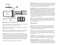
Wire Diagram:
Antenna
LED
RED: System Power
Encore
9 Pin
Learn Button
Blue: Horn Output
Yellow: 12 Volt ACC.
Violet: Kill OUTPUT
Violet: Kill INPUT
White: Rt. Parking Light
Blue/Wht: Horn Input
White: Lt. Parking Light
M1 Two Way
Motorcycle Alarm
3 Pin
2 Pin
Black: System Ground
Locking Tab
3 Pin Connector
Radar Sensor
Siren
2 Pin Connector
Black
Red
Violet
Blue/Wht
Blue
Violet
Yellow
White
White
Connector Front View
Blue / White: This is the input for the horn of the motorcycle. It will allow
you to change the polarity of the horn output. If the motorcycles horn is
triggered by a negative or ground signal, connect this wire to ground. If the
horn has a positive trigger, this wire should be connected to a positive
power source or the red wire of this harness. Please check the horn when
the key is ON and determine if the trigger of the horn is positive or negative.
Once determined turn the key to the OFF position and insure the trigger is
correct. This wire is attached to the common post of a horn relay and will
be open when the horn is not used.
Blue: This is the horn output and will deliver the output polarity based on
the connection to the Blue / white wire above. Please install the siren as
most horn wires are accessible from the outside of the motorcycle and can
easily be disconnected.
Main wire Harness: 9 – Pin Main Harness
Other Connections:
Red: Main unit Power, + 12 Volt. Please connect this wire to constant 12
volt Power at the battery or any stable power source.
Black: Ground (-). Connect this wire to any stable ground or the negative
battery terminal of the motorcycle.
Yellow: This wire should be connected to 12 Volt Ignition. This wire should
have power when the Ignition Key is in the ON or RUN position only.
Violet (2): These wires are the starter or ignition cutoff. They are a relay
input and output. The starter wire or Ignition wire of the motorcycle should
be confirmed and then cut. Both sides of the cut wire should go to either
violet wires. One is the input and the other the output. Either wire can be
used but both need to be connected to complete the circuit. This circuit is
normally closed and will disconnect when the system has been triggered.
Please use caution if interrupting the ignition of the vehicle.
Siren wires: The siren plugs into the two pin connector dedicated for the
siren output. Please secure the siren in a good place facing down and
attach with two screws. This siren has double sided tape on the back but
screws should be used to secure it in place.
Antenna: The antenna should be mounted away from surrounding metal in
an area that is open to allow for the greatest range. It can be placed
beneath fairings or in any area including the handle bars, tail, side covers or
under the seat.
LED Indicator: The LED should be mounted in an area where it can be seen
by the rider as well as any unwanted intruder. This will act as a visual
deterrent and will give the rider notification of the status of the system.
Microwave or Radar Sensor: The Radar sensor is designed to detect
movement above and around the motorcycle. It connects to the three pin
plug on the main unit. This sensor will penetrate all surfaces except metal.
It should be mounted in the middle of the motorcycle facing UP and can be