Download Electronic Motor-Position Sensor Evaluation Unit User`s Manual
Transcript
Mountain Engineering II, Inc. Electronic Motor-Position Sensor Evaluation Unit User’s Manual Mountain Engineering II, Inc. 1233 Sherman Drive Longmont, CO 80501-6133 303 651-0277 • Fax: 303 651-6371 www.mountainengineering.com Table of Contents Getting Started . . . . . . . . . . . . . . . . . . . . . . . . . . . . . . . . . . . . . . . . . . . . . . . . . . . . . . . . . . . . . 2 Packing List . . . . . . . . . . . . . . . . . . . . . . . . . . . . . . . . . . . . . . . . . . . . . . . . . . . . . . . . . 2 Setting Up the Hardware . . . . . . . . . . . . . . . . . . . . . . . . . . . . . . . . . . . . . . . . . . . . . . . 2 Setting up HyperTerminal . . . . . . . . . . . . . . . . . . . . . . . . . . . . . . . . . . . . . . . . . . . . . . 3 Powering Up the EPS Board . . . . . . . . . . . . . . . . . . . . . . . . . . . . . . . . . . . . . . . . . . . . 4 Operating the EPS Console . . . . . . . . . . . . . . . . . . . . . . . . . . . . . . . . . . . . . . . . . . . . . . . . . . . 5 Startup . . . . . . . . . . . . . . . . . . . . . . . . . . . . . . . . . . . . . . . . . . . . . . . . . . . . . . . . . . . . . 5 Console Menu . . . . . . . . . . . . . . . . . . . . . . . . . . . . . . . . . . . . . . . . . . . . . . . . . . . . . . . 5 Position Display Command . . . . . . . . . . . . . . . . . . . . . . . . . . . . . . . . . . . . . . . . . . . . . 6 Position Servo . . . . . . . . . . . . . . . . . . . . . . . . . . . . . . . . . . . . . . . . . . . . . . . . . . . . . . . 6 Speed Servo . . . . . . . . . . . . . . . . . . . . . . . . . . . . . . . . . . . . . . . . . . . . . . . . . . . . . . . . . 7 Principles of EPS Operation . . . . . . . . . . . . . . . . . . . . . . . . . . . . . . . . . . . . . . . . . . . . . . . . . . 8 Impedance Saliency . . . . . . . . . . . . . . . . . . . . . . . . . . . . . . . . . . . . . . . . . . . . . . . . . . . 8 Back EMF . . . . . . . . . . . . . . . . . . . . . . . . . . . . . . . . . . . . . . . . . . . . . . . . . . . . . . . . . . 8 Trickle Current . . . . . . . . . . . . . . . . . . . . . . . . . . . . . . . . . . . . . . . . . . . . . . . . . . . . . . . 9 Initialization . . . . . . . . . . . . . . . . . . . . . . . . . . . . . . . . . . . . . . . . . . . . . . . . . . . . . . . . . 9 Adapting EPS to Your Application . . . . . . . . . . . . . . . . . . . . . . . . . . . . . . . . . . . . . . . . . . . . 10 1 Getting Started Packing List The Electronic Position Sensing evaluation unit consists of the following components: C Motor with attached Electronic Position Sensor (EPS) board C RS-232 cable, consisting of a ribbon cable with a female 9-pin D-sub connector on one end and a 10-pin, dual row socket on the other end. C Power cable, consisting of a pair of wires with a nylon connector on one end, and no connector on the other end. Setting Up the Hardware C Wire the free wire ends of the power cable to a 12 volt power supply. The power supply must tolerate load variations from essentially zero current up to three amperes. The red wire should connect to +12V and the black wire to the return (ground). Do not turn on the 12V power yet, until all the cables are hooked up and the terminal is ready. Warning: reversing the power wires or connecting to incorrect voltage may cause damage to the EPS board. C Plug the power cable connector into the two-pin connector J3 on the EPS board. C Plug the D-sub connector on the RS-232 cable into an RS-232 terminal or a computer to be used as a terminal. The D-sub connector was selected to be compatible with the standard 9-pin PC serial port, and should usually be able to plug in directly to a commodity PC. The PC or terminal will be used as a control console to run the EPS board. C Plug the other end of the RS-232 cable into the header J4 on the EPS board. This is the 10-pin dual-row header which is positioned diagonally on one corner of the board. The connector is keyed to prevent misplugging. C The motor rotor must be able to turn freely. Since the motor shaft extends above and below the motor body, it may be touching the surface that the unit is sitting on. Be sure the motor is not being supported by sitting on the rotor, since that would cause the motor body to spin instead of the shaft. C Also be aware that motor torque can cause the motor body to react by rotating in the opposite direction from the rotor. Take care that the motor can’t “jump” or “walk” itself off a table or into some other kind of trouble. 2 Setting up HyperTerminal If you are using a Microsoft Windows PC as a console terminal, it will usually already be loaded with HyperTerminal software. HyperTerminal was developed for Microsoft by Hilgraeve, Inc. and is installed by default along with most versions of Windows starting with Windows 95. If your PC does not have HyperTerminal, it should be available on your Windows installation disks, or can be downloaded from www.hilgraeve.com. The EPS board console makes no special demands on the console terminal. It uses simple ASCII text only, with no escape sequences or formatting characters. Any other ASCII terminal software should work satisfactorily, as long as it can be set up for the required baud rates. C Start HyperTerminal from the Start menu, Programs, Accessories, Communications, HyperTerminal. C HyperTerminal will display its splash screen, then show the Connection Description dialog box. It prompts you to enter a name to identify the setup configuration. Type any desired name (such as “EPS Console”) and click OK. C The Connect To box will come up next. Use the Connect using drop-down list at the bottom of the box to select the comm port you will use. Usually this will be COM1 (in some versions of HyperTerminal it appears as Direct to Com 1). Don’t select a modem or TCP/IP connection, we will be connecting directly from the comm port. C When you have selected the comm port, the other options in the Connect To box will be disabled (grayed out). Click OK. C Now the COM1 Properties box will appear. In this box, select: C Bits per second: 57600 C Data bits: 8 C Parity: None C Stop bits: 1 C Flow control: None and then click OK. C HyperTerminal should now be configured correctly. The main HyperTerminal screen will be showing, which will initially be mostly blank with a status bar across the bottom, as shown in Figure 1. C When the HyperTerminal window is active, any ASCII keys you press will be transmitted on the RS-232 port. Any ASCII characters received from the EPS board will be displayed in the HyperTerminal window. C You can save the setup you just did by clicking on the File menu and selecting Save or Save As. The saved setup should appear in the Programs menu inside the Accessories / Communications / Hyperterminal folder. The setup (or a shortcut to it) can also be copied to your Windows desktop for convenient access. 3 Figure 1. Initial HyperTerminal screen Powering Up the EPS Board Now that the hardware and the terminal are all set up, it’s time to start up the EPS board. C Turn on the 12 volt power supply. C The green LED on the EPS board should begin to blink. An even pattern of about 50% duty cycle indicates that the console is hooked up correctly and the EPS firmware has started normally. A pattern of double-blinks means that the firmware does not detect valid RS-232 signal levels from a console terminal. In this case, something is wrong with the RS-232 cable hookup or the terminal setup. C When the EPS firmware starts up, the console terminal should display a reset and signon message. C After the signon message, the EPS firmware will initialize and then display the console menu. You’re ready to start running the motor! 4 
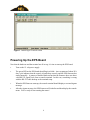
Operating the EPS Console Startup When the EPS console is powered up, the terminal will get an initial menu display like this: RESET: DB ME2 Electronic Position Sensor 1.0 11-16-02 10:16:56 p Position servo mode s Speed servo mode d Position display > The RESET line at the top reports that a board reset has occurred and displays a hardware register diagnostic value, used only for troubleshooting. If the reset was the result of a fault condition, there may be additional diagnostic information displayed on this line. Next comes a signon message that identifies the board and firmware version. Below the signon message is the console menu. Console Menu The console menu has three keystroke options for operating the EPS evaluation board. These will be described in detail below. Below the list of options is the ‘>’ prompt. The terminal cursor waits at that prompt for input from the keyboard. Besides the displayed menu commands, there are two other control keystrokes that you should know about: C SPACEBAR causes the menu to be redisplayed. C ESC shuts down any motor activity and turns off the motor current. 5 Position Display Command Press ‘d’ at the menu prompt to cause the console to begin a continuous display of the motor position and rotational speed. It continues to display and update the position until another character is received from the console. It displays in the following format: position=123.4 RPM=567 The position is in units of degrees of rotation, relative to an electrical zero position defined by the motor rotor magnets. Since the rotor contains four pole pairs, the electrical zero-position repeats every 90 degrees. At initialization time, the Electronic Position Sensing software arbitrarily assumes that the current 90 degree arc contains the zero position. The position display is what the Electronic Position Sensing technology is about. Rotate the motor by hand and watch the numbers change! The position sensing is used for the critical job of controlling motor commutation — switching stator windings as the motor rotates. Some type of position sensing is always needed to control commutation in brushless DC motors. The EPS sensing has much more resolution than necessary for commutation, so it can also be used for other purposes such as to provide feedback for position and speed servos, or for sensing mechanical position as needed for system-level operations. Position Servo Press ‘p’ at the menu prompt to start the position servo. It will prompt you for a target position (in degrees). Type an integer (which can be negative) and press RETURN (also known as ENTER on many PC keyboards). The motor will rotate to that position and actively attempt to maintain it. This position servo is built to demonstrate a use of Electronic Position Sensing. There is nothing particularly special about the servo itself, only that it can operate without any external encoder or sensor on the motor shaft. This particular servo is implemented to interpret the number as an absolute position within a single revolution of the motor. Asking for a position of 360 degrees or 720 degrees is the same as position 0. The motor will take the shortest rotation to get to the target position, so it may go either left or right to reach it. The servo could as easily have been implemented to go multiple revolutions to reach a requested target position, but we arbitrarily chose this definition. The position servo will continue to maintain position until commanded to do otherwise. The console is active while servoing, you can change modes or ask for position display. You can also press ESC to terminate the servo and shut off the motor. 6 Speed Servo Press ‘s’ at the menu prompt to start the speed servo. It will prompt you for a target speed (in RPM). Type an integer (which can be negative) and press RETURN. The motor will ramp to the requested speed. The motors used on the evaluation units are capable of about 2800 RPM when used with a 12V power supply. If you ask for a speed faster than that, the motor will run at its maximum speed. The speed servo is simply another demonstration of a use of Electronic Position Sensing, and is not itself very special. Controlling the speed of a free-running (unloaded) motor with low friction tends to be somewhat unstable. The position display will show some RPM variations, especially at low speeds. For specific applications, we would tune a servo for the required speed and loading range. The motor will maintain speed until commanded to do something else. You can command a new speed or position at any time, or use the position display mode. Press ESC to shut off the motor and let it coast to a stop. 7 Principles of EPS Operation For background, here is a brief overview of how the Electronic Position Sensing works. Impedance Saliency Most brushless DC motors exhibit a phenomenon called saliency, which means that the impedance of the stator windings changes depending on the rotational position of the motor rotor magnets relative to the stator coils. Some research has been done into using the saliency to sense motor position using introduced sense carriers or pulses that are superimposed on the motor drive current. Mountain Engineering II’s Electronic Position Sensing circuit is different because it uses only the winding drive currents themselves to do the sensing. Measuring inductance changes requires an AC stimulus. The EPS circuit uses the AC component of the pulse-width modulation (PWM) that is used to drive the motor windings. Most motor drives use PWM because it allows efficient variable-current control while minimizing heat losses in the drive transistors. The AC component of the PWM signal is more than sufficient for the needed impedance measurement. Measuring the absolute inductance of the stator windings is difficult and the result is affected by many factors including DC current level and temperature. Another unique feature of the Mountain Engineering II EPS is that it measures the ratio of impedances between two adjacent windings, using a circuit configuration similar to a Wheatstone bridge. The ratiometric measurement cancels out many of the factors that could disrupt the position measurement. Back EMF As the motor rotates, it generates its own internal voltage called Back EMF. This is an AC signal caused by voltages induced by the moving magnetic field of the rotor as it passes through the stator coils. The Back EMF is widely used for sensing motor rotational position, but it has the drawback that the motor must be rotating to generate a Back EMF signal, so there is no position information when the motor is stopped (or rotating slowly). This is not acceptable for many applications that require position sensing or control when the motor is stopped. Mountain Engineering II’s EPS system operates well at stop and low RPMs. At higher RPMs, it may be necessary for the PWM to reach very high duty cycles, and it can be difficult to use a very short pulse to do the impedance ratio measurement. This is a predictable effect and can be managed, but we found it easier to switch modes and use the Back EMF signal for position sensing at higher speeds. There is a wide overlap in speed for usable signals from the impedance ratio measurement and from Back EMF. In the evaluation unit, we arbitrarily switch to Back EMF sensing when speed exceeds 380 RPM (in either direction) and switches back to impedance ratio mode when speed decreases below 345 RPM. This mode switch is invisible to the user. 8 Initialization At startup, the Electronic Position Sensing must resolve an ambiguity. The rotor contains a sequence of alternating magnetic north and south poles. The saliency effects of a north pole are approximately the same as of a south pole, so the EPS can’t distinguish between them easily. To resolve the ambiguity, the EPS drives short high-current pulses through each of the three windings. At high currents, there are nonlinearities in the stator coils (magnetic saturation) which make the effective inductance different depending on the presence of a north or south magnetic field. With only one set of pulses, the EPS determines the approximate orientation of the rotor and can then begin normal operation with impedance ratio sensing. When you first power up the EPS evaluation unit, you may be able to hear a soft “brrrp” from the motor windings from the initialization pulses. 9 Adapting EPS to Your Application Mountain Engineering II’s Electronic Position Sensing can work with most brushless motors. The motor requirements are: C The stator must exhibit impedance saliency. Saliency is not usually specified in the motor data sheets so a motor may need to be empirically tested to determine suitability. A preliminary test for saliency is to hook an inductance meter (such as a handheld LCR meter) across the motor winding, then rotate the motor by hand and see if the inductance changes depending on rotational position. For a more sophisticated assessment, send a sample motor to Mountain Engineering II and we can quickly evaluate it. C Our experience is with three-phase brushless motors. The concept should work with stators with more than three phases, but more development would be needed. C The motor should be configured in a Wye configuration, with the center-node available with an external wire to be used by the EPS circuits. We have tested a number of different motor designs of various sizes and mechanical configurations. So far, all tested motors have shown sufficient saliency to work with our EPS. This gives us confidence that the great majority of motors can be used. The EPS evaluation board is specifically laid out for one particular motor and for ease of use in a demo. It will probably not be suitable as is for most specific applications. Another important note: the EPS circuitry need not be mounted directly on the motor. The evaluation board is mounted on its motor for convenience in handling, but it will operate just as well if it is unscrewed and rotated away from the motor. (If you try this, take care that the motor winding leads do not short against the motor housing.) The only limits on placement of the EPS circuitry would come from electrical noise considerations — long leads would mean more noise in the EPS sensing signals as well as causing more radiated EMI from the winding drivers. Mountain Engineering II is ready and able to help you implement Electronic Position Sensing for your specific application and motor. We can do the entire implementation for you, or we can train your staff in the technology so you can do it yourself. ME II is a consulting and technology company, and we’re accustomed to working with our clients to help with their product development. Please call us any time if you would like to discuss the EPS technology or any other area we might be able to help you with! 10