1
Microprocessors are difficult to test-many failure modes
exist and access to internal components is limited.
Design techniques that enhance testability can reduce
the impact of these constraints.
Ng
PP
El
El
-
Testability refers to the ease with which the
presence and perhaps the location of a fault or faults
within a system can be discovered. It has become a
significant factor influencing both the lifetime cost
and initial manufacturing cost of a digital system.
Current design trends emphasize the use of complex
components employing large scale integration. The
key component in many such systems is a microprocessor-a programmable processor consisting of a
small number of integrated circuits or often just a
single IC. The entire digital system takes the form of
a microcomputer comprising a microprocessor which
acts as the central processing unit or system controller, ROM and RAM, and input/output circuits.
Because of the complexity of these components,
problems arise in testing microprocessor-based
systems and in designing them to be easily testable.
A digital system is tested by applying a sequence
of input patterns (tests) which produce erroneous
responses when faults are present. Fault detection
tests, i.e., go/no-go tests, are intended to determine
whether or not a system contains a fault. Fault location tests attempt to isolate a fault to a specific component, preferably an easily replaceable one.
A system has good testability if a high level of fault
coverage can be achieved at an acceptably low cost.'
F^ault coverage is the fraction of faults that can be
detected or located within the UUT-unit under test.
MLicroprocessor-based systems are difficult to test
for several reasons:
* The number of possible faults is extremely large.
An LSI circuit contains thousands of basic components (gates) and interconnecting lines, all individually subject to failure.
* Access to internal components and lines is
severely limited by the number of I/O connecMarch 1980
Testability
Considerotions in
Microprocessor-Based
Design
John P. Hayes
University of Southern California
Edward J. McCluskey
Stanford University
*
tions available. A typical microprocessor may
contain 5000 gates but only 40 I/O pins.
Because of the large number of possible faults, a
successful test will require a large number of test
patterns.
The system. designer
may not have a complete
description of the ICs used in the UUT. Microprocessor specifications typically comprise register-level block diagrams, a listing of the microprocessor's instruction set, and some information on system timing.
* New and complex failure modes such as pattern
sensitivity occur.
These difficulties can be greatly reduced by using
design techniques specifically aimed at enhancing
testability.
Microprocessor testing is of interest in many different situations-semiconductor component manufacturing, test equipment design, system design, and
system maintenance. We will focus on testing from
the design viewpoint. We will also restrict our attention to functional testing, which is only concerned
with the logical behavior of the UUT.
*
Testing methods
Every testing procedure involves the generation of
test data (input test patterns and output responses),
application of the test patterns to the UUT, and evaluation of the responses obtained. Many different
testing approaches have evolved, distinguished by
the techniques used to generate and process test
data. They can be divided into two broad categories-concurrent (implicit) and explicit.
0018-916218010300-0017S00.75
1980 IEEE
17
In concurrent approaches, data patterns from normal computation serve as test patterns, and built-in
monitoring circuits detect faults. Thus testing and
normal computation can proceed concurrently. Parity checking is the most common form of concurrent
testing.2
In explicit approaches, special input patterns serve
as tests; hence normal computation and testing occur
at different times. Explicit tests can be applied by
test equipment external to the UUT (external testing)
or they can be applied internally (self-testing). Even if
concurrent testing is used for system maintenance,
explicit testing is necessary for manufacture and
system assembly. Specific test pattern generation
procedures are required. The test patterns are produced either manually, by a design or test engineer,
or automatically, by special hardware- or softwareimplemented algorithms called test generation programs. Manual test generation is widely used. The
set of test patterns with the correct responses is
called a fault dictionary. Testing based on storing
such test data is called stored response testing.
The cost of storing test pattern responses can be
reduced by using a technique called comparison testing. Note that it may still be necessary to store the
test patterns themselves. Comparison testing makes
use of several copies of the UUT, each processing the
same input signals; faults are detected by comparing
the responses of all the units. A response differing
from that of a known fault-free unit pinpoints a faulty
unit. This technique can be implemented with as few
as two copies of the UUT, one of which-the so-called
gold unit-acts as a reference against which the
other is compared.
Stored response testing may be contrasted with
algorithmic testing, in which the test data is computed each time the UUT is tested. The algorithmic
approach requires some rapid, and therefore simple,
method for determining test data. A common test
pattern source is a high-speed (hardware or software)
counter that generates sequencesof test patterns in a
fixed or pseudo-random order.
Another way of obtaining the good response Ro is
for the test pattern generator to compute it. This approach is well-suited to testing microprocessors, because many of the functions to be tested are defined
by algorithms programmed into the UUT.
High-speed test generators, particularly algorithmic testers, can produce huge amounts of response data whose analysis and storage can be quite
difficult. Compact testing methods attempt to compress the response data R into a more compact form
f(R), from which the UUT fault status information in
R can be derived. The compression function f can be
implemented with simple circuitry. Thus, compact
testing entails little test equipment and is especially
suited for field maintenance.
A compact testing method called transition counting computes the number of logical transitions (a 0
changing to a 1 and vice versa) occurring in the output response at the test point. Transition counting
has been implemented in a number of -commercial
testers and appears to provide acceptable fault
18
coverage.3-5 It has the advantage of being insensitive
to normal fluctuations in signal duration and so is
especially useful for testing asynchronous circuits.
Similar compact testing schemes, such as l's counting, have also been proposed.6'7
Recently, Hewlett-Packard Corporation proposed
a compact testing scheme called signature analysis,
intended for testing microprocessor-based systems.8'9
The output response is passed through a 16-bit linear
feedback shift register whose contents f(R) (after all
the test patterns have been applied) are called the
(fault) signature; f(R) is recorded or displayed as a
four-digit hexadecimal number.
Faults and tests
Every testing procedure diagnoses a particular
class of faults, -although in practice these faults are
not always well-defined. An explicit fault model is
necessary, however, if the fault coverage of a set of
tests is to be determined.
Functional faults. The UUT can be regarded as an
n-input, m-output, s-state finite-state machine-an
(n,m,s,)-machine for short. The functional fault
model, perhaps the m-ost general of the useful fault
models, allows an (n,m,s)-machine to be changed by a
fault to an (n, m,s ')-machine, where s 'does not exceed
s. Under this model a combinational circuit, which is
an (n, m, 1)-machine, always remains combinational
when faults are present. To test a combinational circuit M for all functional faults, it is necessary and sufficient to apply all 2n possible input patterns to M. In
effect, this exhaustively verifies M's truth table and
thereby provides complete fault coverage. Although
this approach requires a large number of tests, it can
easily and rapidly generate them. This type of testing
can sometimes be applied to the combinational subcircuits of a sequential UUT. When the circuit under
test must be treated as sequential (s> 1), complete
detection of functional faults requires a special type
of test called a checking sequence. The theory of
checking sequences is well-developed,10'11 but unless
s is very small, checking sequences are extremely
long and difficult to generate. We now illustrate an
application of the functional fault model to a specific
class of microprocessors.
Testing a simple bit-sliced microprocessor. 12 A bitsliced microprocessor is an array of n identical ICs
called slices, each of which is a simple processor for
operands of length k bits, where k is typically 2 or 4.
The interconnections between the n slices- are such
that the entire array forms a processor for nk-bit
operands. The simplicity of the individual processors
and the regularity of the array interconnections make
it feasible to use systematic methods for fault analysis and test generation. Unfortunately, the more
widely used non-bit-sliced microprocessors do not
share these properties.
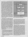
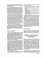
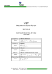
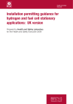
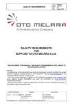
Figure 1 shows a circuit model for a 1-bit processor
slice which has most of the features of a commercial
device such as the Am2901.'3 (The main omission is
COMPUTER
the logic circuitry for implementing carry-lookahead.) This circuit consists of six basic modules, two
of which are sequential (registers A and T) and four of
which are combinational (the shifter, the two multiplexers, and the ALU). The ALU can perform addition, subtraction, and the standard logical operations. Each module may fail according to the foregoing functional model, but only one module is allowed
to be faulty at a time. A complete test set for this circuit must apply all possible input patterns to each
combinational module and a checking sequence to
each sequential module. In addition, the responses of
each module must be propagated to the two primary
output lines. The tests required by the individual
modules are easily generated because of the simplicity of the modules, a direct consequence of the small
operand size (k = 1). The module tests can be overlapped in such a way that 114 test patterns suffice for
testing the entire circuit. Note that the six-input
ALU alone requires 64 test patterns. The number of
test patterns produced in this manner is considerably
less than the number generated for comparable processors by conventional heuristic techniques.14
An important property of this type of processor slice
is the fact that the tests for a single slice can easily be
extended to tests for an array of the slices. In fact, an
array of arbitrary length can be tested by the same
number of tests as a single slice, a property called
C-testability.15 Note that the use of carry-lookahead
eliminates C-testability.
Stuck-line faults. The most widely used fault model
for logic circuits is the SSL-single stuckline-model, which allows any interconnecting line to
be stuck at logical 1 or stuck at 0. In the SSL model
only one line is allowed to be faulty, and the circuit
components-gates, flip-flops, and the like-are
assumed to be fault-free. Clearly SSL faults form a
small subset of functional faults. This model covers
many common physical faults. Several distinct test
generation methods have been developed for SSL
faults,10 with Roth's D-algorithm16'17 the best known
among them. Complete test sets of near-minimal size
can be generated for SSL faults in combinational
logic circuits. However, sequential circuits-even
those of moderate complexity-stiU present serious
problems. Since a microprocessor-based system is a
very complex sequential circuit, it is generally not
feasible to analyze it completely using the classical
gate-level SSL model.
In practice, tests for SSL faults are often restricted
to the following cases:
* faults affecting the external I/O pins of each IC
or the I/O connections of the principal combinational or sequential modules within the IC;
* faults causing the main information transmission paths, e.g., buses, to become stuck at 1 or 0;
and
* faults causing the major state variables to
become stuck at 1 or 0 (such faults usually correspond directly to SSL faults in the associated
registers and memory elements).
March 1980
Figure 1. An easily testable 1-bit processor slice.
Note that these SSL-type faults can be identified
from a register-level description of the UUT. They
define a restricted SSL fault model which is widely, if
implicitly, used in testing complex digital systems.
To detect these restricted faults, it is necessary to
verify that the lines and variables in question can be
set to both the 0 and the 1 values. Thus a basic test for
a memory element such as a microprocessor register
is to verify that a word of O's and a word of l's can be
written into and read from it.
Pattern-sensitive faults. Another useful way to
model faults in LSI circuits is to consider interactions
between logical signals that are adjacent in space or
time. Such a fault occurs when a signal x causes an adjacent signal y to assume an incorrect value. Faults of
this type are termed PSFs-pattern-sensitive faults.
There are many physical failure modes that produce
pattern sensitivity. For example, electrical signals on
conductors in close spatial proximity can interact
with one another. The high component and connection densities characteristic of LSI aggravate this
problem. Another instance of pattern sensitivity is
the failure of a device to recognize a single 0 (or 1) that
follows a long sequence of l's (or O's) on a particular
line; this time-dependent PSF is a consequence of unwanted hysteresis effects. PSFs are particularly
troublesome in high-density RAM ICs. Since microprocessors often contain moderately large RAMs,
they too are subject to PSFs.18
A variety of heuristic procedures have been developed to detect PSFs in memories.1019-21 Since most
PSF tests were derived empirically, their underlying
fault models are unclear, thus making it difficult to
determine their fault coverage. Attempts have been
made to develop formal fault models for some kinds
of PSFs.22,23
A Galpat test of a one-megabit RAM
woiild take about 30 hours.
PSFs provide a good illustration of the testing
problems caused by rapidly increasing IC component
densities. The widely used Galpat test'0 requires
about 4n2 patterns to check an n-bit RAM. If each
test pattern takes 100 ns to apply, then a 4K-bit
(4096-bit) RAM can be tested by Galpat in about 2
seconds. However, a 1M-bit (1,048,576-bit) RAMexpected to appear shortly on a single VLSI chip24would require about 30 hours at the same 100-ns-pertest rate.
Testing microprocessor-based systems
In practice, tests for microprocessor-based systems usually exercise the UUT by applying a representative set of input patterns and causing those patterns to traverse a representative set of state transitions. In each case the decision on what constitutes a
representative set is based on heuristic considerations. The faults being diagnosed may not be specifi-
cally identified, but they can often be related to the
fault models discussed above.
Programmed tests. Much of the uniqueness and
power of a microprocessor-based system lies in the
fact that it is program controlled. Thus a natural tool
for system testing is a test program executed by the
UUT's internal microprocessor. Such a program applies appropriate test patterns to the UUT's major
register-level modules, all of which should be accessible via the UUT instruction set. Typically, such
modules are exercised by input patterns that have
been derived heuristically and are based on the
modules' functions.
A disadvantage of this approach is the absence of a
suitable register-level fault model establishing a correspondence between instruction or module failures
and the underlying physical faults. Thatte and Abraham2526 have recently done some interesting work
towards such a model.
A test program for a microprocessor is usually
organized into a sequence of steps, each testing a
related group of instructions or componenrts. Once a
group has been proven fault-free, it may then be used
to test other groups. The selection and sequencing of
these steps are complicated by the fact that considerable overlap exists among the components affected by different instructions.
Constructing an 8080 testprogram.27 The 8080, introduced by Intel Corporation in 1973, is one of the
most widely used microprocessors. It is an 8-bit
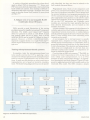
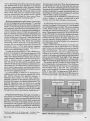
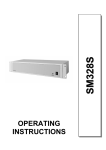
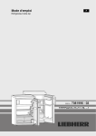
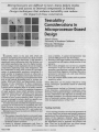
machine of fairly conventional design.28 A registerlevel description (see block diagram, Figure 2) is adequate for applying heuristic fault models such as the
restricted SSL model. The 8080 contains a simple
8-BIT INTERNAL BUS
Figure 2. Architecture of the 8080 microprocessor.
COMPUTER
arithmetic-logic unit and six 8-bit general-purpose
registers; the latter may be paired to form three 16-bit
registers (16 bits is the main memory address size).
Table 1 lists the main steps in an 8080 test program.27 The 8080-based UUT is assumed to be connected to an external tester that has access to the I/O
lines comprising the 8080 data, address, and control
buses. First, the tester resets the UUT. Then it increments the 16-bit program counter PC through all
its 65,536 states. The tester does this by placing a
single instruction NOP (no operation) on the data (input) lines of the 8080 under test and causing the 8080
to execute the instruction repeatedly. The effect of
NOP is to increment the PC and cause it to place its
contents on the outgoing address lines where the
tester can observe and check them. This checking can
be done rapidly by comparing the PC state to that of a
hardware or software counter in the tester which is incremented on-line in step with the PC.
The next step is to test the various general-purpose
registers by transferring 8-bit test patterns to and
from them and checking the results. All possible test
patterns may be used, because their number (256) is
small and they are easy to generate algorithmically.
The tests are implemented by several data transfer
instructions-MOV, LXI, PCHL, which are themselves also tested. After a pattern is applied to a
Table 1.
The main steps in a test program for an 8080-based
system.
1. Reset the 8080 UUT.
2. Test the program counter PC by incrementing it through all its
states via the NOP instruction.
3. Test the six 8-bit general-purpose registers by transferring all
possible 256 test patterns to each register, in turn, via the PC.
4. Test the stack pointer register by incrementing and
decrementing it through all its states; again access it via the
PC.
5. Test the accumulator by transferring all possible test patterns
to it via previously tested registers.
6. Test the ALU and tlags by exercising all arithmetic, logical,
and conditional branch (flag-testing) instructions.
7. Exercise all previously untested instructions and control lines.
register R, the tester can inspect the contents of R by
transferring them to the PC via the high-level
register HL. (The PCHL instruction which swaps the
contents of PC and HL is used; the 8080 lacks instructions for transferring data directly between the PC
and other registers.) Since the PC was tested in the
first step, its contents can be taken to be correct, and
they can be observed directly via the address bus.
(Smith29 discusses some pitfalls of testing 8080
registers in this way.) The remaining steps of the test
program exercise the other components and instructions of the 8080 in a similar manner. Unfortunately,
little data is available on the fault coverage of this
type of test program.
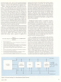
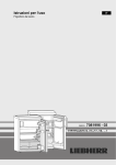
Testing the entire system. A complete microprocessor-based system can be tested by using its
microprocessor as the primary source of test patterns. Consider the problem of testing a system with
a typical bus-oriented architecture (Figure 3.) I/O
device testing is not considered here, since it varies
from device to device. Again we assume that there is
an external tester that has access to the various
system buses. In addition, this external tester is able
to disconnect parts of the system from the buses durifig testing; this can often be done either electrically
or mechanically. Let us consider the main steps in a
general system testing procedure.30
First, a simple test is performed on the microprocessor to determine if one of its main components, the
program counter PC, is operational. As discussed
earlier, this can be done by making the PC traverse all
its states, causing it to place all possible address patterns on the system address bus. It is necessary to
isolate the microprocessor from the data bus during
this test so that the external tester can supply the instructions needed to increment the PC. As in the case
of the 8080 discussed earlier, the tester need only
place a single instruction-NOP-on the microprocessor's data input lines to make the PC increment
continuously. While the PC is incremented-a mode
of operation called free-running, the external tester
monitors and checks the signals appearing on each of
1/0
DEVICES
Figure 3. External testing of a microprocessor-based system.
March 1980
the system's address lines. It is relatively simple to increase controllability and observability.34-36 The
do this monitoring via- compact testing techniques following list is representative:
like signature analysis.
* Allow all memory elements to be initialized
before testing begins, preferably via a single
Next, the system ROMs are tested with the microreset line.
processor still in free-running mode. During this test
* Provide a means for opening feedback loops durthe RAMs are disconnected from the data bus. Since
ing testing.
the microprocessor generates all memory addresses,
* Allow external access to the UUT's clock circuits
it causes every ROM location to be accessed
to permit the tester to synchronize with, or
automatically. The tester monitors the signals which
disable, the UUT.
represent the ROM contents as they appear on the
* Insert multiplexers to increase the number of indata bus. Since the ROM contents are fixed, a fixed
ternal points which can be controlled or observed
signature can easily be associated with each ROM.
from the external pins.
At this point the microprocessor, ROMs, and sysAn important systematic design technique for intem buses have been checked. The remaining parts of
the testability of LSI devices, including micreasing
proexercising
via
specific
tested
are
the system
is the scan-in/scan-out method
croprocessors,
grams, which may be stored in the external tester or
and Angell.37 The LSI chip is
Williams
by
described
in the UUT's ROMs. The RAMs can be tested by proits
memory elements can be
all
that
so
designed
grams such as Galpat. The I/O interface circuits nor- linked to form a shift register,
during testing.
mally resemble memory devices, and therefore can be The circuit is tested by loading a SR,
into SR
pattern
test
In
order
tested by memory-oriented check programs.
the cirof
part
combinational
the
allowing
in),
(scan
to do this under control of the UUT microprocessor,
response
the
out
reading
then
and
to
respond,
cuit
the output ports can be jumper-connected to the inSR (scan out). The scan-in/scan-out approach
put ports, a technique called loop-back.31'32 This lets from
advantages-test generation is reduced
several
has
the CPU send a test pattern to an output port and to the relatively
easy task of testing a combinational
read it back (i.e., check it) via an input port.
circuit, and very few extra gates or pins are required.
All the tests outlined so far can be implemented with A version of this technique called LSSD-level-sensia small subset-mostly NOP, LOAD, and STORE-of tive scan design-is used in the recently introduced
the microprocessor's instruction set. The other in- IBM System/38 computer.38
structions must still be exercised, which can be done
along the lines of the 8080 tests described in the example above.
Self -testing systems
Design for testability
The difficulty and expense of testing digital I-Cs
and systems constructed of digital ICs have become
so great that there is widespread agreement that ICs
should be designed to facilitate testing. The techniques for designing "testable ICs" fall into two categories-design guidelines (rules of thumb to be
followed in order to obtain testable circuits) and
systematic procedures or structures aimed at producing testable circuits. The systematic approaches are
surveyed in a paper by McCluskey.1
Two key concepts, controllability and observability, relate to many of the methods for designing testable circuits. Controllability may be defined informally as the ease with which test input patterns can
be applied to the inputs of a subcircuit, S(i), by exercising the primary inputs of the circuit S. Observability is the ease with which the responses of S(i) can be
determined by observing the primary outputs of S.
These intuitive concepts have been quantified by
Stephenson and Grason,33 so that measures of controllability and observability- can be determined
directly from a gate- or register-level circuit for S.
These measures can be used to predict the difficulty
of generating test patterns for S.
Logic designers have compiled a set of design
guidelines to simplify testing which generally try to
22
So far, our discussion has been concerned with external testing methods in which the bulk of the test
equipment is not a part of the UUT. As digital systems grow more complex and difficult to test, it
As digital systems grow more complex,
built-in test techniques become
more attractive.
becomes increasingly attractive to build test procedures into the UUT itself. Some self-testing ability
is incorporated into most computers, mainly via
coding techniques. A few machines have been designed with essentially complete self-testing, notably
telephone switching systems39 and spacecraft computers.40 In the last few years comprehensive selftesting features have become common in microprocessor-controlled instruments such as logic analyzers. The Commodore PET, a personal computer
based on the 6502 microprocessor, is delivered with a
self-testing program considered to have fault
coverage sufficient to serve as the sole go/no-go test
used in manufacture.3'
Coding techniques. The great advantage of coding
techniques is their precisely defined level of fault
coverage, attained with little overhead in extra hardCOMPUTER
ware or processing time. Some codes can give almost
any desired level of error detection or correction,
although implementation costs generally increase
with the fault coverage desired.2'41 The most widely
used error-detecting and correcting codes are the
parity check codes. They are mainly used for checking data transmission and storage devices. Special
codes have been developed for some types of functional units, particularly arithmetic units.42*
Hardware-implemented self-testing. General logic
circuits, if designed to be self-checking,2'43'44 can offer
advantages similar to those provided by coding techniques. A self-checking logic circuit is one whose output responses constitute an error-detecting code. A
variety of techniques for designing self-checking circuits are known, many of which are practical.2 Indeed, it is feasible to build a computer which performs
all testing by means of self-checking circuits and
similar mechanisms. Carter et al.45 show that the cost
of such a computer is relatively low, if current LSI
technology is exploited. They found that complete
self-testing could be achieved in a System/360-type
machine with an increase of less than 10 percent in
component count. A VLSI fault-tolerant computer
proposed by Sedmak and Liebergot46 also makes extensive use of self-checking circuits.
On-chip electrical monitors,47'48 are a different approach to the design of self-checking hardware. This
technique, which has been applied to ECL-type LSI
chips, uses special electrical circuits that can detect
small changes in parameters such as current or resistance. A monitor circuit is typically connected to
each I/O line of the chip, and the combined output
signals from the on-chip monitors are connected to an
extra output pin. On-chip monitors of this kind detect
short-circuits, open circuits, and similar interconnection faults. This promising testing method is new and
has seen little application so far.
It is also possible to make an IC self-testing by
building into it all the circuitry required for a compact testing technique like signature analysis. A
relatively small amount of extra logic sufficesbasically a counter for test pattern generation and a
feedback shift register for signature generation. The
fault-free signatures may be stored in an on-chip
ROM for comparison with the signatures produced
during testing. An experiment simulating this approach and using a modified version of the Am2901
microprocessor slice is described by Zweihoff et al.49
microprocessor under test. Thus, the microprocessor
is responsible not only for executing the test programs, but also for scheduling their execution and interpreting their results. In self-testing systems, test
program execution is usually interleaved with normal program execution and is designed to interfere
with the latter as little as possible.
We conclude with an example of a microprocessor
system designed to achieve a high level of selftesting-and some fault tolerance-at a low cost.
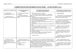
A self-testing microprocessor-based system. 32 This
machine, developed at E-Systems Inc., was designed
as a communications controller. The system includes
a CPU, ROMs, RAMs, and I/O interface circuits, all
of which are tested automatically by a self-test program. This program is stored in a 1K-byte ROM within the CPU itself. It is executed in background mode,
being invoked during normal processing by a lowpriority interrupt signal. All major subsystems are
tested in sequence, starting with the CPU. Detection
of a fault causes an indicator light to be turned on in
an LED display panel.
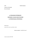
Figure 4 shows the CPU structure. It contains two
microprocessors, one of which serves as a standby
spare in the event of the failure of the active (controlling) microprocessor. The active microprocessor
must access and reset a timer T at regular intervals.
Failure to do so causes a time-out circuit to transfer
control of the systems to the back-up microprocessor
and to turn on the CPU fault light. If the back-up
microprocessor is working properly, it subsequently
resets T, causing the fault indicator to be turned off.
The memory and I/O circuits are tested using the
general approaches discussed earlier. The ROMs are
tested by accessing a block of words from each ROM
and summing them in the CPU. The accumulated
word is then compared to a check word stored in the
ROM. If they differ, the appropriate ROM fault in-
dicator is switched on. If desired, the ROM status can
be written into RAM, thus allowing the system to
Programmed self-testing. Although it is feasible to
rely entirely on hardware checking circuits for selftesting, it is often more economical to use self-testing
software, especially when off-the-shelf components
with little or no built-in checking circuitry are used.
The heuristic test programs discussed in the preceding section can readily be modified for self-testing.
The role of the external tester is taken over by the
*See also the paper by D.
K. Pradhan and J. J.
Stiffler, "Error-
Correcting Codes and Self-Checking Circuits," in this issue.
March
19802
Figure 4. The CPU of a self-testing system.
23
identify and bypass the faulty block in the ROM.
This enables the system to operate even with a ROM
fault present.
To test a RAM, each RAM locationXis read in turn
and its contents saved in a CPU register. Then two
checkerboard patterns are applied to X in the standard way. If X passes the test, its original contents
are restored from the temporary register and the next
RAM word is tested.
I/O tests are performed using the loop-back procedure described earlier, in which output ports are
connected to input ports one at a time under CPU control. Test patterns are transmitted through the resulting closed data path and checked for accuracy.
Multimicroprocessor systems. If a system contains a number of microprocessors in the form of a
multiprocessor or computer network, then it may be
possible-and advantageous-to use the microprocessors to test one another. Fault-tolerant computers
such as the UC Berkeley Prime system50 employ this
approach to self-testing. Although few self-testing
systems of this type have been built, some interesting and relevant theory has been developed. Much of
this is concerned with measuring system self-testability by means of graph-theoretical models.10'51'52
The applicability of these models to existing systems
TERMINALS
PURCHASE FULL OWNERSHIP AND LEASE PLANS
PURCHASE
DESCRIPTION
PRICE
12 MOS.
PER MONTH
24 MOS.
36 MOS.
LA36 DECwriter 11 ...........$1,595 $153 $ 85 $ 57
47
69
LA34 DECwriter IV ......... 1,295 124
83
2,295 220 122
LA120 DECwriter Ill KSR
68
VT100 CRT DECscope ...... 1,895 182 101
83
VT132 CRT DECscope
2,295 220 122
68
DT80/1 DATAMEDIA CRT .... 1,895 182 101
57
85
T1745 Portable Terminal .... 1,595 153
T1765 Bubble Memory Terminal 2,795 268 149 101
68
T1810 RO Printer .......... 1,895 182 101
79
T1820 KSR Printer .......... 2,195 210 117
61
90
T1825 KSR Printer ......... 1,695 162
32
47
875
84
ADM3A CRT Terminal
OUME Letter Quality KSR ... 3,195 306 170 115
QUME Letter Quality RO ..... 2,795 268 149 10127
40
71
745
HAZELTINE 1410 CRT .......
39
58
HAZELTINE 1500 CRT ........ 1,095 105
47
69
HAZELTINE 1552 CRT ....... 1,295 124
DataProducts 2230 Printer . 7,900 757 421 284
63
93
DATAMATE Mini Floppy ..... 1,750 168
....
.......
FULL OWNERSHIP AFTER 12 OR 24 MONTHS
1W0o PURCHASE OPTION AFTER 36 MONTHS
ACCESSORIES AND PERIPHERAL EOUIPMENT
ACOUSTIC COUPLERS * MODEMS * THERMAL PAPER
RIBBONS * INTERFACE MODULES * FLOPPY DISK UNITS
PROMPT DELVERY * EFFICIENT SERVICE
Reader Service Number 4
is limited, mainly due to the fact that the testing function in most systems is highly centralized. This situation is likely to change as multimicroprocessor
systems become more common, allowing a high-level
testing capability to be distributed throughout a
system. -
Acknowledgments
The manuscript for this article was prepared using
a DEC Tops-20 system. Final copy and figure preparation was done by Lydia Christopher, whose contribution is gratefully acknowledged. This article is an
abbreviated version of Stanford University Computer Systems Laboratory Technical Report No. 179.
This work was sponsored in part by the Air Force
Office of Scientific Research under Grants AFOSR
77-3325 and 77-3352, by the Joint Services Electronics Program under Contract F44620-76-C-0061,
and by the National Science Foundation under Grant
MCS76-05327.
References
1. E. J. McCluskey, "Design for Maintainability and
Testability," Proc. Government Microcircuits Applications Conf. (GOMAC), Monterey, Calif., Nov.
1978, pp. 44-47.
2. J. Wakerly, ErrorDetecting Codes, Self-Checking Circuits and Applications, American Elsevier, New York,
1978.
3. N. P. Lyons, "FAULTRACK: Universal Fault Isolation Procedure for Digital Logic, " 1974 IEEE Intercon
Technical Program, New York, Mar. 1974, paper no.
40/2.
4. J. P. Hayes, "Transition Count Testing -of Combinational Logic Circuits," IEEE Trans. Computers, Vol.
C-25, No. 6, June 1976, pp. 613-620.
5. J. Losq, "Efficiency of Random Compact Testing,"
IEEE Trans. Computers, Vol. C-27, No. 6, June 1978,
pp. 516-525.
6. J. P. Hayes, "Check Sum Methods for Test Data Compression," J. Design Automation and Fault-Tolerant
Computing, Vol. 1, No. 1, Oct, 1976, pp. 3-17.
7. K. P. Parker, "Compact Testing: Testing with Compressed Data," Proc. 1976 Int'l Symp. Fault-Tolerant
Computing, Pittsburgh, June 1976, pp. 93-98.*
8. G. Gordon and H. Nadig, "Hexadecimal Signatures
Identify Troublespots in Microprocessor Systems,"
Electronics, Vol. 50, No. 5, Mar. 3, 1977, pp. 89-96.
9. A. Stefanski, "Free Running Signature Analysis Simplifies Troubleshooting," EDN, Vol. 24, No. 3, Feb. 5,
1979, pp. 103-105.
10. M. A. Breuer and A. D. Friedman, Diagnosis and
ReliableDesign ofDigital Systems, Computer Science
Press, Woodland Hills, Calif., 1976.
11. F. C. Hennie, "Fault Detecting Experiments for Sequential Circuits," Proc. 5th Ann. Symp. Switching
Theory and Logical Design, Nov. 1964, pp. 95-110.
12. T. Sridhar and J. P. Hayes, "Testing Bit-Sliced Microprocessors," Digest of Papers-Ninth Ann. Int'l
Symp. Fault-Tolerant Computing, Madison, Wisc.,
June 1979, pp. 211-218.*
COMPUTER
RASTER DISPLAY SYSTEM DESIGN NOTE 3.
13. The Am2900 Family Data Book, Advanced Micro
Devices, Sunnyvale, Calif., 1976.
14. R. McCaskill, "Test Approaches for Four Bit Microprocessor Slices," Digest of Papers-Memory and
LSI-1976 Semiconductor Test Symp., Cherry Hill,
N.J., Oct. 1976, pp. 22-26.*
15. A. D. Friedman, "Easily Testable Iterative Systems,"
IEEE Trans. Computers, Vol. C-22, No. 12, Dec. 1973,
pp. 1061-1064.
16. G. F. Putzolu and J. P. Roth, "A Heuristic Algorithm
for the Testing of Asynchronous Circuits," IEEE
Trans. Computers, Vol. C-20, No. 6, June 1971, pp.
639-647.
17. J. P. Roth, "Diagnosis of Automata Failures: A
Calculus and a Method," IBMJ. Research and Development, Vol. 10, No. 7, July 1966, pp. 278-291.
18. D. Hackmeister and A. C. L. Chiang, "Microprocessor
Test Technique Reveals Instruction Pattern Sensitivity," ComputerDesign, Vol. 14, No. 12, Dec. 1975, pp.
81-85.
19. W. Barraclough, A. C. L. Chiang, and W. Sohl, "Techniques for Testing the Microprocessor Family," Proc.
IEEE, Vol. 64, No. 6, June 1976, pp. 943-950.
20. W. G. Fee, LSI Testing, 2nd ed., IEEE Computer
Society, Long Beach, Calif., 1978.*
21. E. R. Hnatek, "4-kilobit Memories Present a
Challenge to Testing," ComputerDesign, Vol. 14, No.
5, May 1975, pp. 117-125.
22. J. P. Hayes, "Detection of Pattern Sensitive Faults in
Random Access Memories," IEEE Trans. Computers,
Vol. C-24, No. 2, Feb. 1975, pp. 150-157.
23. R. Nair, S. M. Thatte, and J. A. Abraham, "Efficient
Algorithms for Testing Semiconductor RandomAccess Memory," IEEE Trans. Computers, Vol. C-27,
No. 6, June 1978, pp. 572-576.
24. R. P. Capece, "Tackling the Very Large Scale Problems of VLSI," Electronics, Vol. 51, No. 24, Nov. 23,
1978, pp. 111-125.
25. S. M. Thatte and J. A. Abraham, "User Testing of Microprocessors," Digest of Papers-Exploding
Technology, Responsible Growth-COMPCON
Spring 79, Eighteenth IEEE Computer Society Int7
Con., San Francisco, Feb./Mar. 1979, pp. 108-114.*
26. S. M. Thatte and J. A. Abraham, "A Methodology for
Functional Level Testing of Microprocessors," Digest
of Papers-Eighth Ann. Int'l Conf Fault-Tolerant
Computing, Toulouse, June 1978, pp. 90-95.*
27. A. C. L. Chiang and R. McCaskill, "Two New Approaches Simplify Testing of Microprocessors," Electronics, Vol. 49, No. 2, Jan. 22, 1976, pp. 100-105.
28. Intel8080MicrocomputerSystems User's Manual, Intel, Santa Clara, Calif., Sept. 1975.
29. D. H. Smith, "Exercising the Functional Structure
Gives Microprocessors a Real Workout," Electronics,
Vol. 50, No. 4, Feb. 17, 1977, pp. 109-112.
30. "A Designer's Guide to Signature Analysis," Application Note 222, Hewlett-Packard, Palo Alto, Calif.,
Apr. 1977.
31. E. S. Donn and M. D. Lippman, "Efficient and Effective piC Testing Requires Careful Planning," EDN,
Vol. 24, No. 4, Feb. 2, 1979, pp. 97-107.
32. D. P. Fulghum, "Automatic Self-Test of a Micro-Processor System," Proc. AUTOTESTCON '76, Arlington, Texas, Nov. 1976, pp. 47-52. (Abstracts in IEEE
Trans. Aerospace and Electronic Systems, Vol. AES13, No. 2, Mar. 1977.)
March 1980
How to use a
60Hz raster scan
display for high
resolution,
flicker-free graphics
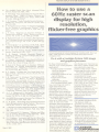
Actual photograph of vectors displayed by Lexidata 3400. Note how
1280 x 1024 resolution virtually eliminates stair-step distortion
of diagonal lines.
Do it with a Lexidata System 3400 image
and graphics processor.
Do these characteristics
describe your vector graphics
application?
* Large number of vectors
must be displayed
simultaneously.
* Selectable erasure of any
part of display.
* High-speed vector
drawing.
* Flicker-free display.
The Lexidata System 3400
has everything you need to
apply state-of-the-art
refreshed raster scan
technology to your most
demanding vector graphics
application. And at a price
that is competitive with other,
less capable display methods.
The 3400 offers resolutions up to 1280 pixels x 1024
lines. It is the only video
processor that can generate a
pixel in nine nanoseconds,
yielding a 60 Hz refresh rate
for flicker-free images. It is
also among the fastest
processors available, handling
burst data transfers from the
host computer at up to two
megabytes per second.
Now you can use a raster
scan display to draw vectors
that aren't jagged when they
should be straight and don't
flicker when they should be
rock steady You can draw
them fast since the 3400's
microprocessor cycle time
change your mind just as
fast since a raster display lets
you selectively erase any
portion of the screen without
redrawing the entire image.
The System 3400 is easy
to use. It is supported by a
comprehensive image
processing operating system
and host computer interface
drivers for such systems as
DEC PDP-11 and VAX, Data
General Eclipse and Nova,
Interdata and HewlettPackard. A repertoire of over
three dozen standard and
optional features assures the
ideal mix of hardware and
software tools for any
application.
can
GET MORE INFORMATION
The System 3400 is a
powerful and versatile
display processor, equally
adept at line-drawing and
tonal-imaging applications
using black-and-white, grayscale, and color displays. Find
out how this system can
improve the performance and
reduce the cost of your computer graphics processing by
writing to the address below
or calling (617) 273- 2700.
a LEXIDATA
37 NORTH
AVENUE, BURLINGTON, MA 01803
33. J. E. Stephenson and J. Grason, "A Testability Measure for Register Transfer Level Digital Circuits,"
Proc. 1976 Int'l Symp. Fault-Tolerant Computing,
Pittsburgh, June 1976, pp. 101-107.*
34. R. G. Bennetts and R. V. Scott, "Recent Developments in the Theory and Practice of Testable Logic
Design," Computer, Vol. 9, No.6, June 1976, pp. 47-63.
35. "Designing Digital Circuits for Testability," Application Note 210-4, Hewlett-Packard, Palo Alto, Calif.,
Jan. 1977.
36. J. Mancone, "Testability Guidelines," Electronics
Test, Vol. 2, No. 3, Mar. 1979, pp. 14-16.
37. M. J. Y. Wiliams and J. B. Angell, "Enhancing Testability of Large-Scale Integrated Circuits via Test
Points and Additional Logic," IEEE Trans. Computers, Vol. C-22, No. 1, Jan. 1973, pp. 46-60.
38. E. B. Eichelberger and T. W. Wiliams, "A Logic Design Structure for LSI Testability," J. Design Automation and Fault-Tolerant Computing, Vol. 2, No. 2,
May1978, pp. 165-178.
39. R. W. Downing, J. S. Novak, and L. S. Tuomenoksa,
"No. 1 ESS Maintenance Plan," Bell System
Technical J., Vol. 43, No.5, Sept. 1964, pp. 1961-2019.
40. A. Avizienis et al., "The STAR (Self-Testing and Repairing) Computer: An Investigation of the Theory
and Practice of Fault-Tolerant Computer Design,"
IEEE Trans. Computers, Vol. C-20, No. 11, Nov. 1971,
pp. 1312-1321.
41. W. W. Peterson and E. J. Weldon, Error-Correcting
Codes, MIT Press, Cambridge, Mass., 1972.
42. T. R. N. Rao, Error Coding for Arithmetic Processes,
Academic Press, New York, 1974.
43. D. A. Anderson and G. Metze, "Design of Totally SelfChecking Check Circuits for m-out-of-n Codes, " IEEE
Trans. Computers, Vol. C-22, No. 3, Mar. 1973, pp.
263-269.
44. W. C. Carter and P. R. Schneider, "Design of
Dynamicaly Checked Computers," Proc. IFIP Congress, Vol. 2, Edinburgh, 1968, pp. 878-883.
45. W. C. Carter et al., "Cost Effectiveness of Self-Checking Computer Design," Digest of Papers-Seventh
Ann. Int'l Conf Fault-Tolerant Computing, Los
Angeles, June 1977, pp. 117-123.*
46. R. M. Sedmak and H. L. Liebergot, "Fault Tolerance
of a General Purpose Computer Implemented by Very
Large Scale Integration," Digest of Papers-Eighth
Ann. Int'l Conf Fault Tolerant Computing, Toulouse,
June 1978, pp. 137-143.*
47. F. B. D'Ambra et al., "On Chip Monitors for System
Fault Isolation," Digest of Technical Papers-1978
IEEE Int'l Solid-State Circuits Conf, San Francisco,
Feb. 1978, pp. 218-219.
48. S. H. Sangani and B. Valitski, "In-Situ Testing of
Combinational and Memory Circuits Using a Compact
Tester," Digest of Papers-Eighth Ann. Int'l Conf
Fault-Tolerant Computing, Toulouse, June 1978, p.
214.*
49. G. Zweihoff, B. Koenemann, and J. Mucha, "Experimente mit einem Simulationsmodell fur Selbst-Testende IC's" ("Experiments with a Simulation Modelfor
Self-Testing IC's"), NTG-Fachberichte, Band 68, Apr.
1979, pp. 105-108.
50. H. B. Baskin, B. R. Borgerson, and R. Roberts,
"PRIME-A Modular Architecture for Terminal-Oriented Systems," AFIPS Conf Proc., Vol. 40, 1972
SJCC, pp. 431-437.
26
51. F. P. Preparata, G. Metze, and R. T. Chien, "On the
Connection Assignment Problem of Diagnosable Systems," IEEE Trans. Electronic Computers, Vol.
EC-16, No. 6, Dec. 1967, pp. 848-854.
52. J. D. Russell and C. R. Kime, "System Fault Diagnosis: Masking, Exposure, and Diagnosability Without Repair," IEEE Trans. Computers, Vol. C-24, No.
12, Dec. 1975, pp. 1155-1161.
*This proceedings, digest, or tutorial is available from the IEEE
Computer Society Publications Office, 5855 Naples Plaza, Suite 301,
Long Beach, CA 90803.
John P. Hayes is an associate professor
of electrical engineering and computer
science at the University of Southern
California. Before coming to USC in
1972 he was a member of the Operations Research Group at the Shell Bene_lux Computing Centre in The Hague,
Netherlands. Currently involved in
teaching and research in fault-tolerant
computing, computer architecture, and
microprocessor-based systems, Hayes is the author of the
book Computer Architecture and Organization (McGrawHill, 1978), and editor of the computer architecture and
systems department of Communications of the ACM. He
was technical program chairman of the 1977 International
Conference on Fault-Tolerant Computing.
Hayes received the BE degree from the National University of Ireland (Dublin) in 1965, and the MS and PhD
degrees from the University of Illinois in 1967 and 1970, all
in electrical engineering. While at the University of Illinois
he participated in the design of the Illiac III computer.
Edward J. McCluskey is a professor of
electrical engineering and computer
science at Stanford University, where
he started the Digital Systems Laboratory (now the Computer Systems Laboratory), a joint research organization
of the electrical engineering and computer science departments. He also
started a computer engineering pro-
gram, a joint MS degree program, and
the Computer Forum-an industrial affiliates program.
McCluskey received the AB summa cum laude in mathematics and physics from Bowdoin College in 1953, and the
BS, MS, and ScD in electrical engineering from MIT in
1953, 1953, and 1956, respectively. The first president of
the IEEE Computer Society and a past member of the
AFIPS Executive Committee, he is currently a member of
the IEEE Fellows Committee. He has been general chairman of the Computer Architecture Symposium, the FaultTolerant Computing Symposium, and the Operating
Systems Symposium. A member of the editorial boards of
DigitalProcesses, Annals of theHistoryofComputing, and
the Journal ofDesign Automation and Fault Tolerant Computing, he is editor of Elsevier North-HoUand's computer
design and architecture series. McCluskey was formerly an
associate editor of the IEEE Transactions on Computers
and the Journal of the ACM.
COMPUTER