1
HG Series
Mercury Displacement Relay
User’s Manual
ISO 9001
Registered Company
Winona, Minnesota USA
Power Controls
Watlow Controls, 1241 Bundy Blvd., P.O. Box 5580, Winona, MN, USA 55987-5580, Phone: (507) 454-5300, Fax: (507) 452-4507
WMDR-XUMN-1097
June 1997
Supersedes: WMDR-XUMN Rev A00
Made in the U.S.A.
Printed on Recycled Paper 10% Postconsumer Waste
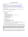
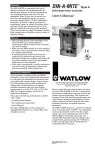
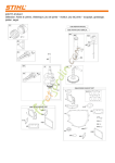
Dimensions
All 35, 50, and 60 Amp Models
30 Amp Models
HG30-XKDX-0000
1 Pole
#8-32
Binding
Head
Screw
#10-#14
A.W.G.
2.00
(51)
Dia.
3.58
(91)
1.94
(49)
1.63
(41)
.21 (5)
Dia.
Mounting
Hole
1.19
(30)
2.25
(57)
NOTE:
Watlow recommends that ring terminal lugs be used
with stranded wire
on all binding head
screw terminals.
“A”
Dimensions
4.62 (117)
4.62 (117)
5.12 (130)
HG35-XLDX-0000
HG50-XMDX-0000
HG60-XPDX-0000
Pressure
Connectors
#4-14 A.W.G.
#4-14 A.W.G.
#1 - 8 A.W.G.
1 Pole
Pressure
Connector
2.00
(51)
"A"
1.94
(49)
1.63
(41)
2 Pole
#8-32 Binding
Head Screw
#10-#14 A.W.G.
4.00
(102)
2.25
(57)
1.19
(30)
.20 (5)
Dia. Mtg.
Hole
2 Pole
.21 (5)
Wide Slot
For #10
Screw
Hole
2.65
(67)
1.94
(49)
Pressure
Connector
40°
Typ.
.21 (5)
Dia.
Mounting
Hole
3.13
(79)
2.62
(67)
4.00
(102)
.21 (5)
Wide Slot
For #10
Screw
Hole
40°
Typ.
.21 (5)
Dia. Mtg.
Hole For
#10 Screw
3 Pole
#8-32
Binding
Head Screw
#10-#14
A.W.G
4.00
(102)
.21 (5)
Wide
Slot
For#10
Screw
Hole 40°
Typ.
.21 (5)
Dia.
Mounting
Hole
3.25
(83)
3.75
(95)
.21 (5)
Wide Slot
For #10
Screw
Hole
40°
TYP.
.21
(5)
Dia. Mtg.
Hole For
#10
Screw
#10-32
Binding
Head
Screw
.25
Typ. Up To #10
A.W.G.
(6)
3.13
(79)
2.65
(67)
3.75
(95)
4.00
(102)
Mercury displacement relay must be
mounted vertically. Failure to do this will prevent the
contacts from turning off, which will supply full
voltage to the load. Failure to follow this guideline
could result in damage to equipment, and personal
injury or death.
ÓWARNING:
2
"A"
1.94
(49)
ÓWARNING:
Up
3.14
(80)
2.62
(67)
Pressure
Connector
3.75
(95)
Mounting
Slot
For #8 To
#10 Screw
3.13
(79)
4.00
(102)
3 Pole
Definite Purpose Relay Foot Print
HG30-XAAX-0000
2.16
(55)
2.65
(67)
2.65
(67)
1.94
(49)
3.13
(79)
4.00
(102)
"A"
1.94
(49)
3.43
(87)
Watlow Series HG Mercury Displacement Relay User’s Manual
Mercury displacement relay contacts
will switch ac current only. Not for use with dc
current. Failure to follow this guideline could result
in damage to equipment, and personal injury or
death.
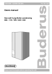
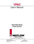
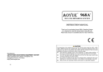
Dimensions
Wiring
∑WARNING:
All 80, 100, and 150 Amp Models
“A”
Dimensions
5.77 (147)
5.77 (147)
6.40 (163)
HG80-XABX-0000
HG1M-XACX-0000
HG2M-XADX-0000
Wiring must conform to
National Electric Code (NEC) safety
standards, as well as locally applicable
codes. Failure to do so could result in
personal injury or death. See page 6 for
fusing recommendations.
Pressure
Connectors:
#1-8 A.W.G.
#1-8 A.W.G.
#1/0 - #2 A.W.G.
çUse copper conductors only.
1 Pole
1 Pole Wiring Example
2.50
(64)
Pressure
Connector
L1
Fuse
120V~(ac)
Fuse
1 Pole
120V~(ac)
Coil
"A"
2.18
(55)
1.88
(48)
Control
(5)
.20 Dia.
Mtg Hole
2.62
(67)
2.13
(54)
L2
Neutral
2 Pole
Heater
2 Pole Wiring Example
5.70
(145)
Pressure
Connector
Fuse
Fuse
Fuse
.27
(7)
Wide Mtg.
Slot
"A"
Fuse
Control
2 Pole
240V~(ac)
Single
Phase
3.78
(96)
2.79
(71)
40°
Typ.
(7)
.27 Dia.
Mtg. Hole
Heater
3.25
(83)
4.70
(119)
Pressure
Connector
3 Pole
3 Pole Wiring Example
208V~ (ac) L1
3 Phase L2
Wye L3
{
(7)
.27 Dia.
Mtg. Slot
"A"
3.78
(96)
2.79
(71)
40°
Typ.
L1 240V~(ac)
} Single
L2 Phase
N
Fuses
Fuse
3 Pole
120V~(ac)
Coil
Control
(7)
.27 Dia.
Mtg. Hole
4.70
(119)
5.70
(145)
5.00
(127)
3-Phase
Wye Heater
Watlow Series HG Mercury Displacement Relay User’s Manual
3
Field Coil Power Requirements
HG30-XAAX-0000
Voltage
24V~ (ac)
120V~ (ac)
208V~ (ac)
240V~ (ac)
24VÎ (dc)
1 Pole
Current
Power
NA
NA
NA
NA
NA
NA
NA
NA
NA
NA
2 Pole
Current
Power
0.456A
10.9VA
0.121A
14.5VA
0.055A
11.4VA
0.063A
15.1VA
0.240A
5.8W
3 Pole
Current
0.510A
0.106A
0.055A
0.062A
0.250A
Power
12.2VA
12.7VA
11.4VA
14.9VA
6.0W
3 Pole
Current
1.270A
0.224A
0.111A
0.128A
0.470A
Power
30.5VA
26.9VA
23.1VA
30.7VA
11.3W
HG30-XKDX-0000
HG35-XLDX-0000
HG50-XMDX-0000
HG60-XPDX-0000
Voltage
24V~ (ac)
120V~ (ac)
208V~ (ac)
240V~ (ac)
24VÎ (dc)
1 Pole
Current
0.235A
0.057A
0.030A
0.035A
0.146A
Power
5.6VA
6.8VA
6.2VA
8.4VA
3.5W
2 Pole
Current
Power
0.529A
12.7VA
0.133A
16.0VA
0.075A
15.6VA
0.087A
20.9VA
0.266A
6.4W
HG80-XABX-0000
HG1M-XACX-0000
HG2M-XADX-0000
Voltage
24V~ (ac)
120V~ (ac)
208V~ (ac)
240V~ (ac)
24VÎ (dc)
1 Pole
Current
Power
0.930A
22.3VA
0.195A
23.4VA
0.097A
20.2VA
0.112A
26.9VA
0.219A
5.2W
2 Pole
Current
Power
2.310A
55.4VA
0.448A
53.8VA
0.280A
58.2VA
0.323A
77.5VA
0.572A
13.7W
3 Pole
Current
Power
5.060A
121.4VA
0.968A
116.2VA
0.482A
100.3VA
0.563A
135.1VA
0.555A
13.3W
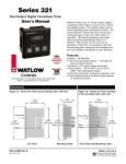
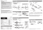
Temperature Control Output to MDR Coil Input
Please refer to the Field Coil Power Requirements when selecting the correct temperature control output.
Example: An HG35-1LD3-X000 requires 224mA to energize the coil and could be used with Watlow
temperature control output options ‘B’ or ‘K’ (i.e. 988A-XXBB-XXXX or 988A-XXKK-XXXX) models. The
best selection is the ‘B’ output option because it includes an RC snubber across the output. If you select
the ‘K’ option, it is recommended that you also purchase a Quencharc® snubber separately (Watlow part
number 0804-0147-0000). Place the snubber across the MDR coil terminals to protect the temperature
control solid state output. When placing the snubber across the coil of a 2 and 3 pole relay, you may have
to add some lead wire to the snubber. The MDR coil is an inductive load and the snubber will reduce the
flyback voltage produced by the MDR coil when it de-energizes. See below.
Quencharc
Snubber
(Purchase
Separately)
Note: Watlow temperature control solid state outputs will not drive VDC coils directly. Refer to the coil
current specifications above and any temperature control output specifications as required by the
application.
Watlow Series HG Mercury Displacement Relay User’s Manual
4
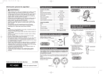
Ordering Information
WMDR-XMNN-1099
HG _ _ - _ _ _ _ - 0 0 _ _
Amperage
30 = 30 Amp
35 = 35 Amp
50 = 50 Amp
60 = 60 Amp
80 = 80 Amp
1M = 100 Amp
2M = 150 Amp
Coil Voltage
1 = 120V~ (ac)
4 = 24V~ (ac)
6 = 24VÎ (dc)
9 = 208/240V~ (ac)
Option
KD = 30 Amp (Standard)
LD = 35 Amp
MD = 50 Amp
PD = 60 Amp
AA = 30 Amp (Definite Purpose
Relay Footprint)
AB = 80 Amp
AC = 100 Amp
AD = 150 Amp
Poles
1 = 1 Pole (Not For Option “AA”)
2 = 2 Pole
3 = 3 Pole
Type
00 = Standard
(Includes Definite Purpose Relay Footprint)
XX = Custom
5
Returns
1. Call Customer Service: 507-454-5300, or
fax: 507-452-4507, for a Return Material
Authorization (RMA) number before returning any
item for repair.
2. Make sure the RMA number is on the outside of the
carton, and on all paperwork returned. Ship on a
freight prepaid basis.
3. A restocking charge of 20% of the net price applies
for all returned stock controls and accessories in like
new condition and within 120 days after shipment.
Non-stock and modified stock items are not
returnable.
4. If the unit is unrepairable, it will be returned to you
with a letter of explanation. Repair costs will not
exceed 50% of the original cost.
Recycle
To provide proper disposal, Watlow accepts used MDRs.
Phone (507) 454-5300 for an Return Materials
Authorization (RMA) number. Contact your Watlow
representative for details.
Warranty
The Mercury Relay is warranted to be free of defects in
material and workmanship for 18 months after delivery to
the first purchaser for use, providing that the units have
not been misapplied. Since Watlow has no control over
their use, and sometimes misuse, we cannot guarantee
against failure. Watlow’s obligations hereunder, at
Watlow’s option, are limited to replacement, repair or
refund of purchase price, and parts which upon
examination prove to be defective within the warranty
period specified. This warranty does not apply to
damage resulting from transportation, alteration, misuse,
abuse or improper fusing.
Watlow Series HG Mercury Displacement Relay User’s Manual
Specifications
Model Number
WMDR-XSPN-1098
HG30-XKDX HG30-XAAX HG35-XLDX HG50-XMDX HG60-XPDX
HG80-XABX HG1M-XACX HG2M-XADX
Contact Type
N.O.
N.O.
N.O.
N.O.
N.O.
N.O.
N.O.
N.O.
Maximum Load
Current ac
30A
30A
35A
50A
60A
80A
100A
See Table
Below
(typ) Contact
Resistance
4mΩ
4mΩ
4mΩ
4mΩ
4mΩ
4mΩ
4mΩ
4mΩ
Load Wire
Terminations
10-14AWG
bhs
10-14AWG
bhs
4-14AWG
pc
4-14AWG
pc
1-8AWG
pc
1-8AWG
pc
1-8AWG
pc
1/0-2AWG
pc
Coil Wire
Terminations
#6-32bhs
up to
#12AWG
#6-32bhs
up to
#16AWG
#6-32bhs
up to
#12AWG
#6-32bhs
up to
#12AWG
#6-32bhs
up to
#12AWG
#6-32bhs
up to
#12AWG
#6-32bhs
up to
#12AWG
#6-32bhs
up to
#12AWG
Load Type
Resistive
Resistive
Resistive
Resistive
Resistive
Resistive
Resistive
Resistive
Maximum Load
Voltage ac
480/600**
480/600**
600****
600****
480/600****
480***
480***
480/600
Load Frequency
50/60 Hz.
50/60 Hz.
50/60 Hz.
50/60 Hz.
50/60 Hz.
50/60 Hz.
50/60 Hz.
50/60 Hz.
Pull-in Time
70 mS
50 mS
70 mS
70 mS
70 mS
90 mS
90 mS
90 mS
Drop-out Time
90 mS
70 mS
90 mS
90 mS
90 mS
140 mS
140 mS
140 mS
Operating
Ambient
-35 to 55°C
-35 to 55°C
-35 to 55°C
-35 to 55°C
-35 to 55°C
-35 to 55°C
-35 to 55°C
-35 to 55°C
Storage
Temperature
-40 to 100°C -40 to 100°C -40 to 100°C -40 to 100°C -40 to 100°C -40 to 100°C -40 to 100°C -40 to 100°C
Hg - Mass/Contact
Weight : 1 Pole
2 Pole
3 Pole
1.82 oz.
1.0 lbs.
2.0 lbs.
2.5 lbs.
0.84 oz.
1.0 lbs.
2.0 lbs.
2.0 lbs.
1.75 oz.
1.0 lbs.
2.0 lbs.
3.0 lbs.
1.75 oz.
1.0 lbs.
2.0 lbs.
3.0 lbs.
Agency Approvals
• UL, File #ULE177629
• CSA File #LR22416
Note: pc
bhs
120
150
208
140
240
135
=
=
8.93 oz
2.0 lbs.
3.5 lbs.
4.5 lbs.
8.93 oz.
2.0 lbs.
4.0 lbs.
7.0 lbs.
9.46 oz.
2.5 lbs.
4.5 lbs.
7.0 lbs.
pressure connector
binding head screw
Note: Watlow recommends that you do not exceed 30
cycles per minute.
HG2M-XADX Load Current Table
Volts
Amps
1.75 oz.
1.0 lbs.
2.0 lbs.
3.0 lbs.
277
130
480
120
600
120
Note: The 150 Amp relay (HG2M-XADX) is not UL or
CSA approved.
** UL listed to 480VÅ (ac); CSA certified to 600VÅ (ac)
*** UL listed to 480VÅ (ac)
**** UL listed and CSA certified to 600VÅ (ac)
Fusing
Note: Watlow recommends that ring terminal lugs be
used on all binding head screw terminals.
Note: When replacing Watlow MD style relays,
consider the HG60 model if larger gauge or
multiple wires are required. See the load
termination specification above.
∑WARNING:
To prevent the MDR from rupture in the event of a heater
short circuit, you should always fuse the MDR load circuit.
Watlow recommends a Bussmann type JJN or JJS (Class
T) fuse or equivalent. Select a fuse size 1.25 times the
connected load or the next size above, but do not exceed
1.6 times the MDR rating. To fuse the MDR field coil, you
can use Bussmann fuse number MDL-2 for coils up to
240V~ (ac). For coils up to 480V~ (ac), use Bussmann fuse
number JJS-1.
Install high or low temperature control
protection in systems where an overtemperature or
undertemperature fault condition could present a
fire hazard or other hazard. Failure to install
temperature control protection where a potential
hazard exists could result in damage to equipment
and property, and personal injury or death.
Watlow Series HG Mercury Displacement Relay User’s Manual
6