1
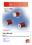
Rotary
Encoders
Linear Encoders
Motion
System
CE-65
CS-65
CK-65
• Software/Support CD: 490-01001
- Soft-No.: 490-00407
UHL00008 / UHL00005
• Additional safety instructions
• Installation
• Commissioning
• Configuration / Parameterization
• Cause of faults and remedies
TR - ECE - BA - GB - 0014 - 03
Multi-Turn
Absolute rotary encoder series Cx-65 with CAN DeviceNet™ interface
03/09/2010
User Manual
TR-Electronic GmbH
D-78647 Trossingen
Eglishalde 6
Tel.: (0049) 07425/228-0
Fax: (0049) 07425/228-33
E-mail: [email protected]
http://www.tr-electronic.de
Copyright protection
This Manual, including the illustrations contained therein, is subject to copyright
protection. Use of this Manual by third parties in contravention of copyright
regulations is forbidden. Reproduction, translation as well as electronic and
photographic archiving and modification require the written content of the
manufacturer. Offenders will be liable for damages.
Subject to amendments
Any technical changes that serve the purpose of technical progress, reserved.
Document information
Release date/Rev. date:
Document rev. no.:
File name:
Author:
03/09/2010
TR - ECE - BA - GB - 0014 - 03
TR-ECE-BA-GB-0014-03.DOC
MÜJ
Font styles
Italic or bold font styles are used for the title of a document or are used for
highlighting.
Courier font displays text, which is visible on the display or screen and software
menu selections.
″<
> ″ indicates keys on your computer keyboard (such as <RETURN>).
Trademarks
DeviceNet is a registered trademark of ODVA (Open DeviceNet Vendor Association)
© TR-Electronic GmbH 1998, All Rights Reserved
Page 2 of 31
Printed in the Federal Republic of Germany
TR - ECE - BA - GB - 0014 - 03
03/09/2010
Contents
Contents
Contents ............................................................................................................................................3
Revision index ..................................................................................................................................5
1 General information ......................................................................................................................6
1.1 Applicability......................................................................................................................6
1.2 Abbreviations used / Terminology ...................................................................................7
2 Additional safety instructions......................................................................................................8
2.1 Definition of symbols and instructions .............................................................................8
2.2 Additional instructions for proper use ..............................................................................8
2.3 Organizational measures.................................................................................................9
3 Technical data................................................................................................................................10
3.1 Electrical characteristics ..................................................................................................10
4 CAN DeviceNet information ........................................................................................................11
5 Installation / Preparation for start-up ..........................................................................................13
5.1 Connection.......................................................................................................................14
5.2 Bus termination................................................................................................................14
5.3 Identifier (MAC-ID)...........................................................................................................14
5.4 Baud rate .........................................................................................................................14
5.5 Shield cover .....................................................................................................................15
6 Commissioning..............................................................................................................................17
6.1 CAN DeviceNet interface.................................................................................................17
6.1.1 Bus status ........................................................................................................17
6.1.2 EDS file ............................................................................................................18
6.1.3 Messages ........................................................................................................18
6.1.4 Classes ............................................................................................................18
6.1.5 I/O Instance (polled IO)....................................................................................19
7 Parameterization and configuration ............................................................................................20
7.1 Configuration Assembly Data Attribute Format ...............................................................20
7.1.1 Assembly Object 04h.......................................................................................20
7.2 Parameter Object Instances ............................................................................................22
7.2.1 Parameter Object 0Fh .....................................................................................22
7.2.2 GET DATA CHECK - command ......................................................................23
7.3 Parameters / Range of values .........................................................................................23
7.3.1 Direction...........................................................................................................23
7.3.2 Output Code ....................................................................................................23
© TR-Electronic GmbH 1998, All Rights Reserved
Printed in the Federal Republic of Germany
03/09/2010
TR - ECE - BA - GB - 0014 - 03
Page 3 of 31
Contents
7.3.3 Scaling parameters..........................................................................................24
7.3.4 Adjust Absolute Value......................................................................................27
7.3.5 Auxiliary Outputs 1 - 7 .....................................................................................27
7.3.5.1 Definition of the operating- and safety-range ..................................28
8 Causes of faults and remedies ....................................................................................................29
8.1 Error and over-range messages (I/O communication port).............................................29
8.2 Parameterization errors ...................................................................................................30
8.3 Other faults ......................................................................................................................31
Appendix
Pin Assignment
Version 1.......................................................................................TR-ECE-TI-GB-0022
Version 2.......................................................................................TR-ECE-TI-GB-0030
Version 3.......................................................................................TR-ECE-TI-GB-0036
© TR-Electronic GmbH 1998, All Rights Reserved
Page 4 of 31
Printed in the Federal Republic of Germany
TR - ECE - BA - GB - 0014 - 03
03/09/2010
Revision index
Revision index
Revision
Date
Index
First release
08/06/1998
01
Documentation organized again and Pin Assignment Version 3
complemented.
12/04/1998
02
General modifications
03/09/2010
03
© TR-Electronic GmbH 1998, All Rights Reserved
Printed in the Federal Republic of Germany
03/09/2010
TR - ECE - BA - GB - 0014 - 03
Page 5 of 31
General information
1 General information
This interface-specific User Manual includes the following topics:
•
Safety instructions in additional to the basic safety instructions defined in the
Assembly Instructions
•
Electrical characteristics
•
Installation
•
Commissioning
•
Configuration / parameterization
•
Causes of faults and remedies
As the documentation is arranged in a modular structure, this User Manual is
supplementary to other documentation, such as product datasheets, dimensional
drawings, leaflets and the assembly instructions etc.
The User Manual may be included in the customer's specific delivery package or it
may be requested separately.
1.1 Applicability
This User Manual applies exclusively to the following measuring system models with
CAN DeviceNet™ interface:
•
•
•
CE-65
CS-65
CK-65
The products are labelled with affixed nameplates and are components of a system.
The following documentation therefore also applies:
•
•
•
the operator's operating instructions specific to the system,
this User Manual,
and the assembly instructions TR-ECE-BA-DGB-0046, which is enclosed
when the device is delivered
© TR-Electronic GmbH 1998, All Rights Reserved
Page 6 of 31
Printed in the Federal Republic of Germany
TR - ECE - BA - GB - 0014 - 03
03/09/2010
General information
1.2 Abbreviations used / Terminology
CAN
Controller Area Network
(manufacturer independent, open field bus standard)
CiA
CAN in Automation
(CAN User Organization, "Holding organization")
CE
Absolute Encoder with optical scanning unit,
Solid Shaft
CK
Absolute Encoder with optical scanning unit,
Integrated Claw Coupling
CS
Absolute Encoder with optical scanning unit,
Blind Shaft
DeviceNet™
CAN protocol, defined in the Application Layer (layer 7)
DUPMAC-ID-Test
DUPLICATE-MAC-ID-Test
Checking the master for duplicates of slave MAC-IDs. Each
address of the connected slaves may occur only once.
EMC
Electro Magnetic Compatibility
EDS
Electronic-Data-Sheet
MAC-ID
Media Access Control Identifier
(node address)
ODVA
Open DeviceNet Vendor Association
(CAN User Organization, especially for DeviceNet™)
© TR-Electronic GmbH 1998, All Rights Reserved
Printed in the Federal Republic of Germany
03/09/2010
TR - ECE - BA - GB - 0014 - 03
Page 7 of 31
Additional safety instructions
2 Additional safety instructions
2.1 Definition of symbols and instructions
means that death, serious injury or major damage to property
could occur if the stated precautions are not met.
WARNING!
means that minor injuries or damage to property can occur if the
stated precautions are not met.
CAUTION !
indicates important information’s or features and application tips
for the product used.
2.2 Additional instructions for proper use
The measurement system is designed for operation with CAN DeviceNet™ networks
according to the International Standard ISO/DIS 11898 and 11519-1 up to max.
500 kbit/s.
The technical guidelines for the structure of the CAN DeviceNet™ network from the
CAN User Organization ODVA are always to be observed in order to ensure safe
operation.
Proper use also includes:
•
observing all instructions in this User Manual,
•
observing the assembly instructions. The "Basic safety instructions" in
particular must be read and understood prior to commencing work.
© TR-Electronic GmbH 1998, All Rights Reserved
Page 8 of 31
Printed in the Federal Republic of Germany
TR - ECE - BA - GB - 0014 - 03
03/09/2010
Additional safety instructions
2.3 Organizational measures
•
This User Manual must always kept accessible at the site of operation of the
measurement system.
•
Prior to commencing work, personnel working with the measurement system
must have read and understood
-
the assembly instructions, in particular the chapter "Basic safety
instructions",
-
and this User Manual, in particular the chapter "Additional safety
instructions".
This particularly applies for personnel who are only deployed occasionally,
e.g. at the parameterization of the measurement system.
© TR-Electronic GmbH 1998, All Rights Reserved
Printed in the Federal Republic of Germany
03/09/2010
TR - ECE - BA - GB - 0014 - 03
Page 9 of 31
Technical data
3 Technical data
3.1 Electrical characteristics
Supply voltage................................................ 11-27 V DC, twisted in pairs and shielded
Current load.................................................... < 200 mA at 11 V DC, < 110 mA at 27 V DC (unloaded)
Total resolution .............................................. ≤ 24 bit (optional 25 bit)
Number of steps / revolution ........................ ≤ 8.192
Measurement range
Standard .................................................... ≤ 4.096 revolutions (12 bit)
Expanded .................................................. ≤ 256.000 revolutions
Baud rate (adjustable) ................................... 125 kbit/s, line length up to 500 m
250 kbit/s, line length up to 250 m
500 kbit/s, line length up to 100 m
Station addresses .......................................... 0 – 63, adjustable via DIP switches
Transmission.................................................. twisted in pairs and shielded copper cable
CAN DeviceNet interface ............................... CAN field bus interface (opto-isolated)
Data transmission...................................... CAN bus driver (ISO/DIS 11898)
Terminating resistor ...................................... 121 ohm, selectable via DIP switches
Special features.............................................. Programming of the following parameters via the
CAN-BUS:
- Direction of rotation
- Output code (binary, gray)
- Measuring length in steps
- Measuring length in revolutions
- Adjustment
- 7 special outputs
EMC
Immunity to disturbance .......................... DIN EN 61000-6-2: 2006
Transient emissions................................. DIN EN 61000-6-3: 2007
© TR-Electronic GmbH 1998, All Rights Reserved
Page 10 of 31
Printed in the Federal Republic of Germany
TR - ECE - BA - GB - 0014 - 03
03/09/2010
CAN DeviceNet information
4 CAN DeviceNet information
DeviceNet™ was developed by Rockwell Automation and the ODVA as an open field
bus standard, based on the CAN protocol and is standardized in the European
standard EN 50325. Specification and maintenance of the DeviceNet standard is
regulated by the ODVA. DeviceNet™, along with ControlNet and EtherNet/IP, belongs
to the family of CIP-based networks. The CIP (Common Industrial Protocol) forms a
common application layer for these 3 industrial networks. DeviceNet™, ControlNet and
Ethernet/IP are therefore well matched to one another and present the user with a
graduated communication system for the physical layer (Ethernet/IP), cell layer
(ControlNet) and field layer (DeviceNet™). DeviceNet™ is an object-oriented bus
system and works according to the producer/consumer model.
DeviceNet™ Protocol
The DeviceNet™ protocol is an object-oriented protocol. It is typically used for networking
sensors and actuators with the superordinate automation devices (PLC, IPC).
DeviceNet™ Data Link Layer
Layer 2 (Data Link Layer) is based on the Controller Area Network (CAN), which was
originally designed for use in motor vehicles.
DeviceNet™ Network and Data Transport Layer
The link is set up with the Group 2 Unconnected Port. Selected CAN identifiers are
used for the link set-up. A link, once set up, can be used for transmitting explicit
messages or for setting up additional I/O links. As soon as an I/O link has been set up,
I/O data can be exchanged between the DeviceNet™ users. The 11 bit identifier is
used exclusively for coding I/O data. The 8-byte wide CAN data field is fully available
for user data.
DeviceNet™ Application Layer – CIP Protocol
The CIP (Common Industrial Protocol) forms the application layer for DeviceNet™.
The CIP defines the exchange of I/O data in realtime via I/O messages (I/O
messaging or implicit messaging), as well as the exchange of data required for
configuration, diagnosis and management via explicit messages (explicit messaging).
The communication between two devices always takes place according to a
connection-oriented communication model, either via a point-to-point or a multicast-V1
connection. This allows both master/slave and multi-master systems to be realized.
Data are known as objects and are logged in the object directory of each device.
© TR-Electronic GmbH 1998, All Rights Reserved
Printed in the Federal Republic of Germany
03/09/2010
TR - ECE - BA - GB - 0014 - 03
Page 11 of 31
CAN DeviceNet information
Predefined Master-Slave Connection Set
The so-called "Predefined Master/Slave Connection Set" is used for the DeviceNet™
measuring system. This subset of the DeviceNet™ protocol simplifies the transmission
of I/O data between an automation system (PLC) and the decentralized peripheral
devices (slaves): Only "Group2 Messages" are supported, with the exception of
"Group1 Message for Slave I/O Poll Response".
DeviceNet™ Device Profiles
Beyond the specification of the pure communication functions, DeviceNet™ also
includes the definition of device profiles. These profiles define the respective device
types for minimally available objects and communication functions. The device type
number 08hex was defined for the DeviceNet™ measuring system.
Vendor ID
The vendor IDs (manufacturer’s identifiers) are assigned and administrated by the
ODVA.
The TR-Electronic vendor ID for DeviceNet™ is "134" (dec).
You can obtain further information on DeviceNet™ from the Open DeviceNet Vendor
Association (ODVA) or the following Internet addresses:
http://www.odva.org
e-mail: mailto:[email protected]
© TR-Electronic GmbH 1998, All Rights Reserved
Page 12 of 31
Printed in the Federal Republic of Germany
TR - ECE - BA - GB - 0014 - 03
03/09/2010
Installation / Preparation for start-up
5 Installation / Preparation for start-up
Up to 64 bus users can communicate with each other in a DeviceNet™ network with
Baud rates of 125, 250 or 500 kbit/s. The DeviceNet™ cable provides both signals for
CAN-L and CAN-H data transmission, as well as two lines for the 24 Volt operating
voltage supply of the DeviceNet™ bus users. The maximum length of the DeviceNet™
cable is dependent on the type of cable selected and the Baud rate. Installation takes
place in a bus topology – with or without taps – and terminators at both ends. The
terminators have a resistance value of 120 Ohm.
Bus lines
The bus lines for the DeviceNet™ system are laid down in the DeviceNet™
specification. According to this specification, the maximum extent of a DeviceNet™
system is dependent on the Baud rate:
Cable length
125 kbit/s
250 kbit/s
500 kbit/s
Total length with thick cable
500 m
250 m
100 m
Total length with thin cable
100 m
100 m
100 m
6m
6m
6m
156 m
78 m
39 m
Max. drop line length
Max. length of all drop lines
The DeviceNet™-specification and other applicable standards and guidelines
are to be observed to insure safe and stable operation.
In particular, the applicable EMC directive and the shielding and grounding
guidelines must be observed!
© TR-Electronic GmbH 1998, All Rights Reserved
Printed in the Federal Republic of Germany
03/09/2010
TR - ECE - BA - GB - 0014 - 03
Page 13 of 31
Installation / Preparation for start-up
5.1 Connection
The connection hood must first be removed from the measuring system to undertake
connection.
The pin assignments with view on the switches etc. are attached in the rear part of this
document.
For the supply shielded cables with twisted core pairs and min. 0.5 mm2 have
to be used !
5.2 Bus termination
If the measuring system is the last slave in the CAN segment, the bus is to be
terminated with the termination switch = ON. In this state, the subsequent CAN-bus is
decoupled.
5.3 Identifier (MAC-ID)
The identifier (measuring system address) 0 – 63 is adjusted via 6 DIP-switches. The
adjusted address may be assigned only once in the CAN bus.
5.4 Baud rate
The baud rate is adjusted via 2 DIP-switches.
Following baud rates are possible:
●
●
●
125 kbit/s
250 kbit/s
500 kbit/s
© TR-Electronic GmbH 1998, All Rights Reserved
Page 14 of 31
Printed in the Federal Republic of Germany
TR - ECE - BA - GB - 0014 - 03
03/09/2010
Installation / Preparation for start-up
5.5 Shield cover
The shield cover is connected with a special EMC cable gland, whereby the cable
shielding is fitted on the inside.
Cable gland assembly, variant A
Pos. 1
Pos. 2
Pos. 3
Pos. 5
1.
2.
3.
4.
5.
6.
7.
Nut
Seal
Contact bush
Screw socket
Cut shield braid / shield foil back to dimension "X".
Slide the nut (1) and seal / contact bush (2) + (3) over the cable.
Bend the shield braining / shield foil to 90° (4).
Slide seal / contact bush (2) + (3) up to the shield braining / shield foil.
Assemble screw socket (5) on the housing.
Push seal / contact bush (2) + (3) flush into the screw socket (5).
Screw the nut (1) to the screw socket (5).
© TR-Electronic GmbH 1998, All Rights Reserved
Printed in the Federal Republic of Germany
03/09/2010
TR - ECE - BA - GB - 0014 - 03
Page 15 of 31
Installation / Preparation for start-up
Cable gland assembly, variant B
Pos. 1
Pos. 2
Pos. 3
Pos. 4
Nut
Clamping ring
Inner O-ring
Screw socket
1. Cut shield braid / shield foil back to dimension "X" + 2mm.
2. Slide the nut (1) and clamping ring (2) over the cable.
3. Bend the shield braining / shield foil to approx. 90°.
4. Push clamping ring (2) up to the shield braid / shield foil and wrap the
braiding back around the clamping ring (2), such that the braiding goes
around the inner O-ring (3), and is not above the cylindrical part or the torque
supports.
5. Assemble screw socket (4) on the housing.
6. Insert the clamping ring (2) in the screw socket (4) such that the torque
supports fit in the slots in the screw socket (4).
7. Screw the nut (1) to the screw socket (4).
1
2
3
4
© TR-Electronic GmbH 1998, All Rights Reserved
Page 16 of 31
Printed in the Federal Republic of Germany
TR - ECE - BA - GB - 0014 - 03
03/09/2010
Commissioning
6 Commissioning
6.1 CAN DeviceNet interface
The CAN field bus interface (separated via optoelectronics with CAN-BUS-Driver
PCA82C250T) in the measuring system is determined according to the international
standard ISO/DIS 11898 and covers the two lower layers of the ISO/OSI reference
module.
The transformation of measuring system information into the CAN protocol occurs by
the protocol chip PCA82C200. The function of the protocol chip is monitored by a
watchdog.
The PREDEFINED MASTER/SLAVE CONNECTION SET is used for the measuring
system who only works as a slave. It will be used only the Group 2 Messages with
the exception of the Group 1 Message For Slave I/O Poll Response.
Establishing or breakdown of a connection must occur via Group 2 Only
Unconnected Explicit Request Message.
The measuring system contains an I/O Communication Port and an Explicit
Message Communication Port. The I/O communication port is used for polling the
measuring system position and must be made accessible by setting the watchdog
(after the I/O connection master/slave was set up before). Is the I/O port not
retriggered (polled) punctually the connection is interrupted and the red LED flashes.
The connection for the I/O port must be installed again.
During programming, data is exchanged between the measuring system and the
master in binary form.
6.1.1 Bus status
= ON
= OFF
= FLASHING
Measuring system is not online
- no DUP-MAC-ID test
- Device may not be powered
green
Online, with connections in the established state
- Device is allocated to a master
green
DUP-MAC-ID test successful
- No allocation to a master
red
Recoverable faults
e.g. I/O-connections are in the time-out state
- Turn off system --> turn on system
red - Replace measuring system device
© TR-Electronic GmbH 1998, All Rights Reserved
Printed in the Federal Republic of Germany
03/09/2010
TR - ECE - BA - GB - 0014 - 03
Page 17 of 31
Commissioning
6.1.2 EDS file
The EDS (electronic datasheet) contains all information on the measuring systemspecific parameters and the measuring system’s operating modes. The EDS file is
integrated using the DeviceNet™ network configuration tool to correctly configure or
operate the measuring system.
The EDS file has the file name "1.EDS". The files are on the Software/Support CD:
Order number: 490-01001, Soft-No.: 490-00407.
"3.COD" for multi-turn measuring systems with max. 4096 steps/revolution
"2.COD" for multi-turn measuring systems with max. 8192 steps/revolution
6.1.3 Messages
Following messages are supported by the measuring system:
I/O Poll Command / Respond Message
This message is sent directly by the master to the desired slave (point-to point). For
every slave which is polled the master must sent an own poll command message.
As response on a Poll Command the slave sends back to the master the Poll
Response I/O Message.
Explicit Response / Request Message
Explicit Request Messages are used for processing of WRITE/READ-attribute's.
Explicit Response Messages contains the result of an Explicit Request Message
Service.
Group 2 Only Unconnected Explicit Request Message
Group 2 Only Unconnected Explicit Request Message serves for the establishing or
breakdown of connections for the Predefined Master/Slave Connection Set.
Duplicate MAC ID Check Message
After switch-on the measuring system it reports Duplicate MAC ID Messages.
6.1.4 Classes
The communication objects are divided into classes. The measuring system supports
the following classes:
Object Class
Number of instances
01h: Identity
02h: Message Router
03h: DeviceNet
05h: Connection
04h: Assembly
0Fh: Parameter
23h: Position Sensor
1
1
1
2
2
19
1
© TR-Electronic GmbH 1998, All Rights Reserved
Page 18 of 31
Printed in the Federal Republic of Germany
TR - ECE - BA - GB - 0014 - 03
03/09/2010
Commissioning
6.1.5 I/O Instance (polled IO)
Input Instance
Number
Name
1
Position value
Input Data Format
Instance
Byte
Bit 7
Bit 6
Bit 5
Bit 4
Bit 3
Bit 2
Bit 1
Bit 0
0
D07
Low Byte Position value
D00
1
D15
.
D08
2
D23
.
D16
1
3
7. AO
6. AO
High Byte Position value
5. AO 4. AO 3. AO 2. AO
1. AO
D24
AO = Auxiliary Output
© TR-Electronic GmbH 1998, All Rights Reserved
Printed in the Federal Republic of Germany
03/09/2010
TR - ECE - BA - GB - 0014 - 03
Page 19 of 31
Parameterization and configuration
7 Parameterization and configuration
WARNING !
Danger of personal injury and damage to property exists if the measuring
system is restarted after positioning in the de-energized state by shifting of the
zero point!
If the number of revolutions is not an exponent of 2, it can occur, if more than 512
revolutions are made in the de-energized state, that the zero point of the multi-turn
measuring system is lost!
•
Ensure that the quotient of Revolutions Numerator / Revolutions Denominator for
a multi-turn measuring system is an exponent of 2 of the group
20, 21, 22…212 (1, 2, 4…4096).
or
• Ensure that every positioning in the de-energized state for a multi-turn measuring
system is within 512 revolutions.
7.1 Configuration Assembly Data Attribute Format
7.1.1 Assembly Object 04h
Instance Byte
Bit 7
Bit 6
Bit 5
0
Bit 4
Bit 3
Bit 2
Bit 1
Bit 0
Service
Direction
1
Output Code
2
Low Byte Total Number of Steps
to
5
High Byte Total Number of Steps
6
Low Byte Revolutions Numerator
to
42
9
High Byte Revolutions Numerator
10
Revolutions Denominator
11
Low Byte Lower Safety Limit
r/w
to
14
High Byte Lower Safety Limit
15
Low Byte Lower Operating Limit
to
18
High Byte Lower Operating Limit
19
Low Byte Upper Operating Limit
to
22
High Byte Upper Operating Limit
23
Low Byte Upper Safety Limit
to
26
High Byte Upper Safety Limit
Continuation, see following page
© TR-Electronic GmbH 1998, All Rights Reserved
Page 20 of 31
Printed in the Federal Republic of Germany
TR - ECE - BA - GB - 0014 - 03
03/09/2010
Parameterization and configuration
Continuation "Configuration Assembly Data Attribute Format"
Instance Byte
42
Bit 7
Bit 6
Bit 5
Bit 4
Bit 3
27
Auxiliary Output 1
28
Auxiliary Output 2
29
Auxiliary Output 3
30
Auxiliary Output 4
31
Auxiliary Output 5
32
Auxiliary Output 6
33
Auxiliary Output 7
34
0
35
0
0
0
3)
Steps/Rev. TNOS/Rev.
exceeded
=0
0
0
1)
Bit 2
Bit 0
Service
r/w
Writeerror
0
2)
Bit 1
2)
Readerror
1)
upper SL upper OL lower OL lower SL
out of
out of
out of
out of
range
range
range
range
0
While programming the parameters via the "Assembly-Class" the measuring system returns as
response at reading the programmed values with an error status in byte 34 and 35 to the
master. In this case altogether 36 bytes are transferred to the master. The Data Check is
performed automatically.
A set error bit in byte 34 or 35 is reset as soon as a parameter programming could be executed
successfully. The ranges of values of the individual parameters are defined in chapter
"Parameters / Range of values" starting from page 23.
1)
2)
3)
SL
OL
TNOS
= Safety Limit
= Operating Limit
= Total Number of Steps
© TR-Electronic GmbH 1998, All Rights Reserved
Printed in the Federal Republic of Germany
03/09/2010
TR - ECE - BA - GB - 0014 - 03
Page 21 of 31
Parameterization and configuration
7.2 Parameter Object Instances
7.2.1 Parameter Object 0Fh
Instance
Name
Data Type
1
2
3
4
5
6
7
8
9
10
11
12
13
14
15
16
17
18
19
Direction
Output Code
Total Number of Steps
Revolutions Numerator
Revolutions Denominator
Lower Safety Limit
Lower Operating Limit
Upper Operating Limit
Upper Safety Limit
Auxiliary Output 1
Auxiliary Output 2
Auxiliary Output 3
Auxiliary Output 4
Auxiliary Output 5
Auxiliary Output 6
Auxiliary Output 7
Data-Check
Read: Position / Write: Adjustment
Software version
USINT
USINT
UDINT
UDINT
USINT
UDINT
UDINT
UDINT
UDINT
USINT
USINT
USINT
USINT
USINT
USINT
USINT
UINT
UDINT
UDINT
© TR-Electronic GmbH 1998, All Rights Reserved
Page 22 of 31
Service
Attribute
r/w
r/w
r/w
r/w
r/w
r/w
r/w
r/w
r/w
r/w
r/w
r/w
r/w
r/w
r/w
r/w
r/w
r/w
ro
1
1
1
1
1
1
1
1
1
1
1
1
1
1
1
1
1
1
1
Printed in the Federal Republic of Germany
TR - ECE - BA - GB - 0014 - 03
03/09/2010
Parameterization and configuration
7.2.2 GET DATA CHECK - command
Instance 17, r/w
If the parameters are programmed via the "Parameter-Class", for taking over and test
the data, a Data-Check must be performed subsequently. The result (2 bytes) of the
SET DATA-CHECK can be read with GET DATA-CHECK. Are all bits of the returned
UINT value "0", no error is available. The possible errors are indicated in following
table:
GET DATA-CHECK:
Bit7
Bit 6
Bit 5
Bit 4
Bit 3
Bit 2
Bit 1
Bit 0
Writeerror
Readerror
Low Byte Error Receive Buffer Master
0
0
0
0
0
0
High Byte Error Receive Buffer Master
0
Steps/Rev.
exceeded
3)
1)
TNOS/Rev.
=0
upper SL
out of
range
2)
upper OL
out of
range
2)
lower OL
out of
range
1)
lower SL
out of
range
0
An error bit can only then be reset when the data is corrected and a DATA-CHECK
command is executed.
1)
2)
3)
SL
OL
TNOS
= Safety Limit
= Operating Limit
= Total Number of Steps
7.3 Parameters / Range of values
7.3.1 Direction
Instance Service Value
1
Description
=0
Position increasing clockwise
(view onto the shaft)
≠0
Position decreasing clockwise
(view onto the shaft)
r/w
Default
X
7.3.2 Output Code
Instance Service Value
2
r/w
Description
Default
=0
Binary code
X
≠0
Gray code
© TR-Electronic GmbH 1998, All Rights Reserved
Printed in the Federal Republic of Germany
03/09/2010
TR - ECE - BA - GB - 0014 - 03
Page 23 of 31
Parameterization and configuration
7.3.3 Scaling parameters
The scaling parameters can be used to change the physical resolution of the measuring
system. The measuring system supports the gearbox function for round axes.
This means that the Measuring units per revolution and the quotient of
Revolutions Numerator / Revolutions Denominator can be a decimal number. In
order that the measuring system can process this number, the measuring system
must include the option "gearbox 1/100" (see nameplate). Measuring systems
without this option may only have a decimal in the Measuring units per revolution.
The quotient of Revolutions Numerator / Revolutions Denominator must be an
exponent of 2.
The position value output is calculated with a zero point correction, the count direction
set and the gearbox parameter entered.
Total Number of Steps (Instance 3, r/w)
Defines the total number of steps of the measuring system before the measuring
system restarts at zero.
EDS-file 8192
16 steps
33554432 steps (25 bit)
33554432
lower limit
upper limit
default
EDS-file 4096
16 steps
16777216 steps (24 bit)
16777216
The actual upper limit for the Total Number of Steps to be entered is dependent on
the measuring system version and can be calculated with the formula below. As the
value "0" is already counted as a step, the end value = Total Number of Steps - 1.
Total Number of Steps = Measuring units per revolution * Number of revolutions
To calculate, the parameters Measuring units per revolution and the Number of
revolutions can be read on the measuring system nameplate.
Revolutions Numerator / Revolutions Denominator (Instance 4 and 5, r/w)
Together, these two parameters define the Number of revolutions before the
measuring system restarts at zero.
As decimal numbers are not always finite (as is e.g. 3.4), but they may have an infinite
number of digits after the decimal point (e.g. 3.43535355358774...) ) the number of
revolutions is entered as a fraction.
numerator lower limit
1
numerator upper limit
256 000
default numerator
4096
denominator lower limit
1
denominator upper limit
99
default denominator
1
© TR-Electronic GmbH 1998, All Rights Reserved
Page 24 of 31
Printed in the Federal Republic of Germany
TR - ECE - BA - GB - 0014 - 03
03/09/2010
Parameterization and configuration
Formula for gearbox calculation:
Total Number of Steps = Measuring units per revolution *
Number of Revolutions Numerator
Number of Revolutions Denominator
If it is not possible to enter parameter data in the permitted ranges of numerator and
denominator, the attempt must be made to reduce these accordingly. If this is not
possible, it may only be possible to represent the decimal number affected
approximately. The resulting minor inaccuracy accumulates for real round axis
applications (infinite applications with motion in one direction).
A solution is e.g. to perform adjustment after each revolution or to adapt the
mechanics or gearbox accordingly.
The parameter "Measuring units per revolution" may also be decimal number,
however the "Total Number of Steps" may not. The result of the above formula must
be rounded up or down. The resulting error is distributed over the total number of
revolutions programmed and is therefore negligible.
Preferably for linear axes (forward and backward motions):
The parameter "Revolutions Denominator" can be programmed as a fixed value of
"1". The parameter "Revolutions Numerator" is programmed slightly higher than the
required number of revolutions. This ensures that the measuring system does not
generate a jump in the actual value (zero transition) if the distance travelled is
exceeded. To simplify matters the complete revolution range of the measuring system
can also be programmed.
The following example serves to illustrate the approach.
Given:
-
Measuring system with 4096 steps/rev. and max. 4096 revolutions
-
Resolution 1/100 mm
-
Ensure the measuring system is programmed in its full resolution and total
measuring length (4096x4096):
Total Number of Steps
= 16777216,
Revolutions Numerator
= 4096
Revolutions Denominator = 1
Set the mechanics to be measured to the left stop position
-
Set measuring system to "0" using the adjustment
-
Set the mechanics to be measured to the end position
-
Measure the mechanical distance covered in mm
-
Read off the actual value of the measuring system from the controller
connected
© TR-Electronic GmbH 1998, All Rights Reserved
Printed in the Federal Republic of Germany
03/09/2010
TR - ECE - BA - GB - 0014 - 03
Page 25 of 31
Parameterization and configuration
Assumed:
-
Distance covered = 2000 mm
Measuring system actual position after 2000 mm = 607682 steps
Derived:
Number of revolutions covered
= 607682 steps / 4096 steps/rev.
= 148.3598633 revolutions
Number of mm / revolution = 2000 mm / 148.3598633 revs. = 13.48073499mm / rev.
For 1/100mm resolution this equates to a Measuring units per revolution of 1348.073499
Required programming:
Number of Revolutions Numerator
Number of Revolutions Denominator
= 4096
=1
Total Number of Steps = Measuring units per revolution *
= 1348,073499 steps / rev. *
Number of Revolutions Numerator
Number of Revolutions Denominator
4096 Revolutions Numerator
1 Revolutions Denominator
= 5521709 steps (rounded off)
© TR-Electronic GmbH 1998, All Rights Reserved
Page 26 of 31
Printed in the Federal Republic of Germany
TR - ECE - BA - GB - 0014 - 03
03/09/2010
Parameterization and configuration
7.3.4 Adjust Absolute Value
Risk of injury and damage to property by an actual value jump when the
adjustment function is performed!
WARNING !
• The adjustment function should only be performed when the measuring system is
at rest, otherwise the resulting actual value jump must be permitted in the
program and application!
Instance 18, r/w
With the adjustment function, the measuring system is set to the desired absolute
position value.
Is the adjustment performed via the "Parameter Class", the required position value is
set with the "SET-service" and can read as position value with the "GET-service".
After adjustment, no DATA-CHECK is necessary.
0 ≤ Adjustment < Total Number of Steps
7.3.5 Auxiliary Outputs 1 - 7
Function
Description
logical "0"
0 = error
1 = error
0 = below the operating range
1 = below the operating range
0 = in the operating range
1 = in the operating range
0 = above the operating range
1 = above the operating range
0 = below the safety range
1 = below the safety range
0 = in the safety range
1 = in the safety range
0 = above the safety range
1 = above the safety range
Output is always "0"
Output in the case of an error "0"
Output in the case of an error "1"
see chap. "7.3.5.1", page 28
"
"
"
"
"
"
"
"
"
"
"
Programming value
0
1
2
3
4
5
6
7
8
9
10
11
12
13
14
Auxiliary Output 1 - 7
Instance
lower limit
upper limit
default
10 – 16, r/w
0
14
0
© TR-Electronic GmbH 1998, All Rights Reserved
Printed in the Federal Republic of Germany
03/09/2010
TR - ECE - BA - GB - 0014 - 03
Page 27 of 31
Parameterization and configuration
7.3.5.1 Definition of the operating- and safety-range
Total capacity
Safety range
Operating range
0 = below the operating range
1 = below the operating range
0 = in the operating range
1 = in the operating range
0 = above the operating range
1 = above the operating range
0 = below the safety range
1 = below the safety range
0 = in the safety range
1 = in the safety range
0 = above the safety range
1 = above the safety range
Origin
lower
upper
Operating limit
Final value
lower
upper
Safety limit
Operating limits / Safety limits
EDS-file 8192
lower limit
upper limit
default
1
33554430
1
EDS-file 4096
1
16777214
1
© TR-Electronic GmbH 1998, All Rights Reserved
Page 28 of 31
Printed in the Federal Republic of Germany
TR - ECE - BA - GB - 0014 - 03
03/09/2010
Causes of faults and remedies
8 Causes of faults and remedies
8.1 Error and over-range messages (I/O communication port)
In order that messages can be transmitted via the I/O communication port to the master,
the auxiliary outputs 1-7 reserved there must be (see "Input Data Format", byte 3
page 19) preconfigured with the appropriate functions (see "Auxiliary Outputs 1 - 7"
page 27). To obtain the full range of messages, it is therefore advisable to distribute all
the possible functions on an auxiliary output.
Error
Cause
Remedy
Auxiliary output set
for "Error" function
- Memory area in internal
EEPROM defective
Possibly shut-off measuring system voltage then
switch on again. If the error recurs despite this
measure, the measuring system must be replaced.
Auxiliary outputs set
for the functions
"Operating range"
and "Safety range"
The switching points
programmed for the
operating and safety
range were exceeded.
These messages are not error messages, but simply
over-range messages. The use of these functions and
the associated responses to violation of the set limits
are regulated by the operator.
© TR-Electronic GmbH 1998, All Rights Reserved
Printed in the Federal Republic of Germany
03/09/2010
TR - ECE - BA - GB - 0014 - 03
Page 29 of 31
Causes of faults and remedies
8.2 Parameterization errors
If an error occurs during parameter programming or in the READ/WRITE processes of
the internal EEPROM, an error occurring can be read in two ways:
•
In "Assembly Class" programming, the measuring system automatically
returns an error status (the last two bytes), as well as the programmed values
to the master (see page 20 onwards).
•
If programming is undertaken with the "Parameter Class", an error status of 2
bytes is sent to the master (see page 22 onwards) through the GET DATACHECK command.
Low Byte
The possible errors and their avoidance are described as follows:
Bit
Description
Cause
Remedy
20 = 1
Error reading data
Memory area in the
EEPROM is defective
If the error occurs during further command execution, the
measuring system must be replaced.
21 = 1
Error writing data
Memory area in the
EEPROM is defective
If the error occurs during further command execution, the
measuring system must be replaced.
While programming the
21 = 1
Lower safety limit out
switching point, the
of range
permissible range was
exceeded
While programming the
2
2 =1
Lower operating limit
switching point, the
out of range
permissible range was
exceeded
While programming the
3
2 =1
Upper operating limit
switching point, the
out of range
permissible range was
High Byte
exceeded
While programming the
4
2 =1
Upper safety limit out
switching point, the
of range
permissible range was
exceeded
Carry out new programming
Permissible range:
1 ≤ lower safety limit ≤ lower operating limit ≤ upper
operating limit ≤ upper safety limit ≤ Total Number of
Steps -2
Carry out new programming
Permissible range:
1 ≤ lower safety limit ≤ lower operating limit ≤ upper
operating limit ≤ upper safety limit ≤ Total Number of
Steps -2
Carry out new programming
Permissible range:
1 ≤ lower safety limit ≤ lower operating limit ≤ upper
operating limit ≤ upper safety limit ≤ Total Number of
Steps -2
Carry out new programming
Permissible range:
1 ≤ lower safety limit ≤ lower operating limit ≤ upper
operating limit ≤ upper safety limit ≤ Total Number of
Steps -2
Valid range:
While programming the
5
2 =1
Revolutions
measuring length in
Numerator = 0
revolutions numerator, a "0"
was programmed.
Measuring length in revolutions numerator
1 ≤ Measuring length in revolutions numerator ≤ 256 000
Measuring length in revolutions denominator
1 ≤ Measuring length in revolutions denominator < 100
Valid range:
26 = 1
Steps per revolution
out of range
The max resolution of the
measuring system was
Total Number of Steps
≤ Hardware steps per
exceeded (see rating plate)
Number of revolutions
revolution (rating plate)
© TR-Electronic GmbH 1998, All Rights Reserved
Page 30 of 31
Printed in the Federal Republic of Germany
TR - ECE - BA - GB - 0014 - 03
03/09/2010
Causes of faults and remedies
8.3 Other faults
Fault
Cause
Remedy
Loose contacts in the
Check all the cabling and wiring used for connecting the
wiring
encoder.
Vibrations, impacts and shocks, e.g. on presses, are
Strong vibrations
dampened with "shock modules". If the error recurs despite
these measures, the measuring system must be replaced.
Position skips
of the measuring
system
Perhaps isolated flanges and couplings made of plastic
Electrical faults
EMC
help against electrical faults, as well as cables with twisted
pair wires for data and supply. Shielding and wire routing
must
be
performed
according
to
the
DeviceNet™-
specification.
Extreme axial and
radial load on the
shaft may result in a
scanning defect.
Couplings prevent mechanical stress on the shaft. If the
error still occurs despite these measures, the measuring
system must be replaced.
© TR-Electronic GmbH 1998, All Rights Reserved
Printed in the Federal Republic of Germany
03/09/2010
TR - ECE - BA - GB - 0014 - 03
Page 31 of 31