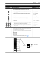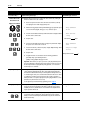
1
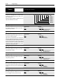
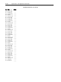
Troubleshooting
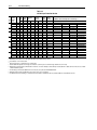
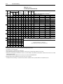
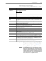
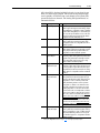
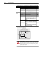
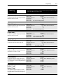
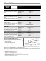
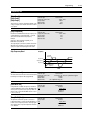
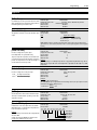
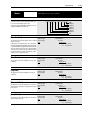
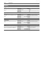
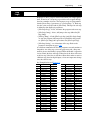
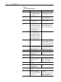
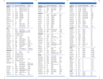
Name & Fault #
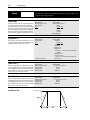
Open Pot Fault
09
Op Error Fault
11
Option Error
14
Overcurrent Flt
12
Description
An external pot is connected and
the common side of the pot is
open. The drive generates this
fault when the voltage between
pot leads is greater than 3.9V DC.
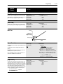
A SCANport device requests a
Read or Write of a data type not
supported. This will also occur if:
1. [Motor Type] is set to “Sync
PM” and [Stop Mode Used] is
set to “DC Brake”, or
2. [Motor Type] is set to “Sync Reluc” or “Sync PM” and [Speed
Control] is set to “Slip Comp”.
A slot A analog option board has
been installed in slot B
or
A slot B board has been installed
in slot A
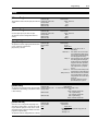
Overcurrent is detected in instantaneous overcurrent trip circuit.
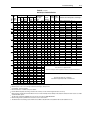
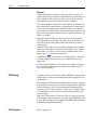
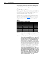
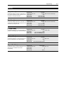
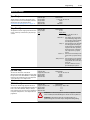
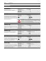
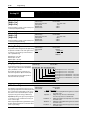
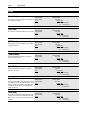
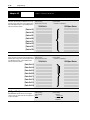
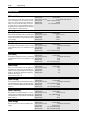
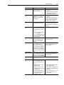
Overload Fault
07
Internal electronic overload trip.
Overspeed Fault
25
Overtemp Fault
08
Not functional at time of printing.
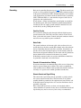
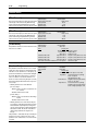
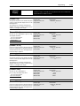
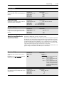
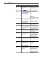
Overvolt Fault
05
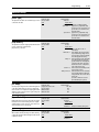
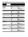
Phase U Fault
38
Phase V Fault
39
Phase W Fault
40
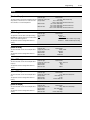
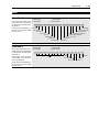
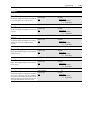
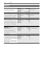
Poles Calc Flt
50
Power Loss Fault
03
Power Mode Fault
26
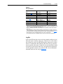
7–5
Action
Check the external potentiometer circuit at TB2 for an open circuit.
Check programming.
Remove or relocate to proper slot.
Check for a short circuit at the drive
output or excessive load conditions at
the motor.
An excessive motor load exists. It
must be reduced such that drive output current does not exceed the current set by the [Overload Amps]
parameter.
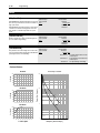
Heat sink temperature exceeds a Check for blocked or dirty heat sink
predefined value of 90° C
fins. Check that the ambient tempera(195° F).
ture has not exceeded 40° C (104° F).
Check fan.
DC bus voltage exceeded maxi- Monitor the AC line for high line voltmum value.
age or transient conditions.
Bus overvoltage can also be caused
by motor regeneration. Extend the
decel time or install dynamic brake
option.
A phase to ground fault has been Check the wiring between the drive
detected between the drive and and motor. Check motor for grounded
motor in this phase.
phase.
A phase to ground fault has been Check the wiring between the drive
detected between the drive and and motor. Check motor for grounded
motor in this phase.
phase.
A phase to ground fault has been Check the wiring between the drive
detected between the drive and and motor. Check motor for grounded
motor in this phase.
phase.
Generated if the calculated value Check [Motor NP RPM] and [Motor
of [Motor Poles] is less than 2 or NP Hertz] programming.
greater than 32.
DC bus voltage remained below Monitor the incoming AC line for low
voltage or line power interruption.
85% of nominal for longer than
500ms. [Line Loss Fault] parameter is set to “enabled.”
The internal power mode variable Check all connections to the Control
received an incorrect value.
Board. Replace the board or complete drive as required.