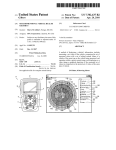
1
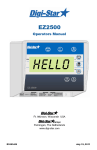
US008115489B2
(12) United States Patent
(10) Patent N0.:
(45) Date of Patent:
Pearson et al.
(54)
DETECTOR FOR DETECTING A CURRENT
CARRYING CONDUCTOR AND A METHOD
OF VALIDATING OPERATION OF THE
DETECTOR
(75) Inventors: Richard David Pearson, Bristol (GB);
Kevin Conway, Newport (GB)
(73) Assignee: Radiodetection Limited, Bristol (GB)
(*)
Notice:
Subject to any disclaimer, the term of this
patent is extended or adjusted under 35
U.S.C. 154(b) by 295 days.
7,403,012 B2 *
7,847,556 B2 *
7,969,137 B2 *
7/2008
12/2010
6/2011
US 8,115,489 B2
Feb. 14, 2012
Worsley et al. ............. .. 324/326
Royle .......... ..
324/326
Royle ....... ..
324/329
7,994,770 B2 *
8/2011
Royle et a1. .
324/329
2003/0058961 A1*
3/2003
Fling et al. ....... ..
375/316
2006/0284610 A1* 12/2006 Thompson et al.
2006/0284616 A1* 12/2006 Pearson et al.
2007/0290672
A1 *
2009/0243583 A1*
2010/0001712
2010/0001713
2010/0001714
2010/0001731
2010/0001732
A1*
A1*
A1*
A1*
A1*
2010/0004880 A1*
12/2007
Worsley et al.
....
324/67
324/326
. . . ..
10/2009 Olsson et al. ..
324/67
324/67
1/2010 Royle et a1.
324/67
1/2010
Royle
. . . . . . . . .
. . . ..
324/67
1/2010
Royle
. . . . . . . . .
. . . ..
324/67
1/2010
Royle et a1. .
1/2010 Royle et a1.
1/2010
.. 324/326
324/326
Royle et a1. ................. .. 324/326
FOREIGN PATENT DOCUMENTS
(21) App1.No.: 12/395,838
(22) Filed:
Mar. 2, 2009
(65)
Prior Publication Data
US 2010/0060285 A1
(30)
(51)
(GB) ................................. .. 08038739
Int. Cl.
G01V3/08
(2006.01)
(52)
Us. or. ..................................................... .. 324/326
(58)
Field of Classi?cation Search ...................... .. None
See application ?le for complete search history.
(56)
References Cited
202004006336
0036257
0735377
2349841
2006-275959
U1
A1
A2
A1
A
8/2004
9/1981
3/1996
12/1977
10/2006
OTHER PUBLICATIONS
Mar. 11, 2010
Foreign Application Priority Data
Feb. 29, 2008
DE
EP
EP
FR
JP
“RD4000 Locating System User Manual, Rev 3,” Radiodetection
Limited, Oct. 2002.
* cited by examiner
Primary Examiner * Jer'mele M Hollington
(74) Attorney, Agent, or Firm * Baker & Hostetler LLP
(57)
ABSTRACT
A detector for detecting a buried conductor comprises a plu
rality of antennas B, T. Each antenna B, T has a Winding
Wound around the antenna, the Winding being connected to a
current source for providing a prede?ned current in the Wind
U.S. PATENT DOCUMENTS
4,387,340 A
5,043,666 A
5,541,516 A
6/1983 Peterman
8/1991 Tavernettiet a1.
7/1996 Rideret a1.
6,728,662 B2*
7,091,872 B1*
4/2004
8/2006
Frost et a1. .................... .. 324/66
Bigelow et a1. ............. .. 340/664
7,336,078 B1
2/2008 Merewether et a1.
7,342,537 B2*
3/2008
Pearson et a1. .............. .. 342/459
ing. When the prede?ned current is applied to the Winding an
electromagnetic ?eld is generated at the antenna Which
induces a test current in the antenna. The test current is com
pared to calibration data stored in the detector to validate the
correct operation of the detector.
20 Claims, 2 Drawing Sheets
US. Patent
Feb. 14, 2012
Sheet 1 012
US 8,115,489 B2
Receiver
Transmitter
Figure 1
23
5\
PSU
1
// 3
Antennas
1
I // 5
S|gna|
Processor
Controller
I
ul/
Figure 2
2
/
—|_
/
//—j—Comms
/-19
/' 21
Memory
US. Patent
Feb. 14, 2012
Figure 3
Sheet 2 M2
“/r31
US 8,115,489 B2
s
27\
Figure 4
US 8,115,489 B2
1
2
DETECTOR FOR DETECTING A CURRENT
CARRYING CONDUCTOR AND A METHOD
OF VALIDATING OPERATION OF THE
DETECTOR
The processor may be con?gured to store results of the test
in the memory.
The detector may further comprise a user interface for
conveying the results of the test to a user and a communica
tions module for transmitting results of the test to another
device.
According to a second aspect of the invention there is
provided a system for validating the operation of a detector as
CROSS REFERENCE TO RELATED
APPLICATIONS
This application claims priority to United Kingdom Patent
Application GB 0803873.9, ?led on Feb. 29, 2008, and
entitled “A Detector for Detecting a Current Carrying Con
ductor and a Method ofValidating Operation of the Detector,”
the disclosure of Which is incorporated herein by reference in
de?ned above, the system comprising: a microprocessor-con
trolled device having a communications module for commu
nicating With the communications module of said detector
and a communications module for accessing a netWork,
Wherein the device is con?gured to receive test results from
said detector and transmit the test results to said netWork.
The system may further comprise a server connected to
said netWork, Wherein the server is con?gured to receive test
its entirety.
FIELD OF THE INVENTION
The present invention relates to a detector for detecting a
current carrying conductor and a method of validating opera
tion of the detector.
results from the microprocessor-controlled device. The
server may be con?gured to generate a calibration certi?cate
20
if the test results indicate that said detector is operating Within
predetermined limits, the calibration certi?cate being doWn
BACKGROUND OF THE INVENTION
Before commencing excavation or other Work Where elec
trical cables, ?bre optic cables or other utilities ducts or pipes
are buried, it is important to determine the location of such
25
comprising: providing a prede?ned current in the Winding to
generate an electromagnetic ?eld at each antenna, thereby
buried cables or pipes to ensure that they are not damaged
during the Work.
Current carrying conductors emit electromagnetic radia
inducing a test current in each antenna; and processing the test
tion Which can be detected by an electrical antenna. If ?bre
optic cables or non-metallic utilities ducts or pipes are ?tted
With a small electrical tracer line, an alternating electrical
current can be induced in the tracer line Which in turn radiates
electromagnetic radiation. It is knoWn to use detectors to
30
detect the electromagnetic ?eld emitted by conductors carry
35
currents to determine if the test currents are Within predeter
mined limits of the calibration data.
The predetermined limits for each antenna may be the
ing alternating current.
Once a buried utility is located the depth of the utility can
be calculated to determine a safe excavation depth. It is
calibration data 10.01%. The processor may disable the
detector if one of the test currents is outside the predetermined
limits of the calibration data.
The plurality of antennas may comprise tWo or three par
allel antennas Which in use are oriented horizontally and
spaced vertically.
The processor may store results of the test in the memory
important that the depth information provided to the operator
is accurate so as to avoid damage to the buried utility or injury
to person When excavating the area.
loadable from the server to the microprocessor-controlled
device. The netWork may be the Internet.
According to a third aspect of the invention there is pro
vided a method of validating the operation of a detector for
detecting a buried conductor as de?ned above, the method
40
and the test may be conveyed to a user via a user interface.
The method may further comprise: providing the detector
With a communications module; providing a microprocessor
SUMMARY OF THE INVENTION
controlled device having a communications module for com
municating With the communications module of the detector;
Embodiments of the present invention advantageously pro
45
and transmitting the results of the test from the detector to the
vide a detector for detecting a current carrying conductor and
microprocessor-controlled device via the communications
a method of validating operation of the detector.
According to a ?rst aspect of the invention there is provided
modules.
a detector for detecting a buried conductor, the detector com
processor-controlled device With a communications module
for accessing a netWork; and transmitting results of the test
from the microprocessor-controlled device to said netWork.
The method may further comprise: providing a server con
nected to said netWork; and transmitting results of the test
The method may further comprise: providing the micro
prising: a plurality of antennas for detecting an electromag
netic ?eld; a plurality of Windings, each Wound around a
respective antenna, each Winding being connected to a cur
rent source for providing a prede?ned current in the Winding
to generate an electromagnetic ?eld at the antenna, thereby
50
inducing a test current in the antenna; a memory for storing
calibration data of the antennas; and a processor con?gured to
process the test currents in the antennas to determine if the test
currents are Within predetermined limits of the calibration
data.
The predetermined limits for each antenna may be the
calibration data 10.01%.
The processor may be con?gured to disable the detector if
one of the test currents is outside the predetermined limits of
the calibration data.
The plurality of antennas may comprise tWo or three par
allel antennas Which in use are oriented horizontally and
55
spaced vertically.
from the microprocessor-controlled device to the server over
said netWork.
The method may further comprise: generating a calibration
certi?cate at the server if the test results indicate that the
detector is operating Within predetermined limits and doWn
loading the calibration certi?cate from the server to the
60
microprocessor-controlled device. The netWork may be the
Internet.
The detector described above may further comprise a hous
ing in Which the other components of the detector are housed,
Wherein the detector is portable.
65
According to a further aspect of the invention there is
provided a system for detecting a buried conductor compris
ing: a transmitter for generating an alternating current test
US 8,115,489 B2
3
4
signal in said conductor; and a detector as de?ned above for
signal representative of the electromagnetic ?eld 11 at the
detecting the signal generated in said buried conductor by the
antenna. The outputs from the antenna module 13 are fed into
transmitter.
a signal processor module 15 for isolating signals of a desired
frequency band or bands and processing these signals to
There has thus been outlined, rather broadly, certain
embodiments of the invention in order that the detailed
derive their characteristics using knoWn techniques. The sig
description thereof herein may be better understood, and in
nal processor module 15 may comprise a pre-ampli?cation
order that the present contribution to the art may be better
appreciated. There are, of course, additional embodiments of
the invention that Will be described beloW and Which Will
antennas if the detected signal is Weak. The signal processor
module 15 may further comprise an analogue to digital con
stage for amplifying the ?eld strength signals output from the
form the subject matter of the claims appended hereto.
ver‘ter for converting the ?eld strength signals into digital
signals and a digital signal processor for processing the digi
tised signals.
In this respect, before explaining at least one embodiment
of the invention in detail, it is to be understood that the
invention is not limited in its application to the details of
construction and to the arrangements of the components set
forth in the folloWing description or illustrated in the draW
ings. The invention is capable of embodiments in addition to
those described and of being practiced and carried out in
various Ways. Also, it is to be understood that the phraseology
and terminology employed herein, as Well as the abstract, are
for the purpose of description and should not be regarded as
The receiver comprises a communications module 17 to
provide a communication/data link betWeen the receiver 5
and a microprocessor-controlled device such as a personal
computer (PC) or a personal digital assistant (PDA) (not
20
limiting.
As such, those skilled in the art Will appreciate that the
conception upon Which this disclosure is based may readily
be utiliZed as a basis for the designing of other structures,
methods and systems for carrying out the several purposes of
the present invention. It is important, therefore, that the
claims be regarded as including such equivalent constructions
insofar as they do not depart from the spirit and scope of the
present invention.
25
screen and an audible output device such as a speaker or
beeper. The receiver 5 further comprises a memory module 21
and a poWer supply unit (PSU) 23 comprising poWer man
agement circuitry and a poWer source such as batteries. The
30
BRIEF DESCRIPTION OF THE DRAWINGS
FIG. 1 is a schematic representation of a detector system
for detecting a buried conductor according to an embodiment
of the invention.
FIG. 2 is a block diagram of the detector of the system of
FIG. 1.
FIG. 3 is a representation of tWo antennas of the detector of
FIG. 2.
FIG. 4 shoWs a system for validating operation of the
When the receiver is located over a current carrying con
35
40
45
draWing ?gures, in Which like reference numerals refer to like
antennas B, T. In use the detector 5 is held vertical on ground
27 in Which a current carrying conductor 7 is buried, With the
bottom antenna B close to the surface of the ground 27. The
axes of the antennas are parallel and the separation betWeen
the bottom antenna B and the top antenna T is 2s. The con
ductor 7 is buried at a depth d beloW the surface of the ground
27 (and beloW the bottom antenna B) and the horiZontal
displacement betWeen the antennas B and T and the conduc
tor 7 is x. The components of the portable detector 5 are
housed in a housing (not shoWn).
parts throughout.
table receiver/ detector 5. The transmitter 3 is placed in prox
imity to a buried conductor 7 to produce an alternating current
test signal in the buried conductor 7.
An aerial in the transmitter 3 is fed With an AC voltage to
produce an electromagnetic ?eld 9 Which links With the bur
comparing the current induced in at least tWo of the antennas
in the antenna module 13. FIG. 3 shoWs an antenna module 13
of a detector 5 comprising tWo horiZontal vertically spaced
DETAILED DESCRIPTION
FIG. 1 is a schematic representation of a system 1 for
detecting a buried conductor according to an embodiment of
the invention, comprising a portable transmitter 3 and a por
overall control of the various components of the receiver 5 is
managed by a controller 25.
ductor Which radiates an electromagnetic ?eld, the depth of
the conductor can be calculated using knoWn techniques by
detector of FIG. 2.
The invention Will noW be described With reference to the
shoWn). The communication link may be implemented via a
Wired or Wireless connection. Additionally the communica
tions module 17 may provide a communication link With the
transmitter 3.
A user interface module 19 is provided to convey informa
tion to the operator of the receiver 5 and may comprise one or
more of a display for displaying information to the operator of
the device, input devices such as a keypad or a touch sensitive
50
When an alternating current ?oWs in the conductor 7 and
the conductor 7 radiates an electromagnetic ?eld, the mag
netic ?ux density or magnetic ?eld at the bottom antenna B is
BB and the magnetic ?ux density at the top antenna T is B T.
The depth of the buried conductor 7 beloW the surface 27 of
the ground is given by:
55
ied conductor 7, thereby inducing the alternating current test
signal in the buried conductor 7. The alternating current test
signal is radiated as an electromagnetic ?eld 11 by the buried
conductor 7 and this electromagnetic ?eld can be detected by
the receiver 5. In other embodiments the transmitter may
provide a test signal in the conductor by direct connection to
the conductor or by clamping around the conductor, as is
60
knoWn in the art.
FIG. 2 is a block diagram of the receiver 5 of the system 1
of FIG. 1. An electromagnetic ?eld 11 radiated by the buried
conductor 7 is detected by a plurality of antennas in an
antenna module 13. Each antenna outputs a ?eld strength
65
It can be seen from the above equation that in order to
produce an accurate depth calculation the outputs from the
bottom antenna B and the top antenna T must be correctly
calibrated With respect to each other. The calibration of the
top antenna T relative to the bottom antenna B is performed
When the detector is set up after manufacture and factory
calibration data is stored in the memory 21. This invention
provides a detector Which can perform a self-test to ensure
US 8,115,489 B2
5
6
that the calibration of the antennas is Within acceptable limits
and a method of validating the operation of the detector.
In the detector 5 of FIGS. 2 and 3 each antenna B, T is
person skilled in the art that the detector may comprise three
parallel horiZontal antennas or more and that some or all of
the antennas may comprise a Winding Wound around the
provided With a Winding 29 (shoWn in dotted lines) Which is
ferrite of the antenna and connected to a precision current
source to provide an integrated built-in test capability for
Wound around the ferrite of the antenna and connected to a
precision current source 31 (shoWn in dotted lines) to provide
an integrated built-in test capability. After the relative cali
some or all of the antennas.
Aspects of the present invention canbe implemented in any
convenient form, for example using dedicated hardWare, or a
mixture of dedicated hardWare and softWare. The processing
apparatuses can comprise any suitably programmed appara
tuses such as a general purpose computer, personal digital
assistant, mobile telephone (such as a WAP or 3G-compliant
bration of the top antenna T and the bottom antenna B is
performed in the factory, separate calibration data is gener
ated in the factory for the top antenna T and for the bottom
antenna B by using the precision current source 31 of each
antenna to generate a known, prede?ned current in the Wind
ing 29 and recording the current induced in the antennas B, T.
This calibration data is stored in the memory 21 of the detec
phone) and so on. Since the present invention can be imple
mented as softWare, each and every aspect of the present
tor 5 so that it is available for future calibration self-tests.
invention thus encompasses computer softWare implement
If it is desired to check that the detector 5 is still performing
Within its calibration limits then the user initiates the calibra
be provided to the programmable device using any conven
able on a programmable device. The computer softWare can
tion procedure through the user interface 19. The prede?ned
tional carrier medium. The carrier medium can comprise a
transient carrier medium such as an electrical, optical, micro
test current is generated by the precision current sources 31
and passed through the Windings 29 to produce electromag
20
netic ?elds at the antennas B, T Which induces test currents in
the respective antennas B, T. The test currents output from the
antennas B, T are compared to the factory calibration data
stored in the memory 21 for each antenna B, T to verify that
the currents are Within predetermined limits of the factory
calibration data. If the currents output from both of the anten
nas B, T are Within the predetermined limits then the calibra
tion test is deemed to be a pass. The predetermined limit for
each antenna is that the test current is Within the factory
calibration data 10.01% (i.e., 1 part in 10,000). If the current
output from one of the antennas B, T is not Within the prede
termined limits then the calibration test is deemed to be a fail.
The results of the integrated built-in test are conveyed to the
TCP/IP signal carrying computer code over an IP netWork,
such as the lntemet. The carrier medium can also comprise a
storage medium for storing processor readable code such as a
25
apparent from the detailed speci?cation, and, thus, it is
30
35
40
?eld,
a plurality of Windings, each Wound around a respective
antenna, each Winding being connected to a current
45
The PC 33 and PDA 35 are connected or connectable via a
netWork 37, such as the lntemet, to a server 39. The server 39
source for providing a prede?ned current in the Wind
ing to generate an electromagnetic ?eld at the
antenna, thereby inducing a test current in the
antenna,
a memory for storing calibration data of the antennas,
50
The results of the calibration test together With an identi?er
of the detector 5, such as a serial number, can be uploaded
from the memory 21 of the detector 5 to the PC 33 or PDA 35
a processor con?gured to process the test currents in the
antennas to determine if the test currents are Within
predetermined limits of the calibration data, and
and from there via the netWork 37 to a server 39 so that the
55
a communications module for transmitting calibration
test results; and
a microprocessor-controlled device for receiving the cali
bration test results from the detector.
2. The system according to claim 1, Wherein the predeter
mined limits for each antenna are the calibration data 10.01%.
3. The system according to claim 1, Wherein the processor
a test pass certi?cate Which can be doWnloaded to the PC 33
or PDA 35. A printer 43 connected to the PC 33 can print the
calibration certi?cate to shoW that the detector 5 passed the
calibration test on the date in question.
Various modi?cations Will be apparent to those in the art
and it is desired to include all such modi?cations as fall Within
60
the scope of the accompanying claims.
For example, the detector 5 shoWn in the Figures comprises
65
tWo parallel horiZontal antennas. It Will be understood by a
1. A system for detecting a buried conductor, comprising:
a detector, including:
a plurality of antennas for detecting an electromagnetic
embodiments the detector 5 may communicate via a Wired
connection.
results can be stored in the memory 41 associated With the
server 39 to record the test results and Whether the detector 5
passed or failed the calibration test on the date in question. If
the calibration test Was passed then the server 39 can generate
and, accordingly, all suitable modi?cations and equivalents
We claim:
PC 33, a PDA 35 or other microprocessor-controlled device
can access a storage device 41.
intended by the appended claims to cover all such features
and advantages of the invention Which fall Within the true
spirit and scope of the invention. Further, since numerous
modi?cations and variations Will readily occur to those
skilled in the art, it is not desired to limit the invention to the
exact construction and operation illustrated and described,
may be resorted to that fall Within the scope of the invention.
munications module 17 With a communications module of a
(not shoWn). In the system of FIG. 4 the detector 5 commu
nicates Wirelessly With the PC 33 and PDA 35 but in other
?oppy disk, hard disk, CD ROM, magnetic tape device or
solid state memory device.
The many features and advantages of the invention are
user by means of the user interface 19 and stored in the
memory 21. If the detector 5 fails the integrated built-in test
then a Warning is displayed to indicate that the detector 5 is
out of calibration. Alternatively or additionally the controller
25 may lock the detector 5 to prevent its use until the detector
is recalibrated and the integrated built-in test is passed.
FIG. 4 shoWs a system for validating the operation of the
detector of FIG. 2. The detector 5 communicates via its com
Wave, acoustic or radio frequency signal carrying the com
puter code. An example of such a transient medium is a
is con?gured to disable the detector if one of the test currents
is outside the predetermined limits of the calibration data.
4. The system according to claim 1, Wherein the plurality of
antennas comprise tWo parallel antennas Which in use are
oriented horiZontally and spaced vertically.
5. The system according to claim 1, Wherein the plurality of
antennas comprise three parallel antennas Which in use are
oriented horiZontally and spaced vertically.
US 8,115,489 B2
8
7
6. The system according to claim 1, wherein the processor
transmitting calibration test results from the detector to a
is con?gured to store results of the test in the memory.
microprocessor-controlled device.
7. The system according to claim 1, Wherein the detector
13. The method according to claim 12, Wherein the prede
further comprises a user interface for conveying the calibra
termined limits for each antenna are the calibration data
10.01%.
tion test results to a user.
8. The system according to claim 1, further comprising:
14. The method according to claim 12, further comprising
a transmitter for generating an alternating current test sig
nal in said conductor.
disabling the detector if one of the test currents is outside the
predetermined limits of the calibration data.
15. The method according to claim 12, Wherein the plural
ity of antennas comprise tWo parallel antennas Which in use
are oriented horiZontally and spaced vertically.
16. The method according to claim 12, further comprising
storing the calibration test results in the memory.
17. The method according to claim 12, further comprising
9. The system according to claim 1, further comprising a
server connected to a netWork, Wherein the microprocessor
controlled device transmits the calibration test results to the
server over the network.
10. The system according to claim 9, Wherein the server is
con?gured to generate a calibration certi?cate if the test
results indicate that said detector is operating Within prede
termined limits.
11. The system according to claim 10, Wherein the calibra
conveying the calibration test results to a user via a user
tion certi?cate is doWnloadable from the server to the micro
18. The method according to claim 12, further comprising:
transmitting the calibration test results from the micropro
interface.
processor-controlled device.
12. A method of validating the operation of a detector for
detecting a buried conductor, the detector including a plural
ity of antennas, a plurality of Windings, each Winding Wound
20
generating a calibration certi?cate at the server if the cali
around a respective antenna and connected to a current
source, a memory, a processor and a communications mod
bration test results indicate that the detector is operating
ule, the method comprising:
providing a prede?ned current in the Winding to generate
an electromagnetic ?eld at each antenna, thereby induc
ing a test current in each antenna;
processing the test currents to determine if the test currents
are Within predetermined limits of the calibration data;
and
cessor-controlled device to a server over a netWork.
19. The method according to claim 18, further comprising:
25
Within predetermined limits.
20. The method according to claim 19, further comprising:
doWnloading the calibration certi?cate from the server to
the microprocessor-controlled device.