1
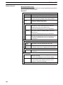
Cat.No. V064–E1–1
NT31, NT31C, NT631 and NT631C
Programmable Terminals
REFERENCE MANUAL
NT31, NT31C, NT631, and NT631C
Programmable Terminals
Reference Manual
Produced July 2000
Notice:
OMRON products are manufactured for use according to proper procedures by a qualified operator
and only for the purposes described in this manual.
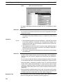
The following conventions are used to indicate and classify precautions in this manual. Always heed
the information provided with them. Failure to heed precautions can result in injury to people or damage to property.
DANGER
Indicates an imminently hazardous situation which, if not avoided, will result in death or
serious injury.
! WARNING
Indicates a potentially hazardous situation which, if not avoided, could result in death or
serious injury.
! Caution
Indicates a potentially hazardous situation which, if not avoided, may result in minor or
moderate injury, or property damage.
!
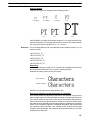
OMRON Product References
All OMRON products are capitalized in this manual. The word “Unit” is also capitalized when it refers
to an OMRON product, regardless of whether or not it appears in the proper name of the product.
The abbreviation “Ch,” which appears in some displays and on some OMRON products, often means
“word” and is abbreviated “Wd” in documentation in this sense.
The abbreviation “PC” means Programmable Controller and is not used as an abbreviation for anything else.
Visual Aids
The following headings appear in the left column of the manual to help you locate different types of
information.
Note Indicates information of particular interest for efficient and convenient operation
of the product.
1, 2, 3...
1. Indicates lists of one sort or another, such as procedures, checklists, etc.
OMRON, 2000
All rights reserved. No part of this publication may be reproduced, stored in a retrieval system, or transmitted, in any
form, or by any means, mechanical, electronic, photocopying, recording, or otherwise, without the prior written permission of OMRON.
No patent liability is assumed with respect to the use of the information contained herein. Moreover, because OMRON is
constantly striving to improve its high-quality products, the information contained in this manual is subject to change
without notice. Every precaution has been taken in the preparation of this manual. Nevertheless, OMRON assumes no
responsibility for errors or omissions. Neither is any liability assumed for damages resulting from the use of the information contained in this publication.
v
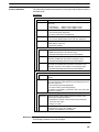
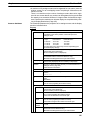
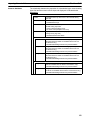
TABLE OF CONTENTS
SECTION 1
General . . . . . . . . . . . . . . . . . . . . . . . . . . . . . . . . . . . . . . . .
1-1
1-2
1-3
1-4
1-5
1-6
Role and Operation of the PT . . . . . . . . . . . . . . . . . . . . . . . . . . . . . . . . . . . . . . . . . . . . . .
Functions of the NT31/NT31C and NT631/NT631C . . . . . . . . . . . . . . . . . . . . . . . . . . . .
System Configuration . . . . . . . . . . . . . . . . . . . . . . . . . . . . . . . . . . . . . . . . . . . . . . . . . . . . .
Communications with the Host . . . . . . . . . . . . . . . . . . . . . . . . . . . . . . . . . . . . . . . . . . . . .
Communication by Using Memory Link . . . . . . . . . . . . . . . . . . . . . . . . . . . . . . . . . . . . . .
Before Operating . . . . . . . . . . . . . . . . . . . . . . . . . . . . . . . . . . . . . . . . . . . . . . . . . . . . . . . .
SECTION 2
PT Functions . . . . . . . . . . . . . . . . . . . . . . . . . . . . . . . . . . .
2-1
2-2
2-3
2-4
2-5
2-6
2-7
2-8
2-9
2-10
2-11
2-12
2-13
2-14
2-15
2-16
2-17
2-18
2-19
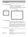
PT Screens . . . . . . . . . . . . . . . . . . . . . . . . . . . . . . . . . . . . . . . . . . . . . . . . . . . . . . . . . . . . .
Areas for Control/Notification . . . . . . . . . . . . . . . . . . . . . . . . . . . . . . . . . . . . . . . . . . . . . .
Memory Tables . . . . . . . . . . . . . . . . . . . . . . . . . . . . . . . . . . . . . . . . . . . . . . . . . . . . . . . . . .
Fixed Displays . . . . . . . . . . . . . . . . . . . . . . . . . . . . . . . . . . . . . . . . . . . . . . . . . . . . . . . . . .
Image and Library Data . . . . . . . . . . . . . . . . . . . . . . . . . . . . . . . . . . . . . . . . . . . . . . . . . . .
Lamps . . . . . . . . . . . . . . . . . . . . . . . . . . . . . . . . . . . . . . . . . . . . . . . . . . . . . . . . . . . . . . . . .
Touch Switches . . . . . . . . . . . . . . . . . . . . . . . . . . . . . . . . . . . . . . . . . . . . . . . . . . . . . . . . . .
Numeral Display . . . . . . . . . . . . . . . . . . . . . . . . . . . . . . . . . . . . . . . . . . . . . . . . . . . . . . . .
Character String Display . . . . . . . . . . . . . . . . . . . . . . . . . . . . . . . . . . . . . . . . . . . . . . . . . .
Graphs . . . . . . . . . . . . . . . . . . . . . . . . . . . . . . . . . . . . . . . . . . . . . . . . . . . . . . . . . . . . . . . . .
Alarm List, Alarm History . . . . . . . . . . . . . . . . . . . . . . . . . . . . . . . . . . . . . . . . . . . . . . . . .
Inputting Numeric Values . . . . . . . . . . . . . . . . . . . . . . . . . . . . . . . . . . . . . . . . . . . . . . . . .
Inputting Character Strings . . . . . . . . . . . . . . . . . . . . . . . . . . . . . . . . . . . . . . . . . . . . . . . .
Recipe . . . . . . . . . . . . . . . . . . . . . . . . . . . . . . . . . . . . . . . . . . . . . . . . . . . . . . . . . . . . . . . . .
Window Function . . . . . . . . . . . . . . . . . . . . . . . . . . . . . . . . . . . . . . . . . . . . . . . . . . . . . . . .
Special Functions . . . . . . . . . . . . . . . . . . . . . . . . . . . . . . . . . . . . . . . . . . . . . . . . . . . . . . . .
Device Monitor Function . . . . . . . . . . . . . . . . . . . . . . . . . . . . . . . . . . . . . . . . . . . . . . . . . .
Mathematical Function . . . . . . . . . . . . . . . . . . . . . . . . . . . . . . . . . . . . . . . . . . . . . . . . . . .
PT Configuration Settings . . . . . . . . . . . . . . . . . . . . . . . . . . . . . . . . . . . . . . . . . . . . . . . . .
SECTION 3
How to Use the PT . . . . . . . . . . . . . . . . . . . . . . . . . . . . . . .
3-1
3-2
3-3
3-4
3-5
3-6
3-7
3-8
3-9
3-10
3-11
3-12
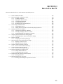
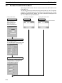
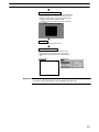
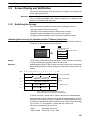
Screen Creation Procedure . . . . . . . . . . . . . . . . . . . . . . . . . . . . . . . . . . . . . . . . . . . . . . . . .
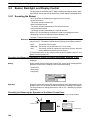
Buzzer, Backlight, and Display Control . . . . . . . . . . . . . . . . . . . . . . . . . . . . . . . . . . . . . .
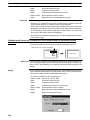
Screen Display and Notification . . . . . . . . . . . . . . . . . . . . . . . . . . . . . . . . . . . . . . . . . . . .
Display and Control of Windows . . . . . . . . . . . . . . . . . . . . . . . . . . . . . . . . . . . . . . . . . . . .
Changing Numeral and Character String Display . . . . . . . . . . . . . . . . . . . . . . . . . . . . . . .
Display of Graphs . . . . . . . . . . . . . . . . . . . . . . . . . . . . . . . . . . . . . . . . . . . . . . . . . . . . . . . .
Input of Numeric Values and Character Strings . . . . . . . . . . . . . . . . . . . . . . . . . . . . . . . .
Using the Alarm List/History Function . . . . . . . . . . . . . . . . . . . . . . . . . . . . . . . . . . . . . . .
Using the Display History Function . . . . . . . . . . . . . . . . . . . . . . . . . . . . . . . . . . . . . . . . . .
Display and Setting of Calendar Clock . . . . . . . . . . . . . . . . . . . . . . . . . . . . . . . . . . . . . . .
Printing Data and Checking the Printer Status . . . . . . . . . . . . . . . . . . . . . . . . . . . . . . . . .
Enabling/Disabling PT Operations . . . . . . . . . . . . . . . . . . . . . . . . . . . . . . . . . . . . . . . . . .
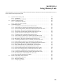
SECTION 4
Using Memory Link . . . . . . . . . . . . . . . . . . . . . . . . . . . . . .
4-1
4-2
4-3
4-4
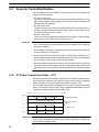
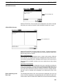
Operation of the Memory Link . . . . . . . . . . . . . . . . . . . . . . . . . . . . . . . . . . . . . . . . . . . . .
Outline of Communications . . . . . . . . . . . . . . . . . . . . . . . . . . . . . . . . . . . . . . . . . . . . . . . .
Commands/Responses . . . . . . . . . . . . . . . . . . . . . . . . . . . . . . . . . . . . . . . . . . . . . . . . . . . .
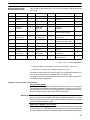
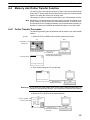
Memory Link Online Transfer Function . . . . . . . . . . . . . . . . . . . . . . . . . . . . . . . . . . . . . .
1
2
4
18
21
29
31
33
35
46
64
81
97
103
110
130
138
144
173
183
201
207
228
235
250
269
275
277
278
280
289
298
306
317
318
337
342
345
352
355
359
360
362
365
387
vii
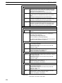
TABLE OF CONTENTS
SECTION 5
Function Applications . . . . . . . . . . . . . . . . . . . . . . . . . . . .
5-1
5-2
Examples of Actual Applications of Direct Access . . . . . . . . . . . . . . . . . . . . . . . . . . . . .
Examples of Actual Applications of Memory Link . . . . . . . . . . . . . . . . . . . . . . . . . . . . .
SECTION 6
Troubleshooting and Maintenance . . . . . . . . . . . . . . . . . .
6-1
6-2
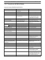
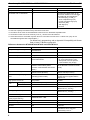
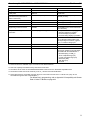
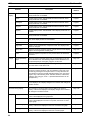
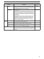
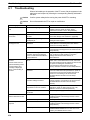
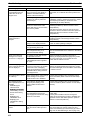
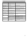
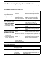
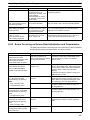
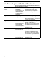
Troubleshooting . . . . . . . . . . . . . . . . . . . . . . . . . . . . . . . . . . . . . . . . . . . . . . . . . . . . . . . . .
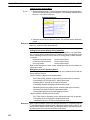
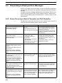
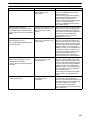
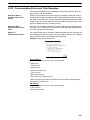
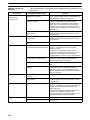
Responding to Displayed Error Messages . . . . . . . . . . . . . . . . . . . . . . . . . . . . . . . . . . . . .
391
392
405
409
410
414
Appendices
A
B
C
D
E
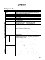
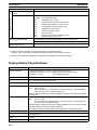
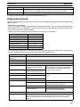
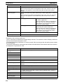
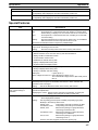
Specifications . . . . . . . . . . . . . . . . . . . . . . . . . . . . . . . . . . . . . . . . . . . . . . . . . . . . . . . . . . . . .
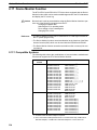
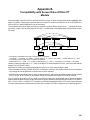
Compatibility with Screen Data of Other PT Models . . . . . . . . . . . . . . . . . . . . . . . . . . . . . .
NT30/620 Compatible Mode . . . . . . . . . . . . . . . . . . . . . . . . . . . . . . . . . . . . . . . . . . . . . . . . .
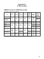
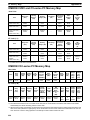
PC Memory Maps . . . . . . . . . . . . . . . . . . . . . . . . . . . . . . . . . . . . . . . . . . . . . . . . . . . . . . . . . .
Keycode Tables . . . . . . . . . . . . . . . . . . . . . . . . . . . . . . . . . . . . . . . . . . . . . . . . . . . . . . . . . . . .
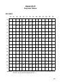
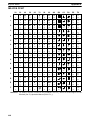
Index . . . . . . . . . . . . . . . . . . . . . . . . . . . . . . . . . . . . . . . . . .
Revision History . . . . . . . . . . . . . . . . . . . . . . . . . . . . . . . . .
viii
423
429
441
445
447
449
453
About this Manual:
This manual describes the basic functions and operation procedures of the NT-series NT31, NT31C,
NT631, and NT631C Programmable Terminals, their operations when connected to a PC (Programmable
Controller) or other host, and includes the sections described below.
Please read this manual carefully and be sure you understand the information provided before attempting
to install and operate the Programmable Terminal.
Section 1 describes the functions of the PT.
Section 2 gives basic information on the method for connecting to the host and communication methods,
and describes the names and functions of the parts of the PT.
Section 3 how to use the functions provided by the PT.
Section 4 gives an overview of memory link operations and contains explanations centered on communications between the PT and host when using memory link.
Section 5 presents a collection of simple practical examples that will give you hints on how to make best
use of the functions of the PT.
Section 6 describes the action to take when PT errors occur.
The Appendices provide the specifications, compatibility with screen data of other PT models, NT30/620
emulation mode, PC memory maps, and keycode tables.
! WARNING Failure to read and understand the information provided in this manual may result in
personal injury or death, damage to the product, or product failure. Please read each
section in its entirety and be sure you understand the information provided in the section
and related sections before attempting any of the procedures or operations given.
ix
Related Manuals:
Related manuals are listed below.
The symbol at the end of the catalog number is the revision number.
Connecting and Setting Up the Programmable Terminal
NT31 and NT31C PT Setup Manual (V062-E1-)
NT631 and NT631C PT Setup Manual (V063-E1-)
These manuals are used separately for the different models of PT. They describe
connecting the Programmable Terminals to a host and peripheral devices and
settings required for communications and applications.
The functions and actual operating messages for the NT31, NT31C, NT631, and
NT631C PTs are provided in the Reference Manual (V064-E1-).
Programmable Terminal Functions and Operation
NT31/31C/631/631C PT Reference Manual (V064-E1-, this manual)
This manual is used for any of the following PTs: NT31, NT31C, NT631, and
NT631C. It describes screen configurations, part functions, host control methods, and other application information.
PT connection and setup procedures are described in the NT31 and NT31C PT
Setup Manual (V062-E1-) and the NT631 and NT631C PT Setup Manual
(V063-E1-).
Creating and Transferring Screen Data, and Installing the System Program
NT-series Support Tool for Windows Ver. 4.1 Operation Manual (V061-E1-)
The screens displayed on the NT31, NT31C, NT631, and NT631C PTs are
created with the Support Tool and transferred to the PT. This manual describes
how to create and transfer screen data. It also describes how to download a system program to a PT using the System Installer.
The NT-series Support Tool for Windows is normally referred to as merely the
Support Tool.
Connecting to Controllers Not Made by OMRON
PC Connection Manual (V042-E1-)
The NT31, NT31C, NT631, and NT631C PTs can be connected to controllers in
the following series: Mitsubishi’s A Series and FX Series. This manual describes
the connection and setup methods for these controllers.
The NT-series Support Tool for Windows Version 4.1 is required to connect the
NT31, NT31C, NT631, and NT631C PTs to Mitsubishi controllers.
x
SECTION 1
General
This section provides fundamental information about the functions and features of the PTs, types of connection, communication methods, etc. This information will enable you to understand the applications of the PTs.
1-1
1-2
1-3
1-4
1-5
1-6
Role and Operation of the PT . . . . . . . . . . . . . . . . . . . . . . . . . . . . . . . . . . . . . . . . . . . . . . . .
1-1-1 Operation of a PT at an FA Production Site . . . . . . . . . . . . . . . . . . . . . . . . . . . . .
1-1-2 Operations of the PT . . . . . . . . . . . . . . . . . . . . . . . . . . . . . . . . . . . . . . . . . . . . . . .
Functions of the NT31/NT31C and NT631/NT631C . . . . . . . . . . . . . . . . . . . . . . . . . . . . .
1-2-1 Features . . . . . . . . . . . . . . . . . . . . . . . . . . . . . . . . . . . . . . . . . . . . . . . . . . . . . . . . .
1-2-2 Comparison between NT31, NT31C, NT631, and NT631C . . . . . . . . . . . . . . . . .
1-2-3 Additional Functions of the V2 Versions . . . . . . . . . . . . . . . . . . . . . . . . . . . . . . . .
1-2-4 Comparisons with Earlier Models . . . . . . . . . . . . . . . . . . . . . . . . . . . . . . . . . . . . .
1-2-5 Principal Functions of NT31/NT31C and NT631/NT631C . . . . . . . . . . . . . . . . .
1-2-6 Displays . . . . . . . . . . . . . . . . . . . . . . . . . . . . . . . . . . . . . . . . . . . . . . . . . . . . . . . . .
System Configuration . . . . . . . . . . . . . . . . . . . . . . . . . . . . . . . . . . . . . . . . . . . . . . . . . . . . . .
1-3-1 Peripheral Devices That Can Be Connected . . . . . . . . . . . . . . . . . . . . . . . . . . . . .
1-3-2 Connecting to the Host . . . . . . . . . . . . . . . . . . . . . . . . . . . . . . . . . . . . . . . . . . . . .
Communications with the Host . . . . . . . . . . . . . . . . . . . . . . . . . . . . . . . . . . . . . . . . . . . . . .
1-4-1 Direct Connection Function . . . . . . . . . . . . . . . . . . . . . . . . . . . . . . . . . . . . . . . . . .
1-4-2 Host Link . . . . . . . . . . . . . . . . . . . . . . . . . . . . . . . . . . . . . . . . . . . . . . . . . . . . . . . .
1-4-3 NT Link . . . . . . . . . . . . . . . . . . . . . . . . . . . . . . . . . . . . . . . . . . . . . . . . . . . . . . . . .
1-4-4 Functions of the Allocated Bits and Words . . . . . . . . . . . . . . . . . . . . . . . . . . . . . .
1-4-5 Connecting to other Companies’ PCs . . . . . . . . . . . . . . . . . . . . . . . . . . . . . . . . . .
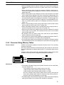
Communication by Using Memory Link . . . . . . . . . . . . . . . . . . . . . . . . . . . . . . . . . . . . . . .
1-5-1 Memory Link . . . . . . . . . . . . . . . . . . . . . . . . . . . . . . . . . . . . . . . . . . . . . . . . . . . . .
1-5-2 Comparison between Direct Connection and Memory Link . . . . . . . . . . . . . . . . .
1-5-3 Memory Link Online Transfer Function . . . . . . . . . . . . . . . . . . . . . . . . . . . . . . . .
Before Operating . . . . . . . . . . . . . . . . . . . . . . . . . . . . . . . . . . . . . . . . . . . . . . . . . . . . . . . . .
2
2
3
4
4
5
6
7
10
12
18
18
19
21
21
22
22
23
28
29
29
29
30
31
1
Section
Role and Operation of the PT
1-1
1-1
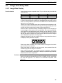
Role and Operation of the PT
The NT31, NT31C, NT631, and NT631C are sophisticated display units (Programmable Terminals) which automatically display information and can also be
used for operations when necessary. The following gives a general description
of the role and operation of the PT for those using a Programmable Terminal
(PT) for the first time.
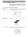
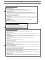
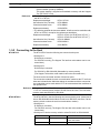
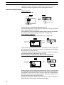
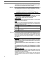
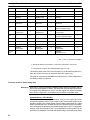
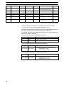
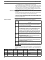
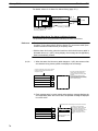
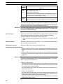
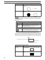
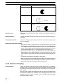
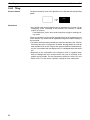
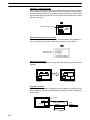
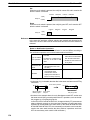
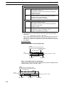
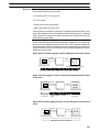
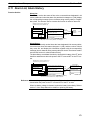
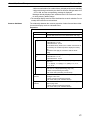
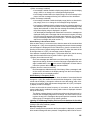
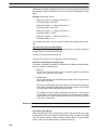
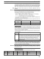
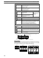
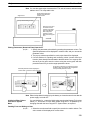
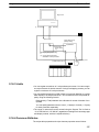
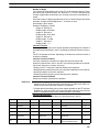
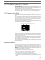
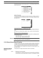
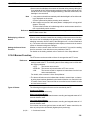
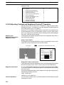
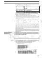
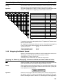
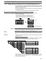
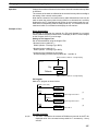
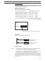
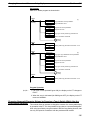
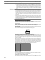
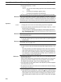
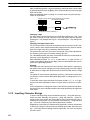
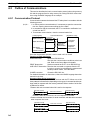
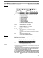
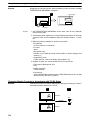
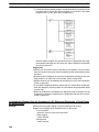
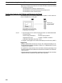
1-1-1 Operation of a PT at an FA Production Site
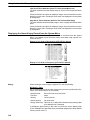
Production Line Status
Monitoring
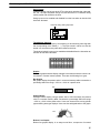
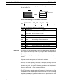
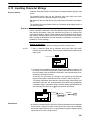
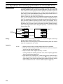
The PT displays real-time information about the system and equipment operating status, etc. Its power of expression is enhanced by graphs and other visuals,
making the displays easy to understand.
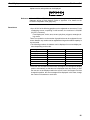
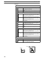
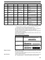
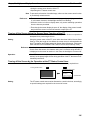
Production Control (3)
Product
Today’s target
Current production
Number defective
Number repaired
560
305
2
7
441
275
8
15
% achieved
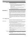
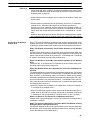
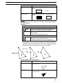
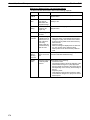
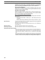
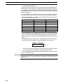
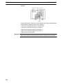
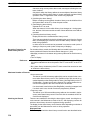
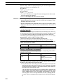
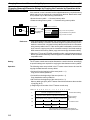
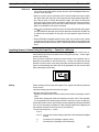
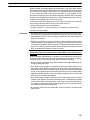
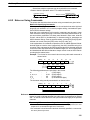
Directions to Workers on
the Shop Floor
The PT warns of system or equipment failures and prompts the appropriate remedial action.
Alarm
Assembly line B
Positioning pin
is defective. Line stopped.
Check the following.
1. Defective pin L3
2. Position of dog M2
3. Mounting of photosensor P5
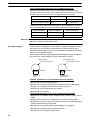
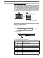
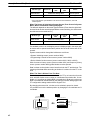
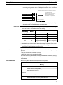
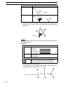
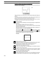
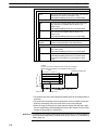
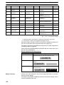
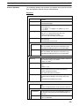
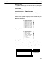
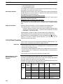
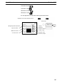
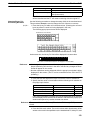
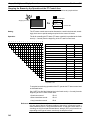
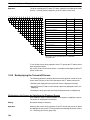
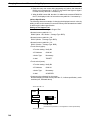
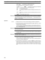
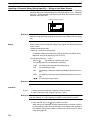
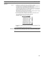
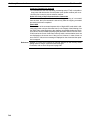
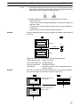
Panel Switch Functions
Setting touch switches on the PT allows workers to use the PT as an operating
panel; the results of the operations are transmitted to the host.
Electroplating control
Transport
Electr.
head
Wash.
head
Corr. prv.
head
Electrolyte
Wash
Corr.
prv.fluid
Clamp
Unclamp
Adv.
Int. stop
Rev.
2
Section
Role and Operation of the PT
1-1
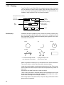
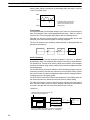
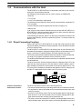
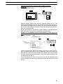
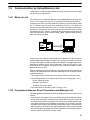
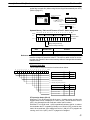
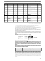
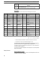
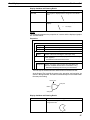
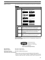
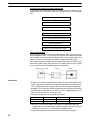
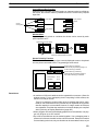
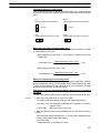
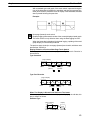
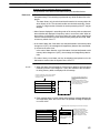
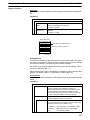
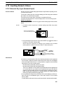
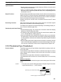
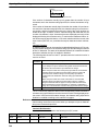
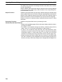
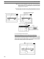
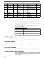
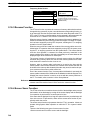
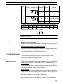
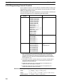
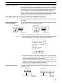
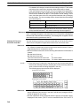
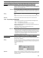
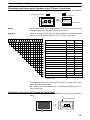
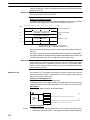
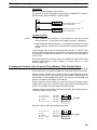
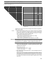
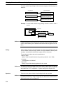
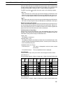
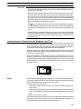
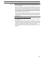
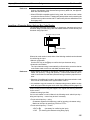
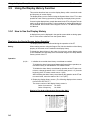
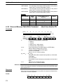
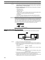
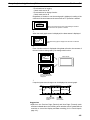
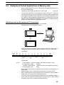
1-1-2 Operations of the PT
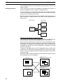
Displays Screens
The information to be displayed (screen data) can be created on a computer using the Support Tool and stored in the PT. The screen data can be displayed on
the PT in response to instructions from the host or touch switch operation.
Host
The screen data designated by
instructions from the host or touch
switch operation is displayed.
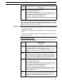
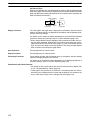
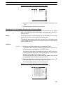
Receives Data from a
Host
The PT can be connected to the host by a host link or NT Link and receive necessary data from the host.
Host link, NT Link
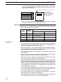
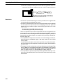
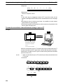
Sends Data to a Host
Host
Data input using the touch panel (switch ON/OFF statuses, numeric values,
character strings) can be transmitted to the host.
Host
Touch panel
ON/OFF information, numeric
data, etc.
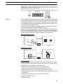
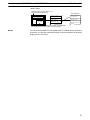
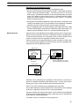
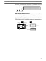
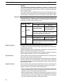
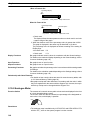
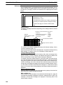
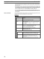
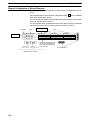
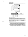
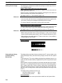
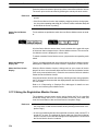
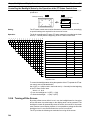
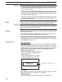
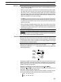
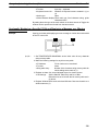
Screen Data
The screen data to be displayed on the PT can be created on a personal computer using the Support Tool. Connect the PT to the personal computer with an
RS-232C cable and transmit the screen data to the PT.
Create screen data.
RS-232C
Personal
computer
(Support Tool)
Screen data
When the host is connected at serial port A,
the personal computer is only connected
when communicating screen data between
the PT and Support Tool.
3
Section
Functions of the NT31/NT31C and NT631/NT631C
1-2
1-2
Functions of the NT31/NT31C and NT631/NT631C
The NT31/NT31C and NT631/NT631C have the following features.
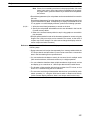
1-2-1 Features
Slim Construction
• The PT is slimmer but retains the same functions. The depth is 50 mm max.
when mounted in a panel with the recommended thickness (1.6 to 4.8 mm.)
• The communication cable connectors are housed in the unit so that they do not
protrude from the unit.
Ideal Construction for an FA Environment
• NT31-ST121-EV2: STN monochrome LCD type with backlight
• NT31C-ST141-EV2: STN color LCD type with backlight
• NT631-ST211-EV2: High-contrast EL display
• NT631C-ST141-EV2: STN color LCD type with backlight
• NT631C-ST151-EV2: TFT color bright LCD type with backlight
• The backlight unit and battery can be replaced onsite.
• Waterproofing meets NEMA4 and IP65F standards. (The panel can not be
used in some IP65F environments requiring long-term exposure to oil.)
NT31/NT31C
NT631/NT631C
640 dots
320 dots
240 dots
480 dots
Wide angle of visibility
Touch Switch Operation
Compatibility with Other PTs
Contrast and brightness are adjustable by touch switch operations. (This feature
is not available on the NT631 and NT631C-ST151-EV2.)
• There is upward compatibility between the following models for screen data
and user programs: NT20S, NT30, NT30C, NT600S, NT31, NT31C NT610G,
NT610C, NT620S, NT620C, NT625C, NT631, NT631C. (After being read to
the Support Tool, screens must be modified in accordance with the screen
size. Depending on the function used, partial modification of programs may
also be necessary. For details, refer to Appendix B Compatibility with Screen
Data of Other PT Models (page 445) and the Support Tool manual.)
• The panel cut-out dimensions for the NT31/NT31C are the same as the dimensions for the NT30/NT30C and the panel cut-out dimensions for the
NT631/NT631C are the same as the dimensions for the NT625C.
Two Ports Featured as Standard:
Port A for Common Use by Support Tool/Host and Port B for Exclusive Use by the Host
• Communication with the host is possible via another port while connected to
the Support Tool.
• Reading bar code data from a bar code reader is possible via another port
while communicating with the host.
4
Section
Functions of the NT31/NT31C and NT631/NT631C
1-2
Rapid System Program & Screen Data Changes Possible Using a Memory Unit.
• Installing a memory unit (type NT-MF261) on the rear of the NT31/NT31C or
NT631/NT631C makes it easy to write screen data into the PT onsite. This enables a rapid response to setup changes.
• The NT31/NT31C and NT631/NT631C can store a system program into a
memory unit. This enables the system to handle more flexible setups.
Screen Data Check
Function
Screen data can be checked simply by operations in the NT31/NT31C or
NT631/NT631C system menu, without connecting up to the Support Tool.
Increased Screen Data
Capacity (NT31/NT31C)
The data capacity of 1 MB is twice that of the NT30/NT30C, enabling storage of a
larger quantity of screen data.
Large Increase in
Maximum Number of
Registered Elements
The number of elements that can be registered on one screen has been considerably increased, making it possible to create more expressive screens. For details, refer to Display Restrictions (page 425).
Binary Data can be Read
to/Written from the Host
It is now possible to write binary data stored in words at the host directly to the PT.
This makes data conversion by a program at the host unnecessary, reducing the
load on the host.
Character Display Using
High Definition Fonts
Any quadrupled characters are displayed with a 32 dot high-definition font.
Simple Upgrades
By using the system installer supplied with the ZJCAT1-EV4 Support Tool, the
system program at the NT31/NT31C or NT631/NT631C can be changed easily
from a personal computer.
Complies with
International Standards
The PTs meet UL/CSA standards and EC directives.
Compatible with Other
Vendors’ Devices
Compatible with the Mitsubishi A-series (Calculator Link) and FX-series (Programming Console) Sequencers. Specialized system programs can be installed
that allow the NT31/NT31C or NT631/NT631C to be controlled from other companies’ Sequencers.
Multiple Windows
Up to 3 windows can be displayed simultaneously in the normal display. A
9-word window control area has been allocated to the host; the contents of these
9 words can be changed from the Host to open, close, and move windows.
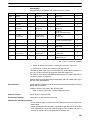
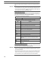
1-2-2 Comparison between NT31, NT31C, NT631, and NT631C
NT31/NT31C
Two models are available: the monochrome NT31 and the 8-color NT31C. The
differences between the NT31 and NT31C are shown in the following table.
Item
NT31
NT31C
Front panel
color
NT31-ST121-EV2 (Beige)
NT31-ST121B-EV2 (Black)
NT31C-ST141-EV2 (Beige)
NT31C-ST141B-EV2 (Black)
Display
STN monochrome LCD
(with white backlight)
STN color LCD
(with white backlight)
Note Beige and black are the front panel colors of each NT31/NT31C type.
NT631/NT631C
Item
Two NT631 models are available: the NT631 has a monochrome (yellow EL)
display and the NT631C has an 8-color display. The differences between the
NT631 and NT631C are shown in the following table.
NT631-ST211-EV2
Front panel NT631-ST211-EV2 (Beige)
color
NT631-ST211B-EV2 (Black)
Display
Monochrome EL display
NT631C-ST141-EV2
NT631C-ST151-EV2
NT631C-ST141-EV2 (Beige)
NT631C-ST151-EV2 (Beige)
NT631C-ST141B-EV2 (Black)
NT631C-ST151B-EV2 (Black)
STN color LCD (with white backlight) Bright TFT color LCD (with white
backlight)
Note Beige and black are the front panel colors of each NT631/NT631C type.
5
Functions of the NT31/NT31C and NT631/NT631C
Section
1-2
1-2-3 Additional Functions of the V2 Versions
The V2 versions of NT31/NT31C and NT631/NT631C are supplemented and
enhanced by the following functions.
High-speed 1:N NT Link
The V2 versions are compatible with the high-speed 1:N NT Link as well as the
earlier standard 1:N NT Link.
Additional Mathematical
Functions
Operands (values referenced by equations) can be registered to allow the PT to
perform calculations automatically and write the results of those calculations to
numeral memory tables or words in the host.
Device Monitor Function
The new device monitor function can be used to change the PC’s operating
mode or display/change values in the PC’s memory areas. The PVs of several
words can be listed with the device monitor.
Interlock Function
PT operations and inputs can be disabled from the PC if interlock bits have been
allocated in the PC for the corresponding PT touch switches, numeric inputs, or
string inputs.
Improved Lamp/Touch
Switch Guide Characters
The following displays can be performed with lamp or touch switch guide characters:
• Display several lines of guide characters.
• Switch the display between different guide characters when OFF and ON.
• Display the numeral memory table contents as guide characters.
• Display the string memory table contents as guide characters.
NT30/NT30C and
NT620S/NT620C/NT625C
Compatible
The word configuration of the PT status control area and PT status notify area
can be set to emulate those of the NT30/NT30C or NT620S/NT620C/NT625C;
this mode is called NT30/620 compatible mode.
When the PT is operating in NT30/620 compatible mode, it will be equivalent to
an NT30/NT30C or NT620S/NT620C/NT625C in the functions listed below. The
PT retains full V2 functionality in all functions other than the ones listed below.
Refer to Appendix C NT30/620 Compatible Mode for more details.
• Word configuration and functions of the PT status control area and PT status
notify area
• Image/library codes
• Insertion of image/library data into character strings
Additional CS1 Data
Areas Accessible
Data areas in CS1 PCs that were previously inaccessible can be accessed. The
data areas listed below can be accessed (read/written) through a 1:N NT Link
with the CS1 PC. (These areas cannot be accessed through a Host Link connection.)
All banks in the EM Area, timer completion flags (TU), counter completion
flags (CU), Work Area (WR), task flags (TK), and the HR Area.
Recipe Function
You can set the data (numeric values) for multiple words in record units using the
tabular elements on the PT screen, and write these settings in a single operation
to words on the host (i.e., PLC or PT memory) using a touch switch operation on
the PT Unit. Also, multiple words of numeric data can be read from the host in
one operation. In this way, groups of parameter settings can be edited at the PT
Unit, and written to or read from the host.
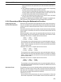
Adjusting Contrast and
Brightness During PT
Operation
You can display the brightness and contrast adjustment screen using either the
touch switch or commands from the host, even while the PT is in operation.
6
Section
Functions of the NT31/NT31C and NT631/NT631C
1-2
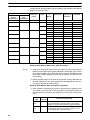
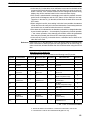
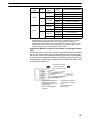
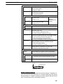
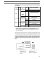
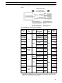
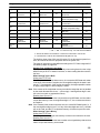
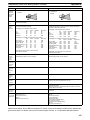
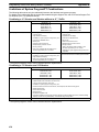
1-2-4 Comparisons with Earlier Models
Comparison between NT30/NT30C and NT31/NT31C
Item
NT30/NT30C
NT31/NT31C
Compatible Support Tool(s)
NT-ZJCAT1-EV4 or
NT-ZA3AT-EV2
NT-ZJCAT1-EV4
DIP switches
On rear of unit
None (software settings)
Use of B7A unit
Possible
Not possible
Use of memory unit
Not possible
Possible
RS-232C interface
Connector (9-pin) also used as port for
screen data transfer.
- Serial port A connector (also used
for screen data transfer, 9-pin)
- Serial port B connector (for host
communications only, 25-pin)
RS-422A/485 interface
Terminal block
Serial port B (25-pin D-SUB connector)
Replacement backlight
NT30-CFL01/NT30C-CFL01
NT31C-CFL01 (common use)
NT31/NT31C system program data
NT-ZS3AT-EV1
(including system installer)
The system installer and system
program data are supplied with the
Support Tool.
High-speed 1:N NT Link
Not possible
Possible1
Memory
Link
System program
Exclusive use by Memory Link
Same as OMRON connection
Screen data
Shared with OMRON connection
Exclusive use by Memory Link
LCD contrast adjustment
By a control on the rear of the unit
By touch panel operation
Backlight brightness adjustment
Not possible
By touch panel operation
Number of user-registered screens
2,000 max.
3,999 max.
Screen data capacity*2
512 KB
1 MB
Numeral string data
1,000 max.
2,000 max.
Character string data
1,000 max.
2,000 max.
Bit data
256
1,000 max.
Mathematical table
None
256 max.
Calculations can be executed
automatically in the PT.*1
Image data
224 max.
4,095 max.*3
Library data
896 max.
12,288 max.*3
Method for storing numeric values
(numeral memory data and PT status
control area)
Fixed as BCD (binary coded decimal)
Selectable from BCD (binary coded
decimal) or binary
PT status control area size
4 words
5 words (partial change of contents)*3
PT status notify area size
3 words
2 words (partial change of contents)*3
Window control area size
None
9 words*4
Registering continuous screen
Possible
Not possible (Use a screen switchover
as a substitute.)
Lamp/Touch switch guide characters
Fixed display (1 line only)
-
Interlock function
None
Operations can be disabled from the
PC by allocating interlock bits to the
corresponding touch switch, numeral
input, or character string input.*1
Device monitor function
Not possible
Possible*1
(User program memory)
Multiple lines can be displayed*1
ON/OFF switching is possible*1
Numeral display is possible*1
Character string display is possible*1
7
Section
Functions of the NT31/NT31C and NT631/NT631C
Item
NT30/NT30C
1-2
NT31/NT31C
Recipe function
None
Possible*1
Accessible CS1 PC data areas
---
The data areas listed below can be
accessed in addition to the data areas
accessible with the NT30/NT30C.*5
- EM banks (EM_0 to EM_C)
- Timer completion flags (TU)
- Counter completion flags (CU)
- Work Area (WR)
- Task flags (TK)
- HR Area
*1:
*2:
*3:
*4:
*5:
These functions are available only in V2 versions of the NT31/NT31C.
This is the capacity of the flash memory that stores screen data.
The values are the same as the NT30/NT30C when the PT is in NT30/620 compatible mode.
The window control area can be used only in the V versions of the NT31/NT31C.
These data areas are accessible only when the PT is connected to the CS1 PC in a 1:N NT Link. (They are not
accessible through host link communications.)
For differences in programming, refer to Appendix B Compatibility with Screen
Data of Other PT Models on page 429.
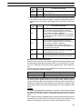
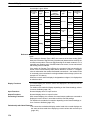
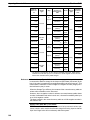
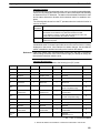
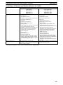
Differences between the NT620S/NT620C/NT625C and NT631/NT631C
Item
NT620S/NT620C/NT625C
NT631/NT631C
Compatible Support Tool(s)
NT-ZJCAT1-EV4 or
NT-ZA3AT-EV2
NT-ZJCAT1-EV4
DIP switches
On rear of unit
None (software settings)
Use of memory unit
Not possible
Possible
RS-232C interface
Connector (9-pin) also used as port for
screen data transfer.
- Serial port A connector (also used
for screen data transfer, 9-pin)
- Serial port B connector (for host
communications only, 25-pin)
RS-422A/485 interface
NT620S/NT620C: None
NT625C: Terminal block (Select
RS-232C or RS-422A/485 with the DIP
switch.)
Terminal block (A memory switch can
set the RS-232C connector as serial
port B.)
Replacement backlight
NT620C-CFL01 (NT620C)
NT610C-CFL02 (NT625C)
NT631C-CFL01 (for ST151)
NT631C-CFL02 (for ST141)
NT631/NT631C system program
data
NT620-ZS3PC/ZS3DV-EV1
(including system installer)
The system installer and system
program data are supplied with the
Support Tool.
High-speed 1:N NT Link
Not possible
Possible*1
Memory
Link
System program
Exclusive use by Memory Link
Same as OMRON connection
Screen data
Shared with OMRON connection
Exclusive use by Memory Link
LCD contrast adjustment
By a control on the rear of the unit
Adjustable with touch panel operation.
(NT631-ST141-V2 only)
Backlight brightness adjustment
Not possible
Adjustable with touch panel operation.
(NT631-ST141-V2 only)
Number of user-registered screens
2,000 max.
3,999 max.
Screen data capacity*2
1 MB
(User program memory)
NT620S: 512 KB
NT620C/NT625C: 1 MB
Numeral string data
1,000 max.
2,000 max.
Character string data
1,000 max.
2,000 max.
Bit data
256
1,000 max.
Mathematical table
None
256 max.
Calculations can be executed
automatically in the PT.*1
8
Section
Functions of the NT31/NT31C and NT631/NT631C
Item
NT620S/NT620C/NT625C
1-2
NT631/NT631C
Image data
224 max.
4,095 max.*3
Library data
896 max.
12,288 max.*3
Method for storing numeric values
(numeral memory data and PT
status control area)
Fixed as BCD (binary coded decimal)
Selectable from BCD (binary coded
decimal) or binary
PT status control area size
4 words
5 words (partial change of contents)*3
PT status notify area size
3 words
2 words (partial change of contents)*3
Window control area size
None
9 words*4
Registering continuous screen
Possible
Not possible (Use a screen switchover
as a substitute.)
Lamp/Touch switch guide
characters
Fixed display (1 line only)
-
Interlock function
None
Operations can be disabled from the
PC by allocating interlock bits to the
corresponding touch switch, numeral
input, or character string input.*1
Device monitor function
Not possible
Possible*1
Recipe function
None
Possible*1
Accessible CS1 PC data areas
---
The data areas listed below can be
accessed in addition to the data areas
accessible with the NT30/NT30C.*5
- EM banks (EM_0 to EM_C)
- Timer completion flags (TU)
- Counter completion flags (CU)
- Work Area (WR)
- Task flags (TK)
- HR Area
Multiple lines can be displayed*1
ON/OFF switching is possible*1
Numeral display is possible*1
Character string display is possible*1
*1: These functions are available only in V2 versions of the NT631/NT631C.
*2: This is the capacity of the flash memory that stores screen data.
*3: The values are the same as the NT620S/620C/NT625C when the PT is in NT30/620 compatible mode.
*4: The window control area can be used only in the V versions of the NT631/NT631C.
*5: These data areas are accessible only when the PT is connected to the CS1 PC in a 1:N NT Link. (They are not
accessible through host link communications.)
For differences in programming, refer to Appendix B Compatibility with Screen
Data of Other PT Models on page 429.
9
Functions of the NT31/NT31C and NT631/NT631C
Section
1-2
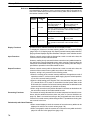
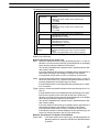
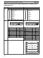
1-2-5 Principal Functions of NT31/NT31C and NT631/NT631C
The following are the principal functions of the NT31/NT31C and
NT631/NT631C.
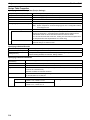
Functions relating to data display
Character display
Characters of various sizes can be displayed. Characters can be flashed and displayed in reverse
video. High grade fonts are available for the characters with their size enlarged.
Graphic display
Polylines, rectangles, polygons, circles, circular arcs, and sector shapes can be displayed. They can
also be tiled with various patterns, flashed, or displayed in reverse video.
Memory data display
The contents of character string memory tables and numeral memory tables can be displayed. The
contents of memory tables can be changed from the host.
Graph display
Not only bar graphs but also broken line graphs, trend graphs, and analogue meter graphs can be
displayed using numeral memory tables
Lamp display
Lamps can be turned on and flashed under the control of the host. It is also possible to display different
graphics in the ON and OFF states.
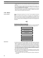
Alarm list/history display
Warning messages are automatically displayed in a list in response to the state of a host bit. The time
and the number of times of the messages appeared can also be displayed.
Functions relating to data output
Buzzer
A built-in buzzer can be sounded.
Screen printing
A hard copy of the currently displayed screen can be printed at the
printer connected to the PT.
10
Functions of the NT31/NT31C and NT631/NT631C
Section
1-2
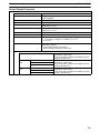
Functions relating to data input
Input by touch switches
Data can be input by simply touching touch switches displayed on the screen.
The possible functions of touch switches include sending data to the host and changing the screen display.
Inputs can be enabled and disabled from the host when interlock bits have been allocated.
Pop-up window function
A window overlaying the currently displayed screen can be alternately opened and closed by pressing a touch switch.
In addition to fixed character and graphic displays, control keys and character keys created as touch switches can also be set
inside the window. A maximum of three windows can be displayed simultaneously. Since the window need only be opened when
input is required, the screen can be used efficiently.
Numeral/character string setting function
Numeric keys and character keys can be assigned to touch switches so that numeric values and character strings can be input at
the operation site.
The input data is written to numeral/character string memory tables and also sent to the host. It is also possible to disable input by
control from the host.
Recipe function
Several words of numeric data can be edited at the PT Unit, and written to or read from the host in one operation.
Input from a bar code reader
Data read with a bar code reader can be input to a character string input field.
Functions relating to communication
Communications with the host
The PT can communicate with the host by four methods: host link, 1:1 NT Link, 1:N NT
Link (standard and high-speed) and Memory link. Data can be read from the host, and
data input by means of touch switches and numeral/character string settings can be
sent to the host. It is also possible to connect with other model PCs.
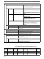
Functions relating to the system
System menu
System settings and maintenance can be performed by selecting from system menus displayed on the screen.
Creation of screen data
Screen data created using the Support Tool at a personal computer can be transferred and stored in the built-in screen data memory.
Resume function
The status and memory table contents of the NT31/NT31C and NT631/NT631C immediately before its operation is stopped can be stored while
operation is stopped, or while the power is off, and then displayed on the screen again when operation is restarted.
Screen saver function
This function serves to extend the service life of the backlight and prevent the formation of an afterimage on the screen.
Clock function
The time can be displayed in accordance with the internal clock data.
Programming Console function
The PT can perform the same operations as a C200H-PR027-E Programming Console when the PT is connected to a CPM1, CPM2A, CPM2C,
CQM1, CQM1H, C200HX/HG/HE(-Z)E, or SRM1 PC in a 1:1 NT Link connection, or a CS1G/CS1H PC in a 1:N NT Link connection.
Device Monitor function
When the PT is connected to a PC in a 1:1 NT Link or 1:N NT Link, the PT can be used for operations such as changing the PC’s operating
mode, displaying or changing the PVs of words, or reading the error log.
System program install function
The system program of the NT31/NT31C or NT631/NT631C can be changed by using the system installer supplied with the Support Tool (NTZJCAT-EV). It can also be installed by using a memory unit (NT-MF261).
Screen display history function/alarm history function
The screen display history function records the time at which specific screens are displayed and the number of times they are displayed. The
alarm history function records the time at which specific bits at the host are turned ON and the number of times they are turned ON.
Trend graph logging function and background function
Changes in the contents of numeral memory tables displayed in trend graphs can be recorded (logging function). Also, the record can be maintained even when the trend graph is not displayed (background function).
Mathematical function
This function allows calculations to be executed regularly during PT operation when mathematical tables have been set in screen data. Arithmetic operations, bit operations, logic operations, and comparison operations can be performed. Operations with up to 5 terms are possible.
11
Section
Functions of the NT31/NT31C and NT631/NT631C
1-2
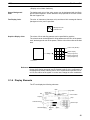
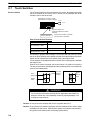
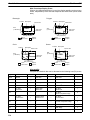
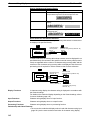
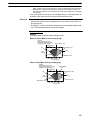
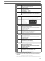
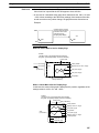
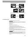
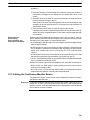
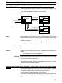
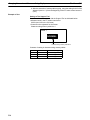
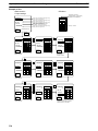
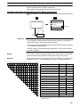
1-2-6 Displays
The NT31/NT31C and NT631/NT631C can display various kinds of elements
such as characters, numeric values, graphs, lamps, and touch switches, on a
screen. The screen data displayed by the NT31/NT31C and NT631/NT631C are
created by using the Support Tool at a personal computer.
Example NT31/NT31C Display
Characters
(fixed display)
Line 1 Status
Stop
Characters
(character string display)
Machine name: NT31C-ST141
Production qty.: 137 units
Bar
graph
25%
0%
Stage 1
Fixed Displays
Check 1
50%
Stage 2
Touch
switches
Restart
100%
Numeric values
(numeral display)
Check 2
Lamps
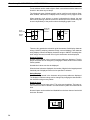
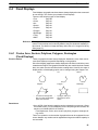
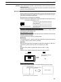
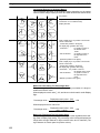
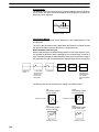
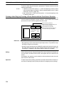
Characters and various graphics (circles, circular arcs, sectors, polylines, polygons and rectangles) whose display does not have to be changed, and mark
data, image data, and library data that has already been registered, can be written directly onto the screen.
Circle
Arc
Sector
Polyline
Polygon
Rectangle
* A continuous straight line with
up to 256 points can be drawn.
* A polygon with up to 255
vertices can be drawn.
Marks are graphics comprising 16 by 16 dots that can be used as characters.
They can be used as custom characters within character strings.
Image data contain graphics comprising any required area of dots. They are registered in advance and as many as required can be displayed at any position on
the screen.
Windows bit map (BMP) data can be used for images.
There is a two-color mode, in which the display color and background color of the
image are specified when it is registered in a screen, and an eight-color mode in
which colors are assigned to the image in advance.
Since image data is composed of dots, it requires a large data size but offers
great powers of expression.
12
Section
Functions of the NT31/NT31C and NT631/NT631C
1-2
Library data contain combinations of fixed display graphics registered as a
single graphic. They are registered in advance and as many as required can be
displayed at any position on the screen.
Since it is generated by combining graphics, library data has a small data size.
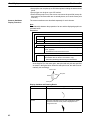
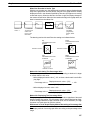
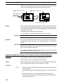
Mark
Lamps
Image data
Library data
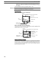
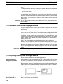
These are graphics whose display status changes in accordance with the states
of bits at the host. Squares, circles, sectors and polygons can be used for lamps
(normal (standard) lamps). In accordance with the status of the host bit, they can
be lit (displayed in reverse video) or flashed (repeated alternation between normal and reverse video display states).
Lamps can also display different image/library data for the ON and OFF states of
the host bit (such lamps are called image/library lamps).
There are four standard lamp guide characters: fixed display character strings,
ON/OFF switching character strings, numeral displays, and character string displays. When fixed display character strings or ON/OFF switching character
strings are used, several lines of guide characters can be displayed.
Normal (Standard) Lamps
ON
ON
Host
Unlit state
Lit state
Image/Library Lamps
ON
Unlit state
Host
Lit state
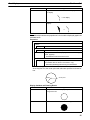
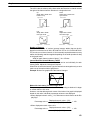
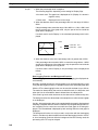
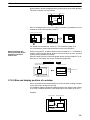
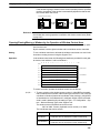
Touch Switches
These switches can be set at any location on the screen. Pressing a touch switch
on the screen where a touch switch has been set can have the following effects:
• Notification to a host bit (input notification function)
• Changing the displayed screen (screen switching function)
• Input of a numeric value or character string (input key function)
• Copying of a numeric value or character string (copy key function)
• Shifting to another numeric value or character string input field (cursor moving
key function)
• Obtaining a hard copy of the screen (screen print function)
• Opening / Closing a window
• Moving a window
13
Section
Functions of the NT31/NT31C and NT631/NT631C
1-2
Touch switches can be made to light or flash in accordance with the status of a
host bit in the same way as lamps.
The following 8 types of display graphic can be used for touch switches: Standard, shadow, 3-dimension, no display frame, rectangle, circle, polygon, sector
When rectangle, circle, polygon, or sector is selected as the shape, the area
within which pressing of the touch switch is sensed (the touch switch area) can
be set independently of the position where the display graphic is set.
Touch
switch area
When this
position is
pressed...
Shown
in
reverse
video
Display
frame
Function executed
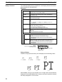
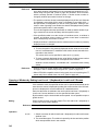
There are four standard touch-switch guide characters: fixed display character
strings, ON/OFF switching character strings, numeral displays, and character
string displays. When fixed display character strings or ON/OFF switching character strings are used, several lines of guide characters can be displayed.
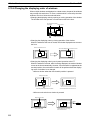
Numeral Displays
Numeric values stored in the numeral memory tables are displayed. The displayed numerals can be changed by changing the data stored in the numeral
memory tables.
Hexadecimal values can also be displayed.
When decimal values are displayed, the number of digits for the integral part and
fractional part of displayed values can be specified in advance.
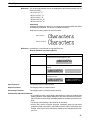
String Displays
Character strings stored in the character string memory tables are displayed.
The displayed character strings can be changed by changing the data stored in
the character string memory tables.
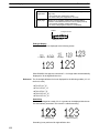
Numeral Inputs
Numeric values can be input at the PT by using touch switches. The input numeric values can also be stored in a numeral memory table and notified to the
host.
Numeral inputs can be enabled and disabled from the host when an interlock bit
has been allocated.
12345678
Input
789
456
123
0. Window
14
Section
Functions of the NT31/NT31C and NT631/NT631C
1-2
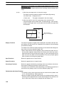
String Inputs
Character strings can be input at the PT by using touch switches, bar code readers, etc. The input character strings can also be stored in a character string
memory table and notified to the host.
String inputs can be enabled and disabled from the host when an interlock bit
has been allocated.
Character string setting input field
Display
NT31C
Input
NT31C
NT31
NT631C
Thumbwheel Switches
Numeric values can be input by incrementing or decrementing each digit with
the corresponding touch switch (+, –). The input numeric values can also be
stored in a numeral memory table and notified to the host.
Thumbwheel switch inputs can be enabled and disabled from the host when an
interlock bit has been allocated.
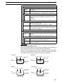
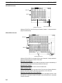
Graphs
These are graphics whose display changes in accordance with the numeric values stored in numeral memory tables. There are the following four types.
Bar Graphs
Bar graphs display the present value in a numeral memory table converted to a
percentage within the range –100% to +100% of a preset value.
60%
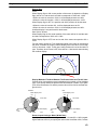
Analog Meters
Analogue meters display, using a quarter, half, or full circle shape, the present
value in a numeral memory table converted to a percentage within the range
–100% to +100% of the preset value. Users can choose from moving pointer
type and filling area type displays. Users can also add graduation to the graph.
60%
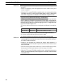
Broken Line Graphs
Broken line graphs display, in an easy-to-read form, a sequence of numeral
15
Section
Functions of the NT31/NT31C and NT631/NT631C
1-2
memory table values converted to a percentage within the range –100% to
+100% of a preset value.
100%
0%
Example showing a series of 11
numeral memory table values
(with a check mark set for the
display sign)
–100%
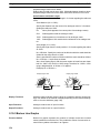
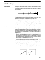
Trend Graphs
Trend graphs display chronological changes in the value in a numeral memory
table, converting the value to a percentage within the range –100% to +100% of
a preset value. The trend graph shifts position with the passage of time.
Past data can also be recorded, and the numeral memory table can be read
(sampled) even while the trend graph is not being displayed.
The user can choose to stop sampling, restart sampling, or display past data, by
pressing touch switches.
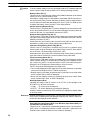
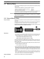
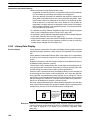
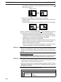
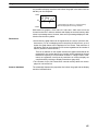
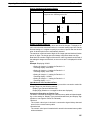
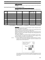
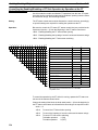
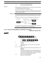
Alarm List/History
The alarm list/history function displays messages in list form, or graphics
(image/library data), in accordance with changes in bit memory table statuses.
For the alarm list, a series of bit memory tables are monitored, and messages
(contents of character string memory tables) set for bit memory tables that come
ON are displayed.
For the alarm history, bit memory tables for which the history property is set are
continually monitored, and the time when they come ON and number of times
they come ON are recorded and displayed together with the message (character string) set for the bit memory table.
The NT31/NT31C and NT631/NT631C allow selection of the display order for
the newest record first or oldest record first by memory switch setting.
The alarm list function is used to determine which bits are ON at the present
time. The alarm history function is used to determine the times at which alarms
occurred in the past and how many times alarms have occurred.
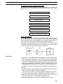
• Alarm list
Message (character string table No. 32)
set for bit memory table No. 14
Character string table No. 32
Image/library
data 113C
No.13
Bit
Character string table No. 32
Image/library data 113C
No.14
Character string table No. 54
Image/library data 1125
No.15
0
1
0
Character string table No. 50
Image/library data 1002
When the message displayed is pressed, the image/library
data (113C) set for bit memory table No. 14 is displayed.
16
HOST
A000000
L001003
D010015
1(ON)
Section
Functions of the NT31/NT31C and NT631/NT631C
1-2
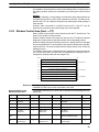
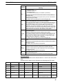
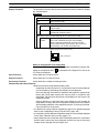
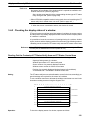
• Alarm history
Message (character string table No. 13)
set for bit memory table No. 24
Recorded data
Character string table No. 13
Character string table No. 11
Image/library data 005F
No. 22
Bit memory table No. 24
97/12/04 11:19:20
Character string table No. 12
Image/library data 102A
No. 23
Bit memory table No. 23
97/12/04 11:25:12
Character string table No. 12
Image/library
data 102B
Character string table No. 13
Image/library data 102B
No. 24
When the upper message displayed is pressed, the image/library
data (102B) set for bit memory table No. 13 is displayed.
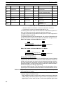
Recipe
You can set several words of numeric data at the PT in tabular format, and write it
to the host. You can also read several words of numeric data from the host and
display it on the PT screen.
17
Section
System Configuration
1-3
1-3
System Configuration
This section shows the configuration of a system that uses an NT31/NT31C and
NT631/NT631C. For details on product models, refer to the Setup Manual.
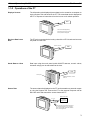
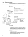
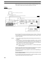
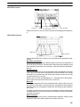
1-3-1 Peripheral Devices That Can Be Connected
The following peripheral devices can be connected to the NT31/NT31C and
NT631/NT631C.
Host
Controls the NT31/NT31C or NT631/NT631C as required while controlling
machines and monitoring the production line.
Host Link: C series, CVM1/CV series PC, SRM1
Can be connected to CPU units, host link units, and SRM1. However,
connection is not possible to some models of CPU unit and SRM1.
NT Link: CS1G/CS1H, CPM1, CQM1, C200HS, C200HX/HG/HE(-Z)E,
CVM1/CV series PCs, SRM1
Can be connected to CPU units and SRM1. However, connection is
Bar code reader
notpossible to some models.
Bar codes can be read
as character strings.
Memory Link
Can be connected to a personal computer, FA computer, etc.
Other companies’ PCs can also be connected.
Printer
For printing out the currently
displayed NT31/NT31C or
NT631/NT631C screen.
RS-232C cable
(max. 15 m)
or
RS-422A/485 cable
(max. 500 m)
Personal computer
Running Windows 95/98/NT
Support Tool
Used to create screens for the PT at
the personal computer and transmit
them to the PT, and to make PT
settings.
System installer
Used to change the system
program of the NT31/NT31C
or NT631/NT631C.
Memory unit
Can store screen
data and system
program to be read
out automatically at
startup.
NT31/NT31C or NT631/NT631C
Displays production line monitoring and instructions to the
operation site, and notifies the switch ON/OFF status and
numeric value inputs to the host.
When a 1:N NT Link is being used, up to 8 PTs can be
connected to a single PC.
• Bar code reader
V520-RH21-6 (made by OMRON)
• Recommended printers
It is also possible to use printers that can emulate an NEC PC-PR201H (using the NEC PC-PR201PL control protocol), and printers that comply with
one of the following EPSON control standards: ESC/P 24-J83C (color), or
ESC/P 24-J82 (monochrome).
If using an HP printer, make sure that it conforms to the PCL5 standard.
• Memory unit
NT-MF261 (made by OMRON)
• Support Tool
NT-series Support Tool Version 4.0 for Windows (made by OMRON)
• NT-ZJCAT1-EV4 (CD-ROM version for DOS)
• System installer
18
Section
System Configuration
1-3
System installer (made by OMRON)
The system installer is supplied as a standard accessory with the Support
Tool (NT-ZJCAT1-EV4).
Reference:
The following optional devices are available. All of them can be used either
with NT31 or NT31C.
Replacement backlight
NT31C-CFL01
Anti-reflective film (5 sheets)
NT30-KBA04
Chemical-resistant cover
NT30-KBA01
Replacement battery
C500-BAT08
The following optional devices are available. All of them can be used either with
NT631 or NT631C except for the replacement backlights.
Replacement backlight
NT631C-CFL01 (for the NT631C-ST151)
NT631C-CFL02 (for the NT631C-ST141)
Anti-reflective film (5 sheets)
NT610C-KBA04
Chemical-resistant cover
NT625-KBA01
Replacement battery
C500-BAT08
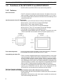
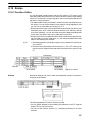
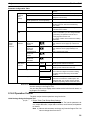
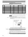
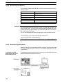
1-3-2 Connecting to the Host
NT31/NT31C
The NT31/NT31C has the following two communication ports.
• Serial port A:
D-SUB 9-pin connector
For RS-232C use only (The Support Tool and bar code readers can be connected here.)
• Serial port B:
D-SUB 25-pin connector
For RS-232C or RS-422A/485 (Selectable by memory switch)
(The Support Tool and bar code readers cannot be connected here.)
The host can be connected at either of these two ports.
The connection methods for each communication method at the PT and host
sides are indicated below. Make the settings in accordance with the communication method that can be used with the PC to be connected and the conditions at
the operation site.
Reference: When using an RS-232C/422A convertor unit (NT-AL001) with the host link or
1:1 NT Link communication method, RS-485 cannot be used. The connection
must be made with RS-232C or RS-422A.
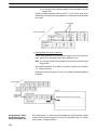
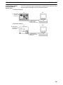
NT631/NT631C
The NT631/NT631C has the following two communication ports. (Serial port B
has an RS-422A/485 terminal block as well as an RS-232C connector; use the
memory switch to select the serial communications method.)
• Serial port A:
D-SUB 9-pin connector
For RS-232C use only (The Support Tool and bar code readers can be connected here.)
• Serial port B: Use the memory switch to select RS-232C or RS-422A/485.
Communications
Connection
Notes
RS-232C
D-SUB 9-pin connector
Cannot be used for Support Tool
or bar code reader.
RS-422A/485
Terminal block
---
19
System Configuration
Section
1-3
The host can be connected at either of these two ports.
The connection methods for each communication method at the PT and host
sides are indicated below. Make the settings in accordance with the communication method that can be used with the PC to be connected and the conditions at
the operation site.
Reference: When using an RS-232C/422A convertor unit (NT-AL001) with the host link or
1:1 NT Link communication method, RS-485 cannot be used. The connection
must be made with RS-232C or RS-422A.
20
Section
Communications with the Host
1-4
1-4
Communications with the Host
The NT31/NT31C or NT631/NT631C is connected to the host by one of the following four communication methods.
The following communications can be used to connect an OMRON PC:
• Host link
• 1:1 NT Link
• 1:N NT Link (standard or high-speed)
The following communications can be used to connect another companies’ PC
or FA computer:
• Communications protocol supported by the other company’s PC
• Memory link
In all of these communication methods that can be used with NT31/NT31C or
NT631/NT631C, data communication with host is by direct connection (Memory
link is, however, a quasi-direct connection).
In the following, the host link and NT Link that carry out the direct connection”will
be discussed. Memory link will be explained in section 1-5 Communication by
Memory Link.
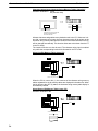
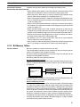
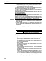
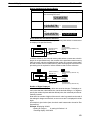
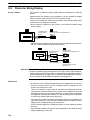
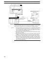
1-4-1 Direct Connection Function
With the NT31/NT31C or NT631/NT631C, the bits and words referring to data
required for display, and those for storing input data, can be allocated to any part
of the PC memory area.
The NT31/NT31C or NT631/NT631C can directly write to and read from such
allocated bits and words to change the display status of the elements on the PT
screen, control the PT operating status, and notify statuses to the host.
This function, which directly reads and writes the statuses of words and bits without using a PC program is called the direct connection function.
The words and bits allocated for direct connection are called the allocated words
and allocated bits.
The direct connection function allows the data to be displayed at the PT to be
read from the memory area in the PC and written to memory tables in the PT.
Also, the data input at the PT can be written to the memory area in the PC. The
PT screen can be changed in accordance with statuses in the PC memory area,
and the PT’s status data can be written to the PC’s memory area.
PT
PC
DM area
I/O relay area
Auxiliary relay area Timers/counters
Features of the Direct
Connection Function
The direct connection function has the following features.
• The bits and words referring to operating status and work instruction information and those for storing input data can be freely allocated to almost any area
of the PC memory.
• Since the PT can directly refer to PC bit and word data without using the program at the PC, it can be connected to the PC without changing the PC program which controls the currently running production line.
• The area to control and notify the PT statuses, including display screens, display/no display status, and buzzer output, can be freely allocated to any part of
21
Communications with the Host
Section
1-4
the PC data area. This means that the PC status can be read and controlled
just by reading this area at the PC side, without preparing a special communication program.
The direct connection function allows the PT to directly read and write almost all
bits and words in the PC and to automatically change the PT screen display. This
function can reduce the load on the PC so that its program development efficiency is improved.
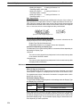
1-4-2 Host Link
The host is connected to a PT in a 1:1 connection, and the words and bits of the
host are read and displayed by host link communication. This method can be
used for connection to the majority of PC types.
1-4-3 NT Link
NT Link is a method for high-speed communication with a PC using the direct
connection function. The PCs that can be connected with the NT Link are as follows.
CPM1, CPM2A, CPM2C, CQM1, CQM1H, C200HS, C200HX/HG/HE(-Z)E,
CS1G/CS1H-E(V1), CVM1/CV-series PC (-EV1 or later version), SRM1
Besides the 1:1 NT Link method, in which one PC is connected to one PT, the
NT31/NT31C and NT631/NT631C can also use the 1:N connection NT Link
method, which allows a maximum of eight PTs to be connected to one PC port.
PCs that can be connected with the 1:N connection NT Link method are as follows: CQM1H, C200HX/HG/HE(-Z)E, CS1G/CS1H-E(V1).
The NT31/NT31C and NT631/NT631C also support OMRON’s high-speed 1:N
NT Link that provides faster 1:N communications. The only PCs that support the
high-speed 1:N NT Link are the -EV1 and higher versions of the CS1G/CS1H
PCs.
In the following sections, the term NT Link is used to refer to the NT Link communication method in general, the term 1:1 NT Link is used to refer specifically to
NT Links with a 1:1 connection, and the term 1:N NT Link is used to refer to both
standard and high speed NT Links with 1:N connections. When necessary, the
standard 1:N NT Link is distinguished from the high-speed 1:N NT Link.
Features of the NT Link
22
The NT Link has the following features.
• High-speed communications with specific types of PCs can be executed. The
NT31/NT31C and NT631/NT631C also support OMRON’s high-speed 1:N NT
Link.
• Writing in units of bits to the PC memory area is possible.
This enables the other bits of words to which a touch switch has been allocated to be allocated for other purposes (e.g. a lamp).
However, since data is written to the DM area in word units, the other bits of
words allocated to touch switches in this area cannot be used for other purposes.
• The NT Link can be used even when the PC is in the RUN mode. (When the
host link method is used, the PT switches to the monitor mode when the PC is
in the RUN mode.)
• In the case of PTs that support the standard 1:N NT Link (NT20S, NT31,
NT31C, NT600S, NT620S, NT620C, NT625C, NT631, NT631C) up to 8 PTs
can be connected to one port of the PC and used at the same time. Up to 8 PTs
(NT31, NT31C, NT631, and NT631C) can also be connected simultaneously
when the high-speed 1:N NT Link is being used. All of the PTs connected to a
PC port must use either the standard or high-speed 1:N NT Link; the two communications systems cannot share a single port.
Communications with the Host
Section
1-4
• When using a C200HX/HG/HE(-Z)E PC and standard 1:N NT Links, up to
three 1:N NT Link systems (i.e., 24 PTs) can be connected by installing a communication board in the option slot of the CPU. For details on the communication board, refer to the SYSMAC Communication Board User’s Manual
(W304-E1-).
• When using a CQM1H PC and standard 1:N NT Links, multiple 1:N NT Link
systems can be connected by installing Serial Communications Boards in the
Inner Board slots. For details on the Serial Communications Board, refer to the
CQM1H Serial Communications Board User’s Manual (W365-E1-).
• When using CS1G or CS1H PC, multiple 1:N NT Link systems (standard or
high-speed) can be connected by installing a Serial Communications Board in
the Inner Board slot or installing a Serial Communications Unit in the Backplane. For details on the communication board/communication unit, refer to
the CS1-series Serial Communication Board/Unit User’s Manual
(W336-E1-).
• If the PC being used supports the Programming Console function, the
NT31/NT31C or NT631/NT631C can be used as a Programming Console.
• If the PC being used supports the Device Monitor function, the NT31/NT31C or
NT631/NT631C can be used to change the PC’s operating mode and read/
change data in the PC’s memory areas.
The NT Link is compatible with the host link. The PT screen data and PC programs used with the host link direct connection method can be used with the NT
Link method as they are.
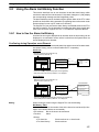
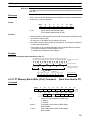
1-4-4 Functions of the Allocated Bits and Words
Elements displayed on the PT and the PT status can be allocated to the bits and
words of the PC when using the direct connection function. By changing the contents of the bits and words, the PT can be controlled by the PC. It is also possible
to send data to the PC by pressing touch switches at the PT.
Controlling the PT from
the PC
The following PT functions can be controlled from the PC.
• Screens:
Display of designated screens, confirmation of screen numbers, etc.
• Memory tables:
Writing to a memory table, copying from a memory table to another memory
table, etc.
• Lamps:
Display instructions, confirmation of display status, etc.
• Touch switches:
Display instructions, confirmation of display status, enable/disable operations, etc.
• Numeric inputs, character string inputs, thumbwheel switch inputs:
Enable/disable inputs, etc.
• System control:
Buzzer ON/OFF, display/no display status, screen printing, and other PT
statuses
Notification from the PT
to the PC
Data in the PT is sent to a PC when, for example, a touch switch is pressed. The
following 5 types of data are sent to a PC.
• PT status, screen number of currently displayed screen
• The status of touch switch inputs
• Numeric values and character string input with the numeral/character string
setting function using touch switches or a bar code reader.
23
Section
Communications with the Host
1-4
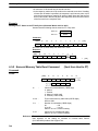
• Changes in memory tables after copying between memory tables, etc.
• Numerical results of calculations from the mathematical function
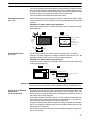
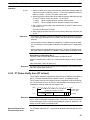
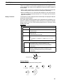
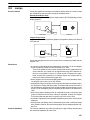
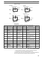
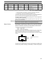
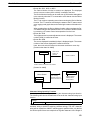
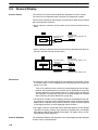
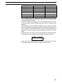
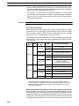
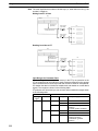
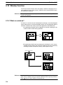
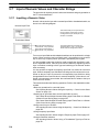
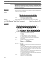
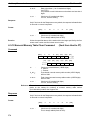
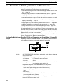
Functions of Display Elements
Lamps (page 103)
Allocation destination: Bit
PT
PC
Lamp #1 (Bit 000100)
Lit
Switch 1: ON (Bit 000100)
Unlit
Switch 2: OFF (Bit 000101)
Lamp #2 (Bit 000101)
The PC’s bit status is displayed by the lamp at the PT.
Normal (standard) lamps come on (flash) when the PC’s bit status (lamp bit) is
ON (1), and go off when it is OFF (0).
With image/library lamps, the displayed image or library data can be switched in
accordance with the ON (1)/OFF (0) status of PC bits (lamp bits).
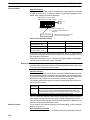
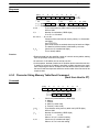
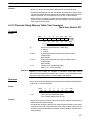
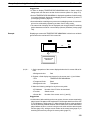
Touch Switches (page 110)
Allocation destination: Bit (lamp bit, notification bit, or interlock bit)
PC
PT
Bit 009012: ON
Touch switch #12
Bit 009012
009012
1
The lamp comes on (flashes) when the PC’s bit (lamp bit) is ON (1) and goes
OFF when it is OFF (0). When the touch switch is pressed, the PC’s notification
bit comes ON (1) or goes OFF (0).
The interlock function can also be used. An operation is enabled only while the
corresponding interlock bit allocated in the PC is ON.
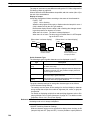
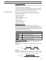
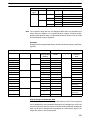
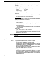
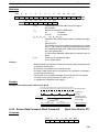
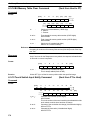
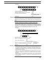
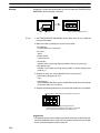
Numeral Display or Graph (Numeral Memory Tables) (page 130)
Allocation destination: Word
PT
Numeral memory
table 1 (TIM003)
PC
1612
A23C
TIM003
1
6
1
2
0005CH
A
2
3
C
Numeral memory table 150 (0005CH)
Allocate numeral memory tables to any desired words in the PC. If the contents
of the allocated words are changed while the numeral memory table data is being displayed on the screen as numeric values or lamps, the corresponding display on the screen will also change automatically. This function allows the contents of allocated words to be monitored easily.
Reading and writing are executed so that the contents of allocated words are
always the same as those of the numeral memory tables.
24
Section
Communications with the Host
1-4
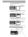
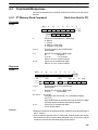
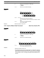
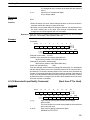
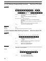
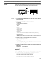
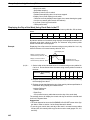
Character String Display (Character String Memory Tables)
(page 138)
Allocation destination: Word
PT
abcdef
PC
DM0100
6
1
6
2
(“a”, “b”)
DM0101
6
3
6
4
(“c”, “d”)
DM0102
6
5
6
6
(“e”, “f”)
Character string memory table 1
Number of allocated words: 3
First word: DM0100
Allocate character string memory tables to any desired words in the PC. If the
contents of the allocated words are changed while the character string memory
table data is being displayed on the screen as text, the corresponding display on
the screen will also change automatically. This function allows any desired message to be displayed easily.
Reading and writing are executed so that the contents of allocated words are
always the same as those of the character string memory tables.
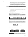
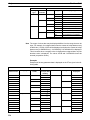
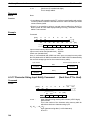
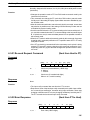
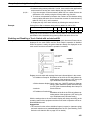
Numeric and Thumbwheel Inputs (Numeral Memory Tables) (page 183,
191)
Allocation destination: Word
Bit (interlock bits)
Numeric input
Numeral memory
table 52 (DM 1000)
DM 1000
9
5
1
1
IR 0012 C
0
1
8
Thumbwheel Switch
Numeral memory table 53 (IR 0012)
Allocate numeral memory tables to any desired words in the PC. When a value is
input or changed with the numeric input or thumbwheel switch, the new value will
be written to the numeral memory table and the contents of the words allocated
in the PC will be changed automatically. This function allows word PVs to be
changed easily from the PT.
The interlock function can also be used. The numeric and thumbwheel switch
inputs are enabled only while the corresponding interlock bits allocated in the PC
are ON.
25
Section
Communications with the Host
1-4
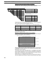
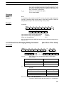
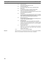
Character String Input (Character String Memory Tables) (page 201)
Allocation destination: Word
Bit (interlock bits)
ABCDEF
DM 0150 4
1
4
2
DM 0151 4
3
4
4
(“C”, “D”)
DM 0152 4
5
4
6
(“E”, “F”)
(“A”, “B”)
Character string input
Character string memory table 100
Number of allocated words: 3
First word: DM 0150
Allocate character string tables to any desired words in the PC. When text is input with a character string input, the new character string will be written to the
character string memory table and the contents of the words allocated in the PC
will be changed automatically. This function allows text to be written from the PT
to the PC easily.
The interlock function can also be used. The character string input is enabled
only while the corresponding interlock bit allocated in the PC is ON.
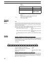
Alarm List (Bit Memory Table) (page 173)
Allocation destination: Bit
PT
PC
Material low
010009
1
Character string memory table 120
Alarm list
Material low
Bit memory table 23
Bit 010009
Character string memory table 120
When the PC bit comes ON (1), the contents of the character string memory
tables registered for the bit memory tables are displayed in the alarm list. When
the bit returns to the OFF (0) status, the character string memory table display is
automatically cleared.
Alarm History (Bit Memory Table) (page 173)
Allocation destination: Bit
PT
PC
Water temp. high
015012
Alarm history
Character string memory table 134
Water temp. high
Bit memory table 52
Bit 015012
Character string memory table 134
Alarm history record data
26
1
Section
Communications with the Host
1-4
The PC bit allocated to bit memory table for which the history property has been
set is continually monitored: when the bit comes ON (1), the time and the number
of times, and the contents of the character string memory table registered for the
bit memory table, are recorded in the alarm history record data.
This record data can be displayed as the alarm history.
PT Status Control Area
(PC ↔ PT)
The PT status control area is used to control the PT status. When data is written
to this area in the PC, the PT reads the contents and operates according to the
contents.
Example of PT Status Control Area Application
When data is written to the PT status control area, the PT operates as shown
below (page 46).
PC
PT
Screen 3 display
PT status control area
0003
0050
1007
A000
Continuous
buzzer
sound
Screen switch setting
Memory table
Copy setting
PT status control bits
System reserve
Numeral memory table 50
Copy
PT Status Notify Area
(PT to PC)
Numeral memory table 7
The PT status notify area is used to notify the changes in the PT status.
When the PT status changes, the change is written to this area in the PC. By
reading the data from this area, the PT status can be checked.
Example of PT Status Notify Area Application
When the PT status changes, the change is applied to the PT status notify area
as shown below (page 55).
PT
PC
Numeral memory table 13
12345678
12345678
PT status notify area
0013
8800
7 8 9
4 5 6
1 2 3
0.
Content upgrade memory table
PT status
Allocated word (numeral table 13)
12345678
5
1
6
2
7
3
8
4
Start
Start + 1
Reference: When the PT is set to NT30/620 compatible mode, the word configuration is identical to that of the earlier NT30, NT30C, NT620S, NT620C, and NT625C PTs.
Functions of the Window
Control Area
(PC to and from PT)
The window control area is used to notify and control the window status. The
window control area has areas that correspond to three windows. Each area
stores the screen number, and the X and Y coordinates of the lower left corner of
the window that is being displayed.
When data is written to this area in the PC, the PT reads the contents and executes tasks such as switching the windows to be displayed or moving the position of the windows according to the contents (page 232).
When the window display status changes, the change is written to this area in
the PC. By reading the data from this area, the window display status can be
checked (refer to page 232).
If the window functions are not used, it is not necessary to allocate a window control area to the host.
27
Section
Communications with the Host
1-4
Example of Window Control Area Application
When data is written to the window control area, the PT operates as shown below.
PT
PC
WIndow control area
(local window 2)
0034
0020
0139
Window
(screen No.34)
Opens
Screen number
X coordinate
Y coordinate
Bottom left coordinate
(20, 139)
When the window display status changes, the change is notified to the window
control area as shown below (Window’s Opening/Closing status is notified to the
PT status notify area as well).
PT
PC
WIndow
PT
statuscontrol
notify area
(local window 2)
Move
Window
(screen No.34)
0034
0180
0219
Screen No.
X coordinate
Y coordinate
Bottom left coordinate
(180, 219)
1-4-5 Connecting to other Companies’ PCs
Installing a system program for multi-venders by using a specific system installer
enables the NT31/NT31C or NT631/NT631C to be connected to the PCs of other companies in direct connection. This system installer is supplied with the Support Tool (NT-ZJCAT1-EV4).
Compatible PCs
28
The NT31/NT31C and NT631/NT631C can be connected to the following Mitsubishi PCs.
• Mitsubishi A series programmable controller (computer link module)
• Mitsubishi FX series programmable controller
For details on the procedure for connecting to other model PCs, refer to the PC
Connection Manual.
Section
Communication by Using Memory Link
1-5
1-5
Communication by Using Memory Link
In this section, a communication method other than the direct connection, called
the memory link, is discussed.
1-5-1 Memory Link
The memory link is a method to send and receive data between a personal computer or a FA computer and the PT by using RS-232C/422A communication.
In memory link, there is an area called the PT Memory, as shown below, inside
the PT, and this area is treated as a virtual area on the PC. This allows PT
memory and the display elements of the PT to make a quasi-direct connection.
By sending a command for the memory link, the host can make the PT execute
processes through PT memory. Frequently used commands are kept handy for
read and write tasks of the numeral memory table, character-string memory
table, and bit memory table.
NT31/NT31C
PT
PC
PT memory
Numeral
memory
table
Lamp
Direct connection
RS-232C/422A
communication
In the memory link method, the only difference is that the PT finds its communication target inside instead of outside. In the memory link method, therefore,
change of the target is all that is needed to be capable of using the exact screen
data that is acquired by the direct connection. (With the NT31/NT31C and
NT631/NT631C, the Support Tool must be used to convert the data to screen
data for the memory link.)
When compared to the direct connection of the host link or NT Link methods, the
memory link method has some restrictions regarding the use of some functions,
as described below.
• The Programming Console and Device Monitor functions cannot be used.
• The following strobes of PT status notify bits do not turn ON (page 7 to 27).
Screen switching strobe
Numerals input strobe
Character-string input strobe
• The usable area for allocation is the PT memory only.
1-5-2 Comparison between Direct Connection and Memory Link
The major differences between the direct connection and the memory link are as
follows:
• In the memory link method, the communication with the host should be carried
out by using commands. Compared to the ordinal direct connection, which can
be used requiring almost no programs, the memory link method requires a program that is necessary for interchange of commands. This, however, gives advantages to the memory link method by using a large variety of functions available in the direct connections from major models such as a personal computer
and a FA computer equipped with RS-232C/RS-422A communication means,
allowing the PT to be suited for larger usage.
29
Communication by Using Memory Link
Section
1-5
• Actual PCs have many kinds of areas, where as PT memory is a single area
with only one kind. When creating screen data by using the memory link methods, it is always necessary to allocate display parts in the PT memory.
For communication between the host and the PT by the memory link method,
refer to Section 4 Using Memory Link, and for how to use screen and display
elements, refer to Section 3 How to Use the PT.
1-5-3 Memory Link Online Transfer Function
When memory link communications are being used, the PT can be switched to
Transmit mode from the host and screen data can be written even if the PT is
operating. (The PT can be returned to RUN mode after the screen data is written.)
The memory link online transfer function can be used to replace screen data at a
fixed time each day or replace screen data with maintenance screen data for
maintenance.
For more details on the memory link online transfer function, refer to 4-4 Memory
Link Online Transfer Function.
30
Section
Before Operating
1-6
1-6
Before Operating
Follow the procedure given below to start the system of the NT31/NT31C or
NT631/NT631C.
Host
NT31/NT31C or
NT631/NT631C
Support Tool
Set the host settings.
Install the PT in the
operation panel.
Install the Support
Tool at the computer.
(refer to the manual for
the Support Tool)
Connect the power supply.
Install the system program.*1
Make the settings in the
system installer mode.*2
Create the screens.
(refer to Sections
2through 5 and the
Support Tool manual)
Transmit the screen data.
Set the memory switches.
Connect to the
NT31/NT31C or
NT631/NT631C.
Connect to the host.
Create the host program.
Confirm the settings and
check communication.
Start operation.
*1: System program installation is only done in special circumstances, for example
when changing the system program, or to recover the original status of the
installed program. This operation is not normally necessary. When using other PC
models (sequencers), however, it is necessary to install specific system programs.
*2: Display of the system menu, and all change operations, can be disabled to prevent
the accidental deletion or alteration of screens and settings.
Reference:
For the system program, use the NT31/NT31C or NT631/NT631C system
program supplied as an accessory with the NT series Support Tool (NTZJCAT1-EV4).
For the Support Tool, use NT-series Support Tool for Windows 95/98 (Ver. 4.1).
Refer to the following manuals for the Units and software.
31
Section
Before Operating
Equipment or Software
Manual Title
Manual Number
NT31/NT31C
Setup Manual
V062-E1-
NT631/NT631C
Setup Manual
V063-E1-
System Installer
NT-series Support Tool for Windows95/98 (Version 4.1)
V061-E1-
Support Tool
NT-series Support Tool for Windows95/98 (Version 4.1)
V061-E1-
PC
SYSMAC CPM1 Operation Manual
W262-E1-
SYSMAC CPM1A Operation Manual
W317-E1-
SYSMAC CPM2A Operation Manual
W352-E1-
SYSMAC CPM2C Operation Manual
W356-E1-
SYSMAC C200H Operation Manual (for CPU01/03/11) (programming)
W130-E1-
SYSMAC C200H Operation Manual (for CPU21/23/31) (programming)
W217-E1-
SYSMAC C200HS Installation Guide
W236-E1-
SYSMAC C200HS Operation Manual (programming)
W235-E1-
SYSMAC C200HX/HG/HE(-Z) Installation Guide
W302-E1-
SYSMAC C200HX/HG/HE Programming Manual
W303-E1-
SYSMAC C200HX/HG/HE-Z Programming Manual
W322-E1-
SYSMAC C1000H/C2000H Operation Manual (programming)
W140-E1-
SYSMAC CQM1 Programming Manual
W228-E1-
SYSMAC CQM1H Operation Manual
W363-E1-
SYSMAC CVM1/CV500/CV1000/CV2000 Operation Manual: Ladder
Diagrams
W202-E1-
CS1-series CS1G/H-CPU -EV1 Programmable Controllers Operation Manual
W339-E1-
CS1-series Serial Communication Boards/Units Operation Manual
W336-E1-
SYSMAC CQM1H Series Serial Communications Board Operation
Manual
W365-E1-
CompoBus master control
unit
SRM1 Operation Manual
W318-E1-
Peripheral tools
SYSMAC Support Software Operation Manual: C-series PCs
W248-E1-
SYSMAC Support Software Operation Manual: CVM1 PCs
W249-E1-
SYSMAC CPT Operation Manual
W332-E1-
W333-E1-
CX-Programmer Operation Manual
Host link unit/
Communication Board
32
1-6
-
SYSMAC C series Host Link Unit Operation Manual
W143-E1-
SYSMAC CVM1/CV Series Host Link Operation Manual
W205-E1-
SYSMAC
C200HW-COM01 C200HW-COM02-V1 to C200HW-COM06-EV1
Communications Boards Operation Manual
W304-E1-
SECTION 2
PT Functions
This section describes the functions of the PT.
2-1
2-2
2-3
2-4
2-5
2-6
2-7
2-8
2-9
2-10
2-11
2-12
2-13
2-14
PT Screens . . . . . . . . . . . . . . . . . . . . . . . . . . . . . . . . . . . . . . . . . . . . . . . . . . . . . . . . . . . . . .
2-1-1 Screen Composition . . . . . . . . . . . . . . . . . . . . . . . . . . . . . . . . . . . . . . . . . . . . . . . .
2-1-2 Screen Numbers . . . . . . . . . . . . . . . . . . . . . . . . . . . . . . . . . . . . . . . . . . . . . . . . . . .
2-1-3 Screen Types . . . . . . . . . . . . . . . . . . . . . . . . . . . . . . . . . . . . . . . . . . . . . . . . . . . . .
2-1-4 Screen Attributes . . . . . . . . . . . . . . . . . . . . . . . . . . . . . . . . . . . . . . . . . . . . . . . . . .
2-1-5 Display Colors . . . . . . . . . . . . . . . . . . . . . . . . . . . . . . . . . . . . . . . . . . . . . . . . . . . .
2-1-6 Display Elements . . . . . . . . . . . . . . . . . . . . . . . . . . . . . . . . . . . . . . . . . . . . . . . . . .
Areas for Control/Notification . . . . . . . . . . . . . . . . . . . . . . . . . . . . . . . . . . . . . . . . . . . . . . .
2-2-1 PT Status Control Area (Host ↔ PT) . . . . . . . . . . . . . . . . . . . . . . . . . . . . . . . . . .
2-2-2 PT Status Notify Area (PT to Host) . . . . . . . . . . . . . . . . . . . . . . . . . . . . . . . . . . . .
2-2-3 Window Control Area (Host ↔ PT) . . . . . . . . . . . . . . . . . . . . . . . . . . . . . . . . . . .
Memory Tables . . . . . . . . . . . . . . . . . . . . . . . . . . . . . . . . . . . . . . . . . . . . . . . . . . . . . . . . . . .
2-3-1 Numeral Memory Tables . . . . . . . . . . . . . . . . . . . . . . . . . . . . . . . . . . . . . . . . . . . .
2-3-2 Character String Memory Tables . . . . . . . . . . . . . . . . . . . . . . . . . . . . . . . . . . . . . .
2-3-3 Bit Memory Tables . . . . . . . . . . . . . . . . . . . . . . . . . . . . . . . . . . . . . . . . . . . . . . . .
Fixed Displays . . . . . . . . . . . . . . . . . . . . . . . . . . . . . . . . . . . . . . . . . . . . . . . . . . . . . . . . . . .
2-4-1 Circles, Arcs, Sectors, Polylines, Polygons, Rectangles
(Fixed Displays) . . . . . . . . . . . . . . . . . . . . . . . . . . . . . . . . . . . . . . . . . . . . . . . . . . .
2-4-2 Text (Fixed Display) . . . . . . . . . . . . . . . . . . . . . . . . . . . . . . . . . . . . . . . . . . . . . . .
2-4-3 Tiling . . . . . . . . . . . . . . . . . . . . . . . . . . . . . . . . . . . . . . . . . . . . . . . . . . . . . . . . . . .
2-4-4 Marks . . . . . . . . . . . . . . . . . . . . . . . . . . . . . . . . . . . . . . . . . . . . . . . . . . . . . . . . . . .
Image and Library Data . . . . . . . . . . . . . . . . . . . . . . . . . . . . . . . . . . . . . . . . . . . . . . . . . . . .
2-5-1 Image Data Display . . . . . . . . . . . . . . . . . . . . . . . . . . . . . . . . . . . . . . . . . . . . . . . .
2-5-2 Library Data Display . . . . . . . . . . . . . . . . . . . . . . . . . . . . . . . . . . . . . . . . . . . . . . .
Lamps . . . . . . . . . . . . . . . . . . . . . . . . . . . . . . . . . . . . . . . . . . . . . . . . . . . . . . . . . . . . . . . . . .
Touch Switches . . . . . . . . . . . . . . . . . . . . . . . . . . . . . . . . . . . . . . . . . . . . . . . . . . . . . . . . . .
Numeral Display . . . . . . . . . . . . . . . . . . . . . . . . . . . . . . . . . . . . . . . . . . . . . . . . . . . . . . . . .
Character String Display . . . . . . . . . . . . . . . . . . . . . . . . . . . . . . . . . . . . . . . . . . . . . . . . . . .
Graphs . . . . . . . . . . . . . . . . . . . . . . . . . . . . . . . . . . . . . . . . . . . . . . . . . . . . . . . . . . . . . . . . .
2-10-1 Bar Graphs . . . . . . . . . . . . . . . . . . . . . . . . . . . . . . . . . . . . . . . . . . . . . . . . . . . . . . .
2-10-2 Analogue Meter . . . . . . . . . . . . . . . . . . . . . . . . . . . . . . . . . . . . . . . . . . . . . . . . . . .
2-10-3 Broken Line Graphs . . . . . . . . . . . . . . . . . . . . . . . . . . . . . . . . . . . . . . . . . . . . . . . .
2-10-4 Trend Graphs . . . . . . . . . . . . . . . . . . . . . . . . . . . . . . . . . . . . . . . . . . . . . . . . . . . . .
Alarm List, Alarm History . . . . . . . . . . . . . . . . . . . . . . . . . . . . . . . . . . . . . . . . . . . . . . . . . .
Inputting Numeric Values . . . . . . . . . . . . . . . . . . . . . . . . . . . . . . . . . . . . . . . . . . . . . . . . . . .
2-12-1 Numeric Key Type (Numeral Input) . . . . . . . . . . . . . . . . . . . . . . . . . . . . . . . . . . .
2-12-2 Thumbwheel Type (Thumbwheel) . . . . . . . . . . . . . . . . . . . . . . . . . . . . . . . . . . . . .
Inputting Character Strings . . . . . . . . . . . . . . . . . . . . . . . . . . . . . . . . . . . . . . . . . . . . . . . . .
Recipe . . . . . . . . . . . . . . . . . . . . . . . . . . . . . . . . . . . . . . . . . . . . . . . . . . . . . . . . . . . . . . . . . .
2-14-1 Function Outline . . . . . . . . . . . . . . . . . . . . . . . . . . . . . . . . . . . . . . . . . . . . . . . . . .
2-14-2 Operation Outline . . . . . . . . . . . . . . . . . . . . . . . . . . . . . . . . . . . . . . . . . . . . . . . . .
2-14-3 Limits . . . . . . . . . . . . . . . . . . . . . . . . . . . . . . . . . . . . . . . . . . . . . . . . . . . . . . . . . . .
2-14-4 Common Attributes . . . . . . . . . . . . . . . . . . . . . . . . . . . . . . . . . . . . . . . . . . . . . . . .
2-14-5 Display Functions . . . . . . . . . . . . . . . . . . . . . . . . . . . . . . . . . . . . . . . . . . . . . . . . .
2-14-6 Input Functions . . . . . . . . . . . . . . . . . . . . . . . . . . . . . . . . . . . . . . . . . . . . . . . . . . .
2-14-7 Output Functions . . . . . . . . . . . . . . . . . . . . . . . . . . . . . . . . . . . . . . . . . . . . . . . . . .
2-14-8 Relationship with Other Elements . . . . . . . . . . . . . . . . . . . . . . . . . . . . . . . . . . . . .
35
35
35
35
39
41
43
46
46
55
59
64
64
71
75
81
81
89
92
94
97
97
100
103
110
130
138
144
144
148
154
161
173
183
183
191
201
207
207
211
217
217
226
226
226
226
33
Section
2-15 Window Function . . . . . . . . . . . . . . . . . . . . . . . . . . . . . . . . . . . . . . . . . . . . . . . . . . . . . . . . .
2-15-1 What are windows? . . . . . . . . . . . . . . . . . . . . . . . . . . . . . . . . . . . . . . . . . . . . . . . .
2-15-2 Window Type . . . . . . . . . . . . . . . . . . . . . . . . . . . . . . . . . . . . . . . . . . . . . . . . . . . . .
2-15-3 Window Screens and Display Elements . . . . . . . . . . . . . . . . . . . . . . . . . . . . . . . .
2-15-4 Opening/Closing and moving a window . . . . . . . . . . . . . . . . . . . . . . . . . . . . . . . .
2-15-5 Size and display position of a window . . . . . . . . . . . . . . . . . . . . . . . . . . . . . . . . .
2-15-6 Changing the displaying order of windows . . . . . . . . . . . . . . . . . . . . . . . . . . . . . .
2-15-7 Checking the display status of a window . . . . . . . . . . . . . . . . . . . . . . . . . . . . . . . .
2-15-8 Temporary Input Fields . . . . . . . . . . . . . . . . . . . . . . . . . . . . . . . . . . . . . . . . . . . . .
2-15-9 Focus window . . . . . . . . . . . . . . . . . . . . . . . . . . . . . . . . . . . . . . . . . . . . . . . . . . . .
2-16 Special Functions . . . . . . . . . . . . . . . . . . . . . . . . . . . . . . . . . . . . . . . . . . . . . . . . . . . . . . . . .
2-16-1 Display History Record Function . . . . . . . . . . . . . . . . . . . . . . . . . . . . . . . . . . . . .
2-16-2 Alarm History Record Function . . . . . . . . . . . . . . . . . . . . . . . . . . . . . . . . . . . . . .
2-16-3 Resume Function . . . . . . . . . . . . . . . . . . . . . . . . . . . . . . . . . . . . . . . . . . . . . . . . . .
2-16-4 Screen Saver Function . . . . . . . . . . . . . . . . . . . . . . . . . . . . . . . . . . . . . . . . . . . . . .
2-16-5 Buzzer Function . . . . . . . . . . . . . . . . . . . . . . . . . . . . . . . . . . . . . . . . . . . . . . . . . . .
2-16-6 Clock Function . . . . . . . . . . . . . . . . . . . . . . . . . . . . . . . . . . . . . . . . . . . . . . . . . . . .
2-16-7 Print Function . . . . . . . . . . . . . . . . . . . . . . . . . . . . . . . . . . . . . . . . . . . . . . . . . . . .
2-16-8 Adjusting Contrast and Brightness During PT Operation . . . . . . . . . . . . . . . . . . .
2-16-9 Programming Console Function . . . . . . . . . . . . . . . . . . . . . . . . . . . . . . . . . . . . . .
2-17 Device Monitor Function . . . . . . . . . . . . . . . . . . . . . . . . . . . . . . . . . . . . . . . . . . . . . . . . . . .
2-17-1 Compatible Systems . . . . . . . . . . . . . . . . . . . . . . . . . . . . . . . . . . . . . . . . . . . . . . .
2-17-2 Device Monitor Screens and Functions . . . . . . . . . . . . . . . . . . . . . . . . . . . . . . . . .
2-17-3 Starting and Exiting Device Monitor . . . . . . . . . . . . . . . . . . . . . . . . . . . . . . . . . . .
2-17-4 Operations Common to the Device Monitor Screens . . . . . . . . . . . . . . . . . . . . . .
2-17-5 Using the Registration Monitor Screen . . . . . . . . . . . . . . . . . . . . . . . . . . . . . . . . .
2-17-6 Using the Continuous Monitor Screen . . . . . . . . . . . . . . . . . . . . . . . . . . . . . . . . . .
2-17-7 Using the Error Log Screen . . . . . . . . . . . . . . . . . . . . . . . . . . . . . . . . . . . . . . . . . .
2-17-8 Errors Occurring during Device Monitor Operation . . . . . . . . . . . . . . . . . . . . . . .
2-18 Mathematical Function . . . . . . . . . . . . . . . . . . . . . . . . . . . . . . . . . . . . . . . . . . . . . . . . . . . . .
2-18-1 Executable Calculations . . . . . . . . . . . . . . . . . . . . . . . . . . . . . . . . . . . . . . . . . . . . .
2-18-2 Data Flow in Calculations . . . . . . . . . . . . . . . . . . . . . . . . . . . . . . . . . . . . . . . . . . .
2-18-3 Precautions When Using the Mathematical Function . . . . . . . . . . . . . . . . . . . . . .
2-19 PT Configuration Settings . . . . . . . . . . . . . . . . . . . . . . . . . . . . . . . . . . . . . . . . . . . . . . . . . .
2-19-1 PT Configuration Settings . . . . . . . . . . . . . . . . . . . . . . . . . . . . . . . . . . . . . . . . . . .
34
228
228
229
230
230
231
232
233
233
233
235
235
237
240
240
241
242
243
246
248
250
250
251
251
253
254
261
264
267
269
269
272
273
275
275
Section
PT Screens
2-1
2-1
PT Screens
This section describes the PT screens, which are the basis of PT functions.
2-1-1 Screen Composition
The size of the NT31/NT31C and NT631/NT631C screens are as follows:
NT31/NT31C:
320 dots wide by 240 dots high
NT631/NT631C:
640 dots wide by 480 dots high
The location of each dot is expressed by Cartesian coordinates: an X coordinate
(horizontal direction) and a Y coordinate (vertical direction). The coordinate origin (0, 0) is at the top left of the screen.
NT31/NT31C
0
X coordinate (horizontal direction)
NT631/NT631C
319
0
X coordinate (horizontal direction)
639
0
Coordinates (X, Y)
239
Y coordinate (vertical direction)
Y coordinate (vertical direction)
0
319,239
479
Coordinates (X, Y)
639,479
2-1-2 Screen Numbers
The screens of the PT are classified and managed by screen numbers.
Screen numbers are used to designate the first screen displayed when the PT is
started up, and to designate the objective screen when switching the screen display, etc.
The PT allows up to 3999 screens to be registered, apart from those screens
reserved for specific functions. For these 3999 screens, screen numbers can be
designated without restriction within the range 1 to 3999. There are also no restrictions on the order of screen numbers, they can be discontinuous either.
When creating a screen at the PT with the Support Tool, designate a screen
number and then register the display elements.
2-1-3 Screen Types
The screens that can be displayed by the PT are classified as follows according
to their function.
• Normal (Standard) screens
• Overlapping screens
• Window screens
• System screens
Normal (Standard)
Screens
Normal (Standard) screens are the basic screens of the PT. There are no specific functions themselves and their purpose is to display elements that have already been registered.
35
Section
PT Screens
2-1
Normal (Standard) screens can be registered under any screen numbers in the
range 1 to 3999.
Overlapping Screens
The PT allows up to 8 screens to be displayed overlapped as one screen. A
group of overlapped screens is called an overlapping screen.
To allow distinction, the screen that results when the multiple component
screens are overlapped is called the parent screen. and the individual component screens are called the child screens.
Both parent screens and child screens can be registered under any screen numbers in the range 1 to 3999. Note that a new screen must be designated as a
parent screen.
[Parent screen]
[Child screen]
Screen No. 10
This is an
Screen No. 8
Screen No. 7
This is an
overlapping
screen.
overlapping
Screen No. 25
screen.
Child Screen Registration and Display Result
Child screens are created as normal (standard) screens. Therefore they can
also be displayed independently by designating their screen numbers.
Parent screens are special screens used for the purpose of displaying overlapping screens. They are created by designating a new screen as a parent screen
at the Support Tool. Register only the screen numbers of the child screens to be
overlapped for this new screen. Direct registration of elements on a parent
screen is not possible.
To display an overlapping screen on the PT, designate the screen number of the
parent screen. The child screens will be displayed in the order they were registered (i.e., the first one registered will be the bottom-most screen) to build up the
compound image.
Note that the order in which the child screens are registered may affect the way
that overlapped screens are displayed.
36
Child screen 1
Registration order:
Child screen 1 → Child screen 2
Child screen 2
Registration order:
Child screen 2 → Child screen 1
Section
PT Screens
2-1
tRestrictions On Overlapping Screens
Note the following points, when creating an overlapping screen.
• Numeral input and character string input input fields — which allow the input of
numeric values and character strings — can each only be set on one of the
child screens. (Thumbwheel switches can be used but temporary input fields
cannot.) For details on numeral input, refer to 2-12 Inputting Numeric Values
(page 183), and for details on character string input, refer to 2-13 Inputting
Character Strings (page 201).
• Arrange the touch switches registered for each child screen, so that they do not
overlap on the parent screen. If touch switches are overlapped, the intended
operation may not be performed when a touch switch is pressed.
• On an overlapping screen, the screen attributes of the child screens are invalid
and the screen display is governed by the attributes of the parent screen. For
details on screen attributes, refer to 2-1-4 Screen Attributes (page 39).
Window Screens
Apart from the normal (standard) screen display method, which a screen is displayed over the entire panel area, the PT also allows screens to be displayed in
one part of the screen area only. This partial screen is called a window. and a
screen on which a window is displayed is called a window screen.
Window screens can be registered under any screen numbers 1 to 3999. However, screens that are registered as window screens cannot be displayed independently like normal (standard) screens.
Base screen
Keypad
Keypad
Touch switch for opening
the window
7 8 9
4 5 6 .
1 2 3 0
Window displayed on the screen
at the registered size and position
Window screen
7 8 9 4 5 6 .
1 2 3 0
Window area
Windows can be called anytime, regardless of which screen is currently displayed. It is possible to display multiple windows (max : 3) on the same screen,
and to open, close or move windows by the control from the host.
With PT, up to three windows can be displayed at the same time.
One of these windows is called a global window. This window can be displayed
all the time, regardless of which screen is currently displayed.
Other two windows are called local windows. These windows can be displayed
by linking to the currently displayed screens. When the screen is switched, the
local window is closed automatically.
For details, refer to 2-15 Window Function (page 228 ).
37
Section
PT Screens
Screens with predetermined functions are called system screens.
The types of system screens are indicated in the table below.
System Screens
Screen
No.
2-1
Name
Function
0
No-display screen
If screen number 0 is designated as the display screen, the screen of the PT is made
blank.
9000
System initializing
screen
This screen is displayed during the initial processing when the PT starts operation.
During operation, screen number 9000 cannot be designated for display, but it is possible to create and register a screen under screen number 9000 at the Support Tool,
and this screen can then be displayed instead of the default system initialization
screen. Only fixed display elements can be registered for screen number 9000.
9001
Occurrence history
screen
The PT features the display history record function. which records the display status
of screens. By designating screen number 9001 as the display screen, you can
check the screens that have been displayed up to the present time in display order.
You can set whether the records are presented in the order of newest first or oldest
first by setting a PT memory switch.
9002
Frequency history
screen
The PT features the display history record function. which records the display status
of screens. By designating screen number 9002 as the display screen, you can
check the screens that have been displayed up to the present time in order of frequency of display.
9020
Programming Console function
screen
As an expansion function, the PT features the Programming Console function, which
allows equivalent functions to those of a Programming Console. When the PT is connected to a host which supports the Programming Console function, it can be used in
the place of a Programming Console by designating screen number 9020 as the display screen.
9021 to
9023
Device Monitor
function screens
The PT has been equipped with the Device Monitor function, which can perform the
same functions as a Data Access Console (DAC). When the PT is connected to a
host that supports the Device Monitor function, one of the following screens can be
specified to list the contents of host words, change word PVs, or display error log
information.
9021:
Registration monitor screen
9022:
Continuous monitor screen
9023:
Error log screen
9030
Brightness and
Contrast Adjustment Screen
This screen can be used to adjust the contrast and the backlight brightness during
PT operation.
9999
Return to previous
screen designation
In addition to the display history function, the PT has a function which allows the
screen numbers of up to 32 screens to be recorded in their order of display. When
screen number 9999 is designated as the display screen, the screen that was displayed immediately before the currently displayed screen is redisplayed. However,
note that if a system screen is displayed in the middle of operation, the record of displayed screens is cleared. (The display history function’s data is not affected.)
For details on the display history function, refer to 2-16-1 Display History Record
Function (page 235).
For details on the Programming Console function, refer to 6-12 Programming
Console Function of the Setup Manual (V062-E1-).
For details on the Device Monitor function, refer to 2-17 Device Monitor Function
(page 250).
For details on screen switching refer to 3-3-1 Switching the Screen (page 289).
38
Section
PT Screens
2-1
2-1-4 Screen Attributes
The PT allows attributes to be set for each screen, so that the function specified
by the attribute is executed when the screen is displayed. For example, when a
screen for which the buzzer attribute has been set is displayed, the buzzer
sounds.
Set the screen attributes as properties of each screen using the Support Tool.
The screen attributes that can be set are listed below. It is possible to set more
than one attribute for the same screen at one time.
• Backlight (Light/Flash)
• Buzzer (None/Continuous/Long/Short)
• Background (NT31C and NT631C only)
• Screen comment
• History (record/don’t record)
• History title
• Load Local1 (Keyboard) (screen number)
• Load Local2 (screen number)
Backlight
The backlight attribute sets whether the backlight is lit or flashed when a screen
is displayed.
Setting
Function
Light
The backlight is lit. (Default)
Flash
The backlight is flashed.
Reference: The PT’s backlight can also be lit or made to flash using the PT status control bit
(page 283).
Buzzer
The buzzer attribute allows the buzzer to sound when a screen is displayed.
There are the following four types of buzzer attribute setting.
Setting
None
Function
The buzzer does not sound when the screen is displayed. (Default)
If the buzzer is sounding when the screen is displayed, it stops.
The buzzer sounds continuously when the screen is displayed.
Continuous If a buzzer type other than continuous is sounding when the screen is
displayed, the sound changes to continuous.
Long
The long intermittent buzzer sounds when the screen is displayed.
If a buzzer type other than long intermittent is sounding when the
screen is displayed, the sound changes to long intermittent.
The long intermittent buzzer sound is the repeated alternation of 1.0
second on and 1.0 second off.
Short
The short intermittent buzzer sounds when the screen is displayed.
If a buzzer type other than short intermittent is sounding when the
screen is displayed, the sound changes to short intermittent.
The short intermittent buzzer sound is the repeated alternation of 0.5
seconds on and 0.5 seconds off.
39
Section
PT Screens
2-1
The setting for the Buzzer Sound memory switch at the PT takes priority in determining whether or not the buzzer actually sounds. When this memory switch is
set to ON. the buzzer set with a screen attribute can sound.
Reference:
The buzzer can also sound by PT status control bit operation (page 280).
The following methods can be used to stop the buzzer when it is sounding.
• Switching to a screen whose buzzer attribute is None
• Stopping the buzzer by PT status control bit operation (page 282)
• Registering the buzzer stop touch switch on the screen (page 283)
Background Color (NT31C and NT631C Only)
With the NT31C and NT631C, the background color of the entire screen can be
set for each screen. The following 8 background colors can be set.
Black, blue, red, magenta, green, cyan, yellow, white
Screen Comment
A comment indicating the contents of the screen can be set as any required
character string of up to 24 characters.
History
When a screen for which this attribute is set is displayed, the screen number,
display time, number of times displayed, and history title of the displayed screen
are recorded as display history data.
Setting
Function
Checked
When the screen is displayed, its data is recorded in the display history.
Not
checked
When the screen is displayed, its data is not recorded in the display
history. (Default)
Reference: The display history can be checked in the Maintenance mode of the PT, and can
also be read during operation by displaying screen number 9001 (occurrence order) or screen number 9002 (frequency order). It is also possible to transmit the
display history record data to the personal computer by operation at the Support
Tool. For details, refer to the NT-series Support Tool Version 4.0 for Windows Operation Manual.
History Title
This attribute sets a character string to be recorded in the display history along
with the display time and other information when a screen for which the history
attribute is set is displayed.
The history title can be set as any required character string of up to 24 characters.
This setting is only valid for screens for which the history attribute is set. When a
screen for which the history title attribute is set is displayed by the PT, the designated character string is recorded together with the screen number in the display
history.
Load Local1, Load Local2
Specify whether or not a window (Local1, Local2) pops up at the same time the
screen is displayed by screen switching. Set the window screen number to be
displayed when you check these attribute.
For details of a window, refer to 2-15 Window Function (page 228), and for details of using method of a window, refer to 3-4 Display and Control of Windows
(page 298)
40
Section
PT Screens
Reference:
2-1
A window can also be opened, closed or moved by the operation at Window
control area. (Refer to page 301.)
To control (open close or move) a window, follow the methods below.
• Register an Input key-Window/Keyboard touch switch or a Window Move
touch switch on a screen. (Refer to pages 299, 300.)
• Register a Cursor Move touch switch which has a window open function.
(Refer to page 299.)
• Operate Window control area from the host. (Refer to page 301.)
• Switch to the screen which has a Load Local1 (keyboard) or Load Local2
screen attribute. (Refer to page 302.)
Restrictions Relating to
Screen Attributes
The functions of the backlight and buzzer attributes can also be performed using
the PT status control bits. (And the buzzer can also be operated with a touch
switch.) When a screen for which one of these attributes is set is displayed, the
set function is executed regardless of the status of the PT status control bits, but
the status of the backlight or buzzer can be changed later by using another operation.
Depending on the screen attribute settings and the PT status control bit statuses, the PT status control bit statuses may not match the actual operation (ex.
the buzzer bit in the PT status control bits may indicate that the buzzer is stopped
although the buzzer is actually sounding). In such a case, carry out PT status
control bit operations to make the statuses agree with the actual status of the PT.
For details on the PT status control bits, refer to 2-2-1 PT Status Control Area
(page 46).
2-1-5 Display Colors
When a screen is created with the Support Tool, the color of each element displayed on the PT screen can be set in the element’s attributes.
Available Colors
The monochrome PTs (NT31 and NT631) can display elements in black or
white. (The NT631 has an EL display so lit elements will actually appear orange,
but the color is still referred to as white.)
The color PTs (NT31C and NT631C) can display the following eight colors.
Black, blue, red, magenta, green, cyan, yellow, white
When an element’s color is the same as the background color (making it invisible), the PT changes the color of the element to its opposite color to make it visible. The opposite color combinations (XOR relationships) are as follows:
Black ⇔ White, Blue ⇔ Yellow, Red ⇔ Cyan, Magenta ⇔ Green
The following kinds of display elements are displayed in the above combinations
of colors.
• Frame of input fields for numeral/character string input, and screen background color (page 183, 201).
• Display color of eight dots beyond the top of a bar graph, and screen background color (page 147).
Reference: XOR is the abbreviation of eXclusive OR. Color combinations that are opposites
in terms of the three primary colors — red, green, and blue — are said to be in an
XOR relationship.
Example: Blue (red 0, blue 1, green 0) ⇔ Yellow (red 1, blue 0, green 1)
41
Section
PT Screens
2-1
Color Correspondence Between Color and Monochrome PTs
The only colors that a monochrome PT can display are white and black.
The screen data for a color PT can be displayed on a monochrome PT without
alteration and in this case the color correspondences are as follows.
Color on a color PT
Color on an NT31
Color on an NT631
Black, blue, red, or magenta
White
Black
Green, cyan, yellow, or white
Black
White (EL lit color)
Likewise, the screen data for a monochrome PT can be displayed on a color PT
without alteration and in this case the color correspondences are as follows.
Color on an NT31
Color on an NT631
Color on a color PT
White
Black
Black
Black
White (EL lit color)
White
Reference: When screen data is created for an NT31, black and white are displayed as white
and black respectively at the Support Tool.
Transparent Display
When elements are displayed on top of others, normally the background color of
the element on top conceals the element below so that it cannot be seen.
Besides the above eight colors, the color transparent is available for the background of some display elements.
When transparent is set, nothing appears behind a display element, and the display element or screen background color underneath it is visible.
<Normal display>
<Transparent display>
Graphic under character
A
Character
Background
color
Graphic under character
A
Character
Background color
(transparent)
Possible Applications of The Transparent Color Designation
• Background color of normal display text
• Background of labels for lamps and touch switches (fixed as transparent)
• Display color of lamps and touch switches when they are off
• Background color of tiling patterns for graphics
• Background color of marks
Impossible Applications of The Color Transparent Designation
• Background of character strings displayed from character string memory
tables
• Background of numeric values displayed from numeral memory tables
• Background of numeric values and character strings in numeral setting input
fields and character string input fields
• Background of characters indicating percentages (%) on graphs
• Display color of lamps and touch switches when lit
• Background color of temporary input fields
42
Section
PT Screens
2-1
• Display color of alarm list/history
Screen Background
Color
The background color of the entire screen can be designated with the Background screen attribute. Screen attributes are properties set for each screen
with the Support Tool.
Text Display Color
The color of characters (character color) and that of their rectangular frames
(background color) can be specified.
A
Graphics Display Color
Background color
Character color
The colors of lines and tiling patterns can be specified for graphics.
The colors that can be designated for tiling patterns are the color of the pattern
itself, the background color of the pattern, and the color of the outline of the tiled
area.
Outline color (Border)
Pattern display
color (Foreground)
Tiling
Pattern background
color (Background)
Line color
Reference: When a lamp, a touch switch, and a graphic are displayed in color, part of the
frames of the display elements may be invisible because of the combination of
the background, outline, and tiling colors. This is a phenomenon peculiar to a color LCD, not a failure of the system. In such a case, change the color combination.
2-1-6 Display Elements
The PT can display the following elements.
Mark
Text
95/04/10 14:10
LINE B PRODUCTION
STATUS
Image data
EMERGENCY
STOP
Graphic
Touch switch
Lamp
OUTPUT TARGET
Character strings
PRODUCT
C
Numeric keys
PRODUCT
D
Numeral display
Numeral
input
Graph
43
Section
PT Screens
Element
Fixed
display
Lamps
Description
2-1
For Details,
Refer to
Arcs
Possible display modes: standard/flash/inverse/inverse flash. Other
display modes are not available.
Page 81
Circles
Possible display modes: standard/flash/inverse/inverse flash. Other
display modes are not available.
Page 81
Rectangles
Possible display modes: standard/flash/inverse/inverse flash. Other
display modes are not available.
Page 81
Polygons
Possible display modes: standard/flash/inverse/inverse flash. Other
display modes are not available.
Page 81
Polylines
Possible display modes: standard/flash. Other display modes are not
available.
Page 81
Sectors
Possible display modes: standard/flash/inverse/inverse flash. Other
display modes are not available.
Page 81
Text
Character strings. Possible display modes: standard/flash/inverse
flash. Other display modes are not available.
Page 88
Tiling
The inside of an enclosed area is filled with a tiling pattern.
Page 92
Image data
Graphics of any required size, composed of dots. The display mode
cannot be changed.
Page 97
Library data
These are groups of elements used as a single element. Fixed display
graphics can be registered as library data.
Page 100
Marks
These are graphics composed of 16 by 16 dots which are treated as
characters.
Page 94
Normal (Standard)
lamps
These are graphics that light (flash) and go off depending on the status of a bit at the host. The following shapes can be selected for normal (standard) lamps: rectangles, polygons, circles, fans.
Page 103
Image/library lamps These are elements that display different image/library data depending on the status of a bit at the host.
Page 103
Touch switches
These are elements that can be used as switches: they allow the
execution of various functions, such as notification to the host, to be
executed by pressing the touch panel of the PT. They also have the
same display functions as normal (standard) lamps. They can be displayed in any of the following forms: standard, shadow, 3-dimension,
rectangle, circle, polygon, sector — (standard without frame can be
displayed also.).
Page 110
Numeral display
The contents of a numeral memory table in the internal memory of the
PT are displayed. The display changes in accordance with changes in
the data contents.
Page 130
Character string display
The contents of a character string memory table in the internal
memory of the PT are displayed. The display changes in accordance
with changes in the data contents.
Page 138
Graphs
Bar graphs
The data contents of a numeral memory table in the internal memory
of the PT are displayed in bar graph form.
Page 144
Analogue meter
The data contents of a numeral memory table in the internal memory
of the PT are displayed in the form of a quarter, semi-circle or circleshaped graph.
Page 148
Broken line graphs
The data contents of multiple numeral memory tables in the internal
memory of the PT are displayed in the form of a broken line graph.
Page 154
Trend graphs
The data contents of multiple numeral memory tables in the internal
memory of the PT are displayed in the form of a trend graph.
Page 161
44
Section
PT Screens
Alarms
For Details,
Refer to
Element
Description
Alarm list
This element monitors the status of host bits designated in advance,
and displays the message corresponding to the bit that comes ON. By
pressing the displayed message, the corresponding image/library data
can be displayed and the screen can be switched.
Page 173
Alarm history
Occurrence order
This element monitors the status of host bits designated in advance,
and displays the contents of the alarm history record (occurrence
order) which records the time when the bits come ON, together with
the messages corresponding to each bit. As with the alarm list, it is
possible to display the messages or image/library data corresponding to each bit.
Frequency order
This element monitors the status of host bits designated in advance,
and displays the contents of the alarm history record (frequency
order) which records the number of times each bit has come ON,
together with the messages corresponding to each bit. As with
alarm list, it is possible to display the messages or image library
data corresponding to each bit.
Page 173
This is an element for inputting numeric values to a numeral memory
table by using touch switches as numeric keys.
Page 183
Character string
input
This is an element for inputting character strings to a character string
memory table by using touch switches as input key – string.
Page 201
Thumbwheel
switch
This is an element for inputting numeric values to a numeral memory
table by using + and – touch switches for each digit.
Page 191
Tabular elements that can be used to write several words of numeric
value data set at the PT, or can be used to read several words of data
from the host. It also allows numerical value data to be edited from the
touch panel.
Page 207
Input
Numeral input
Settings
Recipe
2-1
45
Section
Areas for Control/Notification
2-2
2-2
Areas for Control/Notification
The following areas are provided for PT control and PT status notification between the PT and the host.
• PT status control area
This area is used to designate the screen to be displayed at the PT, to copy
data contents between memory tables in the PT, and to control the status of the
backlight and other statuses.
• PT status notify area
This area is used to notify the memory table number to the host when there is a
change in the data contents of a memory table in the PT, and to notify information such as changes in the PT status.
• Window control area
This area is used to designate the window screen number or display position
from the host, and to notify these information from PT.
Reference:
The PT status control area and PT status notify area must be allocated to the
host. Screen data cannot be downloaded from the Support Tool unless they
have been allocated.
The PT status control area, PT status notify area and window control area must
be set so that they do not overlap.
When multiple PTs are connected to one PC, the PT status control area, PT
status notify area and window control area of each PT must be set so that they
do not overlap, or the movement of PT will be unstable.
Allocate window control area to the host only when the window is used and
when the window is controlled from the host. Even if the window control area is
not allocated to the host, a window can be controlled by touch switch operation
etc.
2-2-1 PT Status Control Area (Host ↔ PT)
When data is written to this area from the host, the PT reads the data and operates accordingly. However, note that the number of the currently displayed
screen is written to the screen switch setting word from the PT too.
The PT status control area is configured as five consecutive words as shown
below. The first word (word n) is set in the Control/Notify Area settings in the PT
configuration settings made with the Support Tool.
15 14 13 12 11 10 9
8
7
6
5
4
3
2
1
0
Bit
Word
n
Screen No. (4-digit BCD or hexadecimal)
n+1
Copy source memory table No.
(4-digit BCD or hexadecimal)
n+2
Copy destination memory table
No. (4-digit BCD or hexadecimal)
n+3
PT status control bits
n+4
Reserved for system use
Screen switch setting
Copy memory table
setting
PT status control
Reference: The configuration and functions of the PT status control area are different when
the PT is set to NT30/620 compatible mode. Refer to Appendix C for details on
the NT30/620 compatible mode.
46
Section
Areas for Control/Notification
Allocated Words of the
PT Status Control Area
Symbol
C-series PCs
2-2
The PT status control area (host ↔ PT) can be allocated in the following host
(PC) areas.
Allocation
CV-series PCs
Allocation
CS1-series PCs
Allocation
None
IR Area
CIO Area
CIO Area
H
HR Area
---
---
HR Area
n
A
AR Area
Auxiliary Area
AR Area
L
LR Area
---
---
LR Area*1
n
T
TC Area,
Timer PVs
Timer Area,
Timer PVs
TC Area,
Timer PVs
TU
---
---
---
---
TC area,
timer Completion Flags
C
TC Area,
Counter PVs
Counter Area,
Counter PVs
TC Area,
Counter PVs
CU
---
---
---
---
TC Area,
Counter Completion Flags
W
---
---
---
---
WR Area
n
TK
---
---
---
---
Task Flags
D
DM Area
DM Area
DM Area
E
EM Area *2,
current bank
EM Area,
current bank
n
EM Area,
current bank
n
E0_ to
EC_
---
---
---
---
EM Area,
EM banks 0 to C
n
: OK : NG n: Host link not available
*1: Words LR 00000 to LR 00199 are converted to CIO 01000 to CIO 01199.
*2: The EM Area is valid for the C200HX/HG/HE(-Z)E PCs only.
The Auxiliary Area of the CVM1 and CV-series PCs is allocated to system functions, and cannot be used for purposes other than system use.
The range of each memory area differs according to the PC. Refer to Appendix D
PC Memory Maps on page 429.
Functions of the PT Status Control Area
Screen Switch Setting
Data is written to the screen switch setting word from both the PT and the host.
The meaning of the data differs according to whether it is written from the PT or
the host. However, if the PT is currently operating, the number of the screen displayed is always written to the screen switch setting word.
Reference: When the PT is set to NT30/620 compatible mode, data can be written from the
host only. In this case, the screen switch setting notification from the PT occurs in
the first word (word m) of the PT status notify area. Refer to Appendix C for details
on the NT30/620 compatible mode.
When Data is Written From The Host
To switch the screen displayed at the PT by an instruction from the host, write the
screen number, as a 4-digit BCD or hexadecimal value, to the screen switch setting word. Whether the value is expressed in BCD or hexadecimal is determined
47
Section
Areas for Control/Notification
2-2
by the setting for numeral storage type in the PT configuration settings made
with the Support Tool.
PT
PC
PT status control area
Screen switch setting
← Screen number
Copy memory
Designated screen
table setting
PT status control setting
Reserved for system use
Screen Switch Setting In The PT Status Control Area
Word
n
15 14 13 12 11 10 9
8
7
6
5
4
3
2
1
Screen number (4-digit BCD or hexadecimal)
0 Bit
Screen switch setting
The screen numbers that can be set are as follows.
BCD
Reference:
Hexadecimal
Screen
0000
0000
No-display (screen cleared)
0001 to
3999
0001 to 0F9F
Screen numbers 1 to 3,999
9001
2329
Occurrence history screen
9002
232A
Frequency history screen
9020
233C
Programming Console function screen
9021
233D
Device Monitor function:
Registration monitor screen
9022
233E
Device Monitor function:
Continuous monitor screen
9023
233F
Device Monitor function:
Error log screen
9030
2346
Brightness and contrast adjustment screen
The screen can also be switched by bit memory table operation (page 289), by
touch switch operation (page 290), or by using the alarm list/history function
(page 292).
To display overlapping screens, designate the screen number of the parent
screen.
If there are no elements registered for the designated screen number, or if a
keyboard screen is designated, the screen does not switch.
When the PT starts operating, the screen is displayed according to the contents of the screen switch setting word. If the contents of the screen switch setting word are invalid, the screen is displayed according to the Initial Screen in
the PT configuration settings made at the Support Tool. If the setting for Initial
Screen is also invalid, an error message is displayed.
The PT will continue operating when the Programming Console function or Device Monitor function is called with a command from the host, but even though
the Programming Console or Device Monitor screen is displayed, it will be
skipped if you attempt to go back to it with a return to previous screen touch
switch.
48
Section
Areas for Control/Notification
2-2
When Data is Written From The PT
When the screen display has been switched by operation at the PT, the new
screen number is written as a 4-digit BCD or hexadecimal value into the screen
switch setting word by the PT. At the same time, the ON status is also notified to
the screen switch strobe flag of the PT status word of the PT status notify area by
the PT (after notification, the OFF status is re-established) (page 295). Whether
the data is written in BCD or hexadecimal format is determined by the setting for
numeral storage type in the PT configuration settings made at the Support Tool.
PT
PC
PT status control area
Screen switch setting
← Screen number
Copy memory
Currently
displayed screen
table setting
PT status control setting
Reserved for system use
PT status notify area
Content update memory table
← Screen switch strobe
flag
PT status
Screen Switch Setting Word of The PT Status Control Area and PT Status
Word of The PT Status Notify Area
PT status control area
Word
n
15 14 13 12 11 10 9
8
7
6
5
4
3
2
0 Bit
1
Screen switch setting
Screen number (4-digit BCD or hexadecimal)
PT status notify area
Word
m+1
15 14 13 12 11 10 9
8
7
6
5
4
3
2
1
0 Bit
–
0
–
–
0
0
0
0
0
0
0
–
–
–
0
PT status
Screen switch strobe flag
The screen numbers notified are as follows.
BCD
Hexadecimal
Screen
0000
0000
No-display (screen cleared)
0001 to
3999
0001 to 0F9F
Screen numbers 1 to 3,999
9001
2329
Occurrence history screen
9002
232A
Frequency history screen
9020
233C
Programming Console function screen
9021
233D
Device Monitor function:
Registration monitor screen
9022
233E
Device Monitor function:
Continuous monitor screen
9023
233F
Device Monitor function:
Error log screen
9030
2346
Brightness and contrast adjustment screen
49
Section
Areas for Control/Notification
Reference:
2-2
The screen number is notified only when the screen is switched by operation
at the PT.
When an overlapping screen is displayed, the screen number of the parent
screen is notified.
When the PT is set to NT30/620 compatible mode, the screen switch setting
notification from the PT occurs in the first word (word m) of the PT status notify
area. Refer to Appendix C for details on the NT30/620 compatible mode.
Copy Source/Copy Destination Memory Table Numbers
Designate the memory table numbers of the copy source and copy destination
memory tables as 4-digit BCD or hexadecimal values, when copying data between memory tables in the PT. Whether the values are BCD or hexadecimal is
determined by the setting for numeral storage type in the PT configuration settings made with the Support Tool.
The memory table numbers that can be designated are indicated in the table below.
BCD
0001 to 1999
Hexadecimal
0000 to 07CF
Numbers
Memory table numbers 0 to 1,999
Note that it is only possible to copy between the following combinations.
• A numeral memory table and a numeral memory table
• A character string memory table and a character string memory table
Reference:
What is designated here is the memory table number only. The type of
memory table (numeral/character string) is set by the memory table copy type
bit in the PT status control bits.
Copying is not executed just be writing the memory table numbers. It is
executed when the memory table copy execution bit in the PT status control
bits is turned ON.
Since the memory table numbers start from 0, if there are 2000 memory tables,
the range is 0 to 1999, and if there are 1000, the range is 0 to 999.
When the PT is set to NT30/620 compatible mode, copying between memory
tables is performed differently. Refer to Appendix C for details on the NT30/620
compatible mode.
50
Section
Areas for Control/Notification
2-2
Pt Status Control Bits
The PT status control bits have the functions indicated below.
15
n+3ch
14
13
12
11
10
9
8
7
6
5
4
3
2
1
0
Bit
0
0
1 (ON)
0 (OFF)
Screen display
Performed
Not performed
Processing priority registration (for NT link (1:N))
Registered
Canceled
Sounded
Stopped
Controlled Item
15
14
13
Continuous buzzer
12
Intermittent buzzer (short)
Sounded
Stopped
11
Display history initialization
Performed
Not performed
10
Not used
9
Intermittent buzzer (long)
Sounded
Stopped
8
Backlight mode
Lit
Flashing
7
Screen printing
Performed
Not performed
6
PT window opening
Disabled
Enabled
5
Numeral/character string input
Disabled
Enabled
4
PT screen switching
3
Memory table copy execution
2
Memory table copy type
1
Alarm history initialization
0
Not used
Always 0
Disabled
Enabled
Performed
Not performed
Numeral
Character string
Performed
Not performed
Always 0
Note The backlight mode bit (bit 8) is valid in the NT631.
Reference:
Since the statuses of the PT status control bits do not change even if the status
of the PT changes in accordance with the settings of attributes or memory
switches, the statuses of the PT status control bits may sometimes disagree
with the status of the PT. For example, the buzzer may be sounding even
though the continuous buzzer bit is OFF. In such a case, perform PT status
control bit operations to achieve agreement with the status of the PT.
The PT status control bits are checked in bit units by the PT. The only functions
that are actually performed are those for which the corresponding bits have
changed in status.
The configuration of the PT status control bits is different when the PT is set to
NT30/620 compatible mode. Refer to Appendix C for details on the NT30/620
compatible mode.
Screen Display (Bit 15)
The screen display bit displays and clears screens. It is used to prevent the
formation of an afterimage on the display panel, etc. When bit 15 is turned OFF,
the screen is cleared and the backlight also goes off. However, if the screen saver function is set with the memory switches of the PT, the screen saver is activated (the operation depends on the setting made for the screen saver function).
If bit 15 is turned ON (1), or the touch panel is pressed, while the screen is
cleared (or while the screen saver function is working), the screen that was displayed immediately before the screen was cleared is redisplayed. The backlight
also comes back on (or flashes).
Reference: Even when bit 15 is OFF, the designated screen will be displayed if screen
switching is designated from the host, or the status of bit 8 (backlight mode)
changes, or the touch panel of the PT is pressed.
51
Section
Areas for Control/Notification
2-2
Processing Priority Registration (For NT Link 1:N) (Bit 14)
One of the PTs connected by the NT link (1:N) method can be registered for
priority processing. The PT for which bit 14 is set to ON (1) is given priority over
the other PTs, and has more rapid response time for screen display, touch switch
operations, etc.
When bit 14 is set to OFF (0), this registration is canceled and the response
speed is returned to normal. If priority registration is set for more than one PT, the
one set last is given priority.
The unit number of the PT given priority registration can be checked by monitoring (reading) a word at the CS1G/CS1H, C200HX/HG/HE(-Z)E, CQM1H, and
SRM1. For details on the word monitoring operation at a PC, refer to the manual
for the PC you are using.
The contents of the words that reflect the status of an NT link (1:N) system are
indicated below.
Word
〈C200HX/HG/HE(-Z)E〉
IR 265 (standard port)
IR 284 (port A)*1
IR 285 (port B)*1
〈CS1G/CS1H〉
AR 393 (RS-232C port)
AR 394 (peripheral port)
CIO 1909 (port1)*2
CIO 1919 (port2)*2
CIO n+9 (port1)*3
CIO n+19 (port2)*3
〈
〈CQM1H〉
〉
IR 202 (port 1)*2
IR 203 (port 2)*2
〈SRM1〉
AR 09
Bit
Function
0
Communication in progress flag of unit No. 0:
ON when connected
1
Communication in progress flag of unit No. 1:
ON when connected
2
Communication in progress flag of unit No. 2:
ON when connected
3
Communication in progress flag of unit No. 3:
ON when connected
4
Communication in progress flag of unit No. 4:
ON when connected
5
Communication in progress flag of unit No. 5:
ON when connected
6
Communication in progress flag of unit No. 6:
ON when connected
7
Communication in progress flag of unit No. 7:
ON when connected
8
Priority registration flag of unit No. 0: ON when priority given
9
Priority registration flag of unit No. 1: ON when priority given
10
Priority registration flag of unit No. 2: ON when priority given
11
Priority registration flag of unit No. 3: ON when priority given
12
Priority registration flag of unit No. 4: ON when priority given
13
Priority registration flag of unit No. 5: ON when priority given
14
Priority registration flag of unit No. 6: ON when priority given
15
Priority registration flag of unit No. 7: ON when priority given
*1: Communication board ports
*2: Ports on the Serial Communications Board
*3: Ports on the Serial Communications Unit (n=150025 the Unit’s unit number)
Continuous Buzzer (Bit 13), Short Intermittent Buzzer (Bit 12), Long Intermittent Buzzer (Bit 9)
The continuous buzzer continues buzzing with no interruptions.
The short intermittent buzzer repeatedly alternates between sounding for 0.5
seconds and stopping for 0.5 seconds.
The long intermittent buzzer repeatedly alternates between sounding for 1.0 seconds and stopping for 1.0 seconds.
52
Section
Areas for Control/Notification
2-2
If more than one of these bits is ON at the same time, the buzzer sounds in accordance with the following order of priority.
1. Continuous buzzer
2. Short intermittent buzzer
3. Long intermittent buzzer
When stopping the buzzer by PT status control bit operation, set all three of the
bits above to 0 (OFF).
Reference:
The buzzer will actually sound only when the Buzzer Sound memory switch of
the PT is set to ON.
The buzzer can also be stopped in other ways: by using a touch switch to which
the buzzer stop attribute has been assigned (page 290), or by setting the
screen attribute that stops the buzzer sound (page 39).
The buzzer can also be controlled by using the Buzzer screen attributes (page
39).
Display History Initialization (Bit 11)
This bit is used to initialize the display history recorded in the PT.
When it is switched from 0 (OFF) to 1 (ON), the display history in the PT is initialized.
After initialization, return its status to 0.
Reference: The display history can also be initialized from the MEMORY INIT. MENU screen
under the System Menu of the PT.
Backlight Mode (Bit 8)
The backlight mode is used for controlling the backlight of the PT. This bit is
invalid in the NT631.
The status of bit 8 has the following effects.
• 1 (ON):
lit
• 0 (OFF):
flashing
Screen Printing (Bit 7)
Hard copies of the screen can be made when a printer is connected to the PT.
When bit 7 is set from 0 (OFF) to 1 (ON), printing of the currently displayed
screen starts. Note that it is not possible to stop printing while printing is in progress.
Check that bit 7 (printer operating status) of the PT status notify area is in the 0
(OFF) status before starting printing.
When printing starts and bit 7 has been set to the 1 (ON) status, return the screen
printing bit to 0 (OFF).
Reference:
It is also possible to print screens by using a touch switch assigned the Print
screen function.
The printer type (control protocol) and printing method, are set with the
memory switches of the PT.
PT Window Opening Bit (Bit 6)
The PT window opening bit is used to disable opening of a window by operation
at the PT.
The status of bit 6 has the following effects.
53
Section
Areas for Control/Notification
Bit 6
2-2
Function
0 (OFF) Windows can be opened by operation at the PT.
1 (ON)
Windows cannot be opened by operation at the PT (windows that are
already open can be closed by operation at the PT).
Also, when a keyboard screen attribute is designated for a screen, the
window will not open when the screen is switched by operation at the PT.
Reference: If the interlock function has been set for a touch switch, window operations from
the touch switch can also be disabled by turning OFF the corresponding interlock
bit in the PC.
Numeral/Character String Input (Bit 5)
This bit is used to disable the input of numeric values and character strings into
numeral setting/character string input fields by operation at the PT. It also controls input from thumbwheel switches and bar code readers.
The status of bit 5 has the following effects.
Bit 5
Function
0 (OFF) Input into numeral setting input fields and character string input fields is
possible.
1 (ON)
Input into numeral setting input fields and character string input fields is
disabled (it is also not possible to change the contents of numeral/character string memory tables by operation at the PT, such as copying memory
tables with touch switches).
The contents of numeral/character string memory tables can be changed
without restriction from the host. It is also possible to copy memory tables
using the PT status control area.
Reference: If the interlock function has been set for a numeral input, character string input, or
thumbwheel switch, the input can also be disabled by turning OFF the corresponding interlock bit in the PC.
PT Screen Switching (Bit 4)
This bit is used to disable screen switching by operation at the PT.
The status of bit 4 has the following effects.
Bit 4
Function
0 (OFF) Screen switching by operation at the PT is possible.
1 (ON)
Screen switching by operation at the PT is not possible.
The screen can be switched by the instructions from the host (screen
switch setting word of the PT status control area, bit memory table operations).
Reference: If the interlock function has been set for a touch switch, screen switching by the
touch switch can also be disabled by turning OFF the corresponding interlock bit
in the PC.
Memory Table Copy Execute (Bit 3), Memory Table Copy Type (Bit 2)
The memory table copy execute and memory table copy type bits are used to
copy data between memory tables in the PT by PT status control area operations.
Proceed as follows to copy between memory tables using the PT status control
area.
54
Section
Areas for Control/Notification
2-2
Operation
1, 2, 3...
Reference:
1. Set the numbers of the copy source and copy destination memory tables for
copy source memory table No. (word n + 1) and copy destination memory
table No. (word n + 2) of the PT status control area.
2. Set the type of the memory table to be copied for memory table copy type (bit
2) of the PT status control bits (word n + 3) as follows.
• 1 (ON):
When copying between numeral memory tables
• 0 (OFF): When copying between character string memory tables
3. Set 1 (ON) for memory table copy execution (bit 3) of the PT status control
bits (word n + 3).
The memory table data is copied.
4. After copying has been executed, return memory table copy execution (bit
3) to 0.
If the display method or number of registered words is different for the copy
source and copy destination memory tables, the data may not be displayed
correctly.
If the contents of memory tables are changed by PT status control area operation, the change in memory table contents is not notified by the PT status notify
area.
Memory tables are copied differently when the PT is set to NT30/620 compatible mode. Refer to Appendix C for details on the NT30/620 compatible mode.
Alarm History Initialization (Bit 1)
This bit is used to initialize the alarm history recorded in the PT.
When it is switched from 0 (OFF) to 1 (ON), the alarm history in the PT is initialized.
After initialization, return its status to 0.
Reference: The alarm history can also be initialized from the MEMORY INIT. MENU screen
under the System Menu of the PT.
2-2-2 PT Status Notify Area (PT to Host)
The PT status notify area is provided to notify the host of changes in the status of
the PT. The host can determine the status of the PT by reading this area.
The PT status notify area is configured as two consecutive words as shown below. The first word (word m) is set in the Control/Notify Area settings in the PT
configuration settings made with the Support Tool.
Word
15 14 13 12 11 10 9
8
7
6
5
4
3
2
m
Numeral/character string memory table number
(4-digit BCD or hexadecimal value)
m+1
PT status notify bits
0
1
0 Bit
Content update
memory table
0
0
PT status
Reference: The configuration and functions of the PT status notify area are different when
the PT is set to NT30/620 compatible mode. (There are 3 words, with the first
word indicating the screen currently being displayed.) Refer to Appendix C for
details on the NT30/620 compatible mode.
Allocated Words of the
PT Status Notify Area
The PT status notify area (PT → host) can be allocated to the following host (PC)
areas.
55
Section
Areas for Control/Notification
Symbol
C-series PCs
Allocation
CV-series PCs
Allocation
CS1-series PCs
2-2
Allocation
None
IR Area
CIO Area
CIO Area
H
HR Area
---
---
HR Area
n
A
AR Area
Auxiliary Area
AR Area
L
LR Area
---
---
LR Area*1
n
T
TC Area,
Timer PVs
Timer Area,
Timer PVs
TC Area,
Timer PVs
TU
---
---
---
---
TC Area,
Timer Completion Flags
C
TC Area,
Counter PVs
Counter Area,
Counter PVs
TC Area,
Counter PVs
CU
---
---
---
---
TC Area,
Counter Completion Flags
W
---
---
---
---
WR Area
n
TK
---
---
---
---
Task Flags
D
DM Area
DM Area
DM Area
E
EM Area *2,
current bank
EM Area,
current bank
n
EM Area,
current bank
n
E0_ to
EC_
---
---
---
---
EM Area,
EM banks 0 to C
n
: OK : NG n: Host link not available
*1: Words LR 00000 to LR 00199 are converted to CIO 01000 to CIO 01199.
*2: The EM Area is valid for the C200HX/HG/HE (-Z)E PCs only.
The Auxiliary Area of the CVM1 and CV-series PCs is allocated to system functions, and it cannot be used for purposes other than system use.
The range of each memory area differs according to the PC. Refer to Appendix D
PC Memory Maps on page 429.
Functions of the PT Status Notify Area
Reference: When the PT is set to NT30/620 compatible mode, there are 3 words in the PC
status notify area instead of 2 words. The added first word indicates which screen
is currently being displayed at the PT and the original two words are shifted
down. Refer to Appendix C for details on the NT30/620 compatible mode.
Updated Memory Table Number
When the contents of a numeral/character string memory table have been
changed by operation at the PT, the number of the memory table subject to the
change is written to the content update memory table number word as a 4-digit
BCD or hexadecimal value. Whether the value is expressed in BCD or hexadecimal is determined by the setting for numeral storage type in the PT configuration
settings made with the Support Tool. The classification of memory table can be
determined by whether the numeral setting strobe flag or character string setting
56
Section
Areas for Control/Notification
2-2
strobe flag is turned ON. (After turning ON, the flag will automatically turn OFF.)
(Refer to page 57.)
PT
PC
Numeral memory table 1
12345678
12345678
PT status notify area
789
456
123
0.
Table number
Numeral setting
strobe flag
Content update memory table
PT status
Allocated word (numeral memory table 1)
12345678 → 5 6 7 8 First
1 2 3 4 First + 1
Updated Memory Table and PT Status of The PT Status Notify Area
Word
15 14 13 12 11 10 9
m
8
7
6
5
4
3
2
1
0
Updated
memory table
Memory table number (4-digit BCD or hexadecimal)
m+1 –
0
–
0
–
0
–
–
–
–
–
0
Bit
0
0
PT status
String setting strobe flag
Numeral setting strobe flag
BCD
Hexadecimal
0001 to 1999
0000 to 07CF
Numbers
Memory table numbers 0 to 1,999 max.
Reference: The updated memory table number is written only when the memory table contents are changed by operation at the PT. The memory table number is not written when the contents of the numeral memory table are changed with the mathematical function.
PT Status Notify Bits
The PT status notify bits have the functions shown below.
15
14
0
13
12
11
10
9
8
0
0
7
6
5
4
3
2
1
0
0
0
0
Bit
Notified Information
1 (ON)
0 (OFF)
15
PT operation status
Run
Stop
13
Battery status
Low
Normal
12
Screen switch strobe
11
Numeral setting strobe flag
10
Character string setting strobe flag
7
Printer operating status
6
Backlight status
Printing
Stopped
Off
Lit/Flashing
5
4
grobal window status
Open
Close
Local window1 status
Open
Close
3
Local window2 status
Open
Close
PT Operation Status (Bit 15)
When the PT is in RUN mode, this bit is set to 1. In other modes, and when the
System Menu screen is displayed, it is set to 0 (OFF). When this bit is set to 0
(OFF), the allocated bits and words are neither read or written.
While the PT is in RUN mode, 1 (ON) is periodically written to this bit. In order to
check whether the PT is operating normally or not, write 0 (OFF) to this bit, then
read it 30 seconds later. If the setting for the bit is 1 (ON), the PT is judged to be
running, and if it is 0 (OFF), the PT is judged to be stopped.
57
Areas for Control/Notification
! Caution
Section
2-2
To ensure system safety, be sure to periodically read the PT operating status bit
from the host in order to ensure that the PT is always operating normally.
Battery Status (Bit 13)
This bit is set to 1 (ON) when the voltage of the battery that backs up the internal
memory of the PT (built-in battery) is low.
If the battery voltage drops, it is impossible to retain data with the resume function and to retain history records, therefore the battery must be replaced with a
new one within one week after the battery bit is set to 1 (ON). For details on how
to replace the battery, refer to section 7 of the Setup Manual.
Screen Switching Strobe (Bit 12)
This bit is set to 1 (ON) when the PT screen is changed by an instruction from the
host or by operation at the PT (ex. use of screen changeover function). After notification to the host, it is automatically returned to 0 (OFF).
Numeral Setting Strobe Flag (Bit 11)
This bit is set to 1 (ON) when a numeric value is input to a numeral memory table
using the numeral input function of the PT. After notification to the host, it is automatically returned to 0 (OFF).
At the same time, the number of the numeral memory table to which the input
was made is notified to the content update memory table word.
Character String Setting Strobe Flag (Bit 10)
This bit is set to 1 (ON) when a character string is input to a character string
memory table using the character string input function of the PT. After notification to the host, it is automatically returned to 0 (OFF).
At the same time, the number of the character string memory table to which the
input was made is notified to the content update memory table word.
Printer Operating Status (Bit 7)
This bit is set to 1 (ON) when a printer connected to the PT is printing due to touch
switch operation at the PT or an instruction from the host. On completion of printing, it returns to 0 (OFF). It is also returned to 0 (OFF) even while printing is in
progress if the PT displays the System Menu or an error screen.
The PT can print the following data in the RUN mode.
• The currently displayed screen image (by touch switch operation, or operation
of the screen printing bit of the PT status control bits)
• Display history record data (by pressing the Print Screen touch switch when
screen number 9001 or 9002 is displayed)
• Device Monitor display screens (by pressing the print touch switch when
screen number 9021, 9022, or 9023 is displayed)
Backlight Status (Bit 6)
Indicates the status of the EL screen of an NT 631 or the backlight of an
NT31/NT31C or NT631C as follows:
• 1 (ON):
EL screen off or backlight off
• 0 (OFF): EL screen displaying or backlight lit (flashing)
However, this bit is returned to 0 (OFF) when the PT displays the System Menu
or an error screen.
Reference: Whether the backlight is lit continuously or flashes when the backlight status bit is
set to 0 (OFF) is determined by the backlight mode bit (bit 8) of the PT status control bits and the Backlight screen attribute.
Global Window Open Status (Bit5), Local Window1 Open Status (Bit4), Local Window2 Open Status (Bit3)
This bit is set to 1 (ON) when a corresponding window is open. It is returned to 0
(OFF) when a corresponding window is closed. (It remains 1 (ON) even if the
window screen number is switched in the middle of operation.)
58
Section
Areas for Control/Notification
2-2
It is possible to know the screen number of the window which is currently open or
the display position (bottom-left coordinate) by checking the window control
area.
Strobes
The screen switching, numeral setting, and character string setting strobes are
automatically returned to 0 (OFF) after notification to the host. The status of operations at the PT can easily be ascertained by detecting the leading edges of
these strobes.
However, when connected to a CVM1/CV series CPU, if the PC is set for
asynchronous operation, the leading edge may not be detected.
2-2-3 Window Control Area (Host ↔ PT)
Data is written to the window control area from both the PT and the host. The
status of the window is always written.
When the data is written to this area from the host, the PT reads the data and
display the window with the specified number at the designated position.
When the display status of the window (screen No., display position) is changed
due to the operation at PT, current status of the window is written to the area allocated to the host. The host can determine the display status of the window by
reading this area.
The window control area is configured as nine consecutive words as shown below. The first word (word k) is set in the Control/Notify Area settings in the PT
configuration settings made with the Support Tool.
Word 15
14
13
12
11
10
9
8
7
6
5
4
3
2
1
0
Bit
Screen No. (4-digit BCD or hexadecimal)
k
k+1
X coordinate (4-digit BCD or hexadecimal)
k+2
Y coordinate (4-digit BCD or hexadecimal)
k+3
Screen No. (4-digit BCD or hexadecimal)
k+4
X coordinate (4-digit BCD or hexadecimal)
k+5
Y coordinate (4-digit BCD or hexadecimal)
k+6
Screen No. (4-digit BCD or hexadecimal)
k+7
X coordinate (4-digit BCD or hexadecimal)
k+8
Y coordinate (4-digit BCD or hexadecimal)
Global window
Local Window1
Local Window2
Reference: It is not necessary to allocate word to window control area when the window is not
controlled from the host or when the window is not used.
Allocated Words of the
Window Control Area
Symbol
C-series PCs
The window control area (PT (host) can be allocated to the following host (PC)
data areas.
Allocation
CV-series PCs
Allocation
CS1-series PCs
Allocation
None
IR Area
CIO Area
CIO Area
H
HR Area
---
---
HR Area
n
A
AR Area
Auxiliary Area
AR Area
L
LR Area
---
T
TC Area,
Timer PVs
TU
---
C
TC Area,
Counter PVs
---
LR
Area*1
n
Timer Area,
Timer PVs
TC Area,
Timer PVs
---
---
---
TC Area,
Timer Completion Flags
Counter Area,
Counter PVs
TC Area,
Counter PVs
59
Section
Areas for Control/Notification
Symbol
C-series PCs
Allocation
CV-series PCs
Allocation
CS1-series PCs
2-2
Allocation
CU
---
---
---
---
TC Area,
Counter Completion Flags
W
---
---
---
---
WR Area
n
TK
---
---
---
---
Task Flags
D
DM Area
DM Area
DM Area
E
EM Area *2,
current bank
EM Area,
current bank
n
EM Area,
current bank
n
E0_ to
EC_
---
---
---
---
EM Area,
EM banks 0 to C
n
: OK : NG n: Host link not available
*1: Words LR 00000 to LR 00199 are converted to CIO 01000 to CIO 01199.
*2: The EM Area is valid for the C200HX/HG/HE(-Z)E PCs only.
The Auxiliary Area of the CVM1 and CV-series PCs is allocated to system functions, and it cannot be used for purposes other than system use.
The range of each memory area differs according to the PC. Refer to Appendix D
PC Memory Maps on page 429.
The screen No. which can be specified is as follows.
BCD
Hexadecimal
Screen
0000
0000
No display (window closed)
00013999
00010F9F
Window screen No. 13,999
The X coordinate which can be specified is as follows.
BCD
00000300
Hexadecimal
0000012C
Contents
X coordinate of bottom-left corner (multiple of 20)
NT31/NT31C: 0300
NT631/NT631C: 0620
The Y coordinate which can be specified is as follows.
BCD
00190239
60
Hexadecimal
001300EF
Contents
Y coordinate of bottom-left corner (multiple of 20 - 1)
NT31/NT31C: 19239
NT631/NT631C: 19479
Areas for Control/Notification
Reference:
Section
2-2
Local window can be also opened, closed or moved by the operation of touch
switch (page 299, 299). In addition, by setting the attribute of the screen (base
screen) to be displayed, local window pops up at the same time the screen is
displayed (refer to page 39).
Global window can be controlled only by writing to the window control area
from the host.
Window position (coordinate) can be specified by 20 dot unit. (Y coordinate =
multiple of 20-1, because of the bottom-left coordinate specification)
Window can not be controlled and the contents of the window remains unchanged when the number other than multiple of 20 is specified for X coordinate or when the number other than multiple of 20-1 is specified for Y coordinate.
However, when opening a new window, the window is displayed at the position
which was specified when the window screen was created using the Support
Tool.
Functions of the Window
Control Area
If the PT is currently operating, the status of the window is always written to the
window control area. The contents of the window control area depends on the
window type (global window/local window) and the circumstances as follows.
When The Window is Opened By Touch Switch Operation (Local Window
Only)
Window screen which is set for a touch switch pops up at the position which was
specified when the window was created using the Support Tool. At this time, the
status of the window is written to the screen No.. X coordinate and Y coordinate
of window control area (corresponding window type).
When The Window is Closed By Touch Switch Operation (Local Window
Only)
The screen No.. X coordinate and Y coordinate of window control area (corresponding window type) are all cleared to 0.
When The Window Screen No. is Specified For screen No, of Window Control Area
The specified window is opened as the corresponding window type. The window
position follows the contents of X coordinate and Y coordinate of window control
area. However, in the following cases, the window is opened at the position
which was specified when the window was created using the Support Tool. (Window move operation is not performed and the X, Y coordinates return to the existing value when the incorrect X coordinate and Y coordinate are specified without changing the screen No..)
• When the contents of X coordinate is not multiple of 20, or when the contents of
Y coordinate is not multiple of 20-1
• When the window will extend out of the screen with the specified value (for example, when an NT31/NT31C is being used and an X coordinate of 300 and a
Y coordinate of 199 are specified for a window screen of 100100 dots).
When 0 is Written to The Screen No. of Window Control Area
Window of the corresponding type is closed. The contents of X coordinate and Y
coordinate is retained.
When The Screen is Switched to The Other While The Window is Being
Displayed (Other Than System Screen)
The behavior depends on the screen type as follows. (Even when the global window and the local window were displayed before screen switching, the each
screen also behaves as the table below. )
61
Section
Areas for Control/Notification
Window type
Screen No.
X coordinate
Y coordinate
Global window
Retains the existing value
Local window
Cleared to 0
2-2
Status
Remain opened
Closed (*)
* If the local window open attribute is set for the screen switched to, the local
window opens.
When The Screen is Switched to System Screen, Error Screen Or System
Menu, While The Window is Being Displayed.
The behavior depends on the screen type as follows. (Even when the global window and local window were displayed before screen switching, the each screen
also behaves as the table below. )
Window type
Screen No.
X coordinate
Y coordinate
Status
Global window
Retains the existing value
Closed
Local window
Cleared to 0
Closed
If a standard screen or an overlapping screen is displayed again, the same global window will be opened at the same position but the local window will not be
opened.
System screens which close global window are as follows:
• System initializing screen (screen number 9000)
• Programming Console function screen (screen number 9020)
• Device Monitor function screen (screen number 9021, 9022, or 9023)
With Occurrence history screen (screen number 9001) and frequency history
screen (screen number 9002) global window remains opened.
Data is written to the window control area from both the PT and the host. The
meaning of the data differs according to whether it is written from the PT or the
host.
When The Data is Written From The Host
To switch, open, close or move a window on the PT by an instruction from the
host, write the window screen number or coordinates to the window No.. X coordinate or Y coordinate as 4-digits BCD or hexadecimal. Whether the values are
BCD or hexadecimal is determined by the setting for numeral storage type in the
PT configuration settings made with the Support Tool.
By changing the screen No.. window can be switched, opened or closed.
It is possible to move the window position by changing the X coordinate and Y
coordinate.
PT
Local Window1 opens
(Window screen No.125)
PC
Window control area
Screen No.
Botom left coordinate (60, 179)
62
← 0125
X coordinate
← 0060
Y coordinate
← 0179
Local Window1
Section
Areas for Control/Notification
2-2
Screen No.. X Coordinate and Y Coordinate of The Window Control Area
15
Word
k
k+3
k+6
k+1
k+4
k+7
k+2
k+5
k+8
Grobal
Window
Local
Window1
14
13
12
11
10
9
8
7
6
5
4
3
2
1
0
Bit
Screen No. (4-digit BCD or hexadecimal)
X coordinate (4-digit BCD or hexadecimal)
Y coordinate (4-digit BCD or hexadecimal)
Local
Window2
When The Data is Written From The PT
When the display status of the window is changed by the operation at PT, new
window screen No. or coordinates is written to the window No.. X coordinate or Y
coordinate as 4-digits BCD or hexadecimal from the PT. When the window is
opened or closed, window open/close status is written to the window open status
(page 303) of PT status in PT notify area.
Whether the values are BCD or hexadecimal is determined by the setting for numeral storage type in the PT configuration settings made with the Support Tool.
PC
PT
Window open
touch switch
Local Window2 opens
(Window screen No.314)
open
Window control area
0314
Screen No.
0200
X coordinate
0219
Y coordinate
Local Window2
PT notify area
Bottom left coordinate (200, 219)
Local Window2
Open Status
PT status
63
Section
Memory Tables
2-3
2-3
Memory Tables
The PT has the following three types of memory area that can be written to freely
from the host.
• Numeral memory tables for numeric value data Page 64
• Character string memory tables for text data
Page 71
• Bit memory tables for bit data
Page 75
The contents of numeral/character string memory tables can be displayed for
individual memory tables at the Support Tool, and set in table editing.
Reference: In addition to the memory tables listed above, there is a mathematical table in
which a calculation formulas can be registered. For details, refer to 2-18 Mathematical Function (page 269).
2-3-1 Numeral Memory Tables
Function Outline
Numeral memory tables are internal memories of the PT for recording numeric
value data.
Since they can be allocated to words at the host, the contents of host words can
be displayed as numeric values at the PT via numeral memory tables.
Numeral memory tables are assigned numeral memory table numbers so that
they can be managed and designated individually.
PT
1234
9999
Restrictions
PC
Display
Display
Numeral memory table No. 1
Allocated word
Numeral memory table No. 5
• The number of numeral memory tables can be set as one of the following in the
System settings in the PT configuration settings made at the Support Tool.
• 512 (numeral memory table numbers 0 to 511)
• 1000 (numeral memory table numbers 0 to 999)
• 2000 (numeral memory table numbers 0 to 1999)
Since the numeral memory tables share memory area with the screen data, setting a large number of numeral memory tables reduces the memory area available for screen data.
The data quantity of one numeral memory table can be set to either of the following by setting at the Support Tool.
1 word (2 bytes)/2 words (4 bytes)
• Since numeral memory table numbers 1000 and higher are not backed up by
the battery, they return to the initial values set with the Support Tool when the
power to the PT is turned ON, when the PT is reset, and on transition from the
System Menu to the RUN mode, regardless of the setting made for the resume
function.
• Numeral memory table numbers 247 to 255 are used with the clock function of
the PT. These tables cannot be used for other applications. For details on the
clock function, refer to 2-16-6 Clock Function (page 242).
Common Attributes
64
Numeral memory tables have the following properties.
Section
Memory Tables
2-3
Possible Settings
Property
Meaning
For BCD format:
–9999999 to 99999999
For binary format:
–2147483648 (80000000H) to 2147483647 (7FFFFFFH)
Value
The initial values that can be set as the contents of memory tables by
the Support Tool
The format is determined by the system memory of the PT and the Numeral Storage Type setting.
For details, refer to Storage type and stored data (page 66).
Check mark (initialize)/No check mark (do not initialize)
This setting determines whether or not the allocated words at the host
are initialized when the power to the PT is turned ON, when the PT is
reset, and on transition from the System Menu to the RUN mode.
Initialization here means initialization of the allocated words at the host:
when a check mark is set, the previously existing numeral memory table
contents are written to the host words. When no check mark is set, the
data at the host is read and set in the numeral memory tables.
Initial
System/Binary/BCD
Method for storing numeric data in numeral memory tables.
This setting is valid only when the numeral table is allocated to the host.
Numeral memory tables that are not allocated to the host always use
binary format. If a setting is made for System. it complied with the Numeral Storage Type setting of PT configuration.
For details, refer to Storage type and stored data (page 66).
Storage
Type
0/1/2
The number of words used at the host when a numeral memory table is
allocated to the host.
For details, refer to Allocated words (page 65).
Words
Any word address at the host
Word at the host to which the numeral memory table is allocated
When the numeral memory table is allocated to two words, designate
the first (lower) word.
For details, refer to Allocated words (page 65).
PC
Address
Up to 16 characters of text
I/O
Comment
Comment that describes the contents of a numeral memory table
Allocated Words
Numeral memory tables can be allocated either to 1 word or two words at the
host.
Numeral memory tables can be allocated to the following host (PC) areas.
Symbol
C-series PCs
Allocation
CV-series PCs
Allocation
CS1-series PCs
Allocation
None
IR Area
CIO Area
CIO Area
H
HR Area
---
---
HR Area
n2
A
AR Area
Auxiliary Area
AR Area
L
LR Area
---
T
TC Area,
Timer PVs
n1
TU
---
---
---
LR
Area*1
n2
Timer Area,
Timer PVs
n1
TC Area,
Timer PVs
n1
---
---
TC Area,
Timer Completion Flags
65
Section
Memory Tables
Symbol
C-series PCs
Allocation
CV-series PCs
Allocation
CS1-series PCs
2-3
Allocation
C
TC Area,
Counter PVs
n1
Counter Area,
Counter PVs
n1
TC Area,
Counter PVs
n1
CU
---
---
---
---
TC Area,
Counter Completion Flags
W
---
---
---
---
WR Area
n2
TK
---
---
---
---
Task Flags
D
DM Area
DM Area
DM Area
Area *2,
E
EM
current bank
EM Area,
current bank
n2
EM Area,
current bank
n2
E0_ to
EC_
---
---
---
---
EM Area,
EM banks 0 to C
n2
: OK : NG n1 : 1-word tables only n2: Host link not available
*1: Words LR 00000 to LR 00199 are converted to CIO 01000 to CIO 01199.
*2: The EM Area is valid for the C200HX/HG/HE(-Z)E PCs only.
The Auxiliary Area of the CVM1 and CV-series PCs is allocated to system functions, and it cannot be used for purposes other than system use.
The range of each memory area differs according to the PC. Refer to Appendix D
PC Memory Map on page 429.
The relationships among the allocated words, the number of allocated words,
and the contents of numeral memory tables are indicated in the figure below.
When The Number of Allocated Words Is 1 Word
PT
PC
Numeral memory table
Only four digits read
5 6 7 8 ← Allocated word
162E
1 2 3 4
(Decimal number 5678)
When The Number of Allocated Words Is Two Words
PT
Numeral memory table
Eight digits read
00BC614E
(Decimal number 12345678)
PC
5 6 7 8 ← Allocated word
1 2 3 4
Storage Type and Stored Data
Numeral memory tables internally store the specified number of words of data as
signed binary data. When the the contents of words allocated in the host are
stored in a memory table, the numeric value is interpreted according to the Storage Type setting and is stored after conversion to signed binary data. Also, the
signed binary data in numeral memory tables is written to the words allocated in
the host according to the Storage Type setting.
Accordingly, different Storage Type settings will cause the same data to be recognized by the PT as different values and written to the host as different values.
Reference: Signed binary data expresses negative values as the complement of two (the bits
are inverted and 1 is added).
• Storage Type For The BCD Format
When using BCD format, the contents of the word(s) at the host are interpreted
as BCD (binary coded decimal) data. However, since it is not possible to input a
negative sign in a host word, the letter F at the most significant digit is used
66
Section
Memory Tables
2-3
instead to denote negative values (a negative sign can be used in the setting
for Value. so negative values can be input in the normal manner for this setting).
If a value with a letter from A to E inclusive as its most significant digit, or a
value with a letter from A to F inclusive at any position other than the most
significant digit is stored in a host word, it is invalidated as illegal data and the
existing value is retained.
If the contents of a numeral memory table exceed the range that can be handled by the allocated words of the host, the value is written to the host as
negative sign + less significant digits (see below).
Contents of numeral memory
table (decimal notation)
Data at
host
12345
→
2345
–12345
→
F345
123456789
→
23456789
–12345678
→
F2345678
Conditions
1 allocated word
When using BCD format
2 allocated words
When using BCD format
• Storage Type For Binary Format
When binary format is used, the initial value and contents of the host word(s)
are interpreted as signed binary data and are stored without change in the numeral memory table.
With binary format, the most significant bit is the sign bit (when this bit is 1 it
indicates a negative value). When there is one allocated word, the most significant bit is bit 15; when there are two allocated words it is bit 31.
The initial value is always expressed as a 2-word signed binary value regardless of the Storage Type setting.
However, when the initial value is input using the Support Tool, the basis for
input is always the decimal system. The – symbol can be input to indicate a
negative value. If $ is input at the head of the input value, it will be input as a
hexadecimal value (after confirmation of input, it is displayed in decimal).
Data Flow and Stored Data
The table below indicates how the set Value (initial value) and the contents of
host words are stored in numeral memory tables. (The examples show initial val-
67
Section
Memory Tables
2-3
ues that are set with the Support Tool and written to the host when the Resume
function is not being used.)
Support Tool values
Input Value
(before
confirmation)
Input Value
(after
confirmation)
--123,456
1
123,456
Stored value
before operation
Storage
Type
2
0001 E240
--BCD
$1E240
–123,456
Binary
–123,456
FFFE 1DC0
$FFFE 1DC0
61,441
Binary
61,441
0000 F001
$F001
65535
BCD
Binary
65,535
0000 FFFF
$FFFF
–1
BCD
BCD
Binary
–1
FFFF FFFF
$FFFF FFFF
BCD
Binary
Number
of
Words
Contents of
host words
---
3
1
2
1
2
1
2
1
2
1
2
1
2
1
2
1
2
1
2
1
2
3456
0012 3456
E240
0001 E240
F456
F012 3456
1DC0
FFFE 1DC0
1441
61441
F001
0000 F001
5535
0006 5535
FFFF
0000 FFFF
F001
F000 0001
FFFF
FFFF FFFF
Stored value
after start of
operation
Stored Value
in decimal
4
0000 0D80
0001 E240
FFFF E240
0001 E240
FFFF FE38
FFFE 1DC0
0000 1DC0
FFFE 1DC0
0000 05A1
0000 F001
FFFF F001
0000 F001
0000 159F
0000 FFFF
FFFF FFFF
0000 FFFF
FFFF FFFF
FFFF FFFF
FFFF FFFF
FFFF FFFF
3,456
123,456
–7,616
123,456
–1,456
–123,456
7,616
–123,456
1,441
61,441
–4,095
61,441
5,535
65,535
–1
65,535
–1
–1
–1
–1
Numeral Table Memory Data before Start of Operation
1, 2, 3...
1. Initial value inputs at the Support Tool are written into the numeral memory
tables as 2-word signed binary data regardless of the Storage Type or Number of Words settings. (Even when the value is written in hexadecimal with
the $ prefix, it will be displayed in decimal at the Support Tool after the input
is confirmed.)
2. Before operation starts, the contents of the numeral memory tables are are
retained within the PT as 2-word signed binary data regardless of the Storage Type or Number of Words settings.
Numeral Table Memory Data at the Start of Operation
3. When operation is started, the contents of numeral memory tables are written to words in the host first. At this point, data is converted and written as
described below according to the Storage Type or Number of Words settings.
68
Storage
Type
Number
of words
BCD
1
The 2-word signed binary data is converted to BCD and
the least significant 4 digits are written. If the value is
negative, F and the least significant 3 digits are written.
BCD
2
The 2-word signed binary data is converted to BCD and
the 8 digits are written. If the value is negative, F and
the least significant 7 digits are written.
Conversion and storage
Section
Memory Tables
2-3
Storage
Type
Number
of words
Binary
1
The least significant 4 digits of the 2-word signed binary
data are written as is.
Binary
2
The 2-word signed binary data is written as is.
Conversion and storage
4. After operation has started, the host words are read and the data is regularly
mirrored in the numeral memory tables. The data is converted and written as
described below according to the Storage Type or Number of Words settings.
Storage
Type
Number
of words
Conversion and storage
1
The contents of the host words are treated as 4-digit
BCD, converted to 2-word signed binary data, and
stored. (If the most significant digit is F. the remaining
data is treated as negative 3-digit BCD.)
Words that do not contain 4-digit BCD or F and 3 BCD
digits are invalid and the numeral memory tables will be
left unchanged.
BCD
2
The contents of the host words are treated as 8-digit
BCD, converted to 2-word signed binary data, and
stored. (If the most significant digit is F. the remaining
data is treated as negative 7-digit BCD.)
Two-word fields that do not contain 8-digit BCD or F
and 7 BCD digits, are invalid and the numeral memory
tables will be left unchanged.
Binary
1
The contents of the host words are treated as signed
binary data (a sign bit and 15 data bits), converted to
2-word signed binary data, and stored.
Binary
2
The contents of the host words are treated as signed
binary data (a sign bit and 31 data bits) and stored as
is.
BCD
Resume Function and Initial Values
When the resume function is not used, the preset initial values are written in the
numeral memory tables when the power to the PT is turned ON, the PT is reset,
or the PT is switched to RUN mode from the System Menu. (See Initialize below.)
Use the resume function to prevent initialization and retain the last values that
were in place before operation stopped.
Resume function setting
Numeral memory table contents
Yes
The previous numeral memory table values are used.
No
The numeral memory table’s initial values are used.
The System Menu’s initialize operation can be used to write the initial values to
the memory tables regardless of the resume function setting. When the resume
function is used, the previous values will be used even if the initial values are
changed, so changes to the initial values won’t be reflected in the tables. Initialize the memory table values before starting operation to reflect changes in initial
values.
Initialize
The initialize setting determines whether the contents of numeral memory tables
are written to the allocated word(s) in the host when the power to the PT is turned
ON, when the PT is reset, or the PT is switched to RUN mode from the System
Menu.
Here, initialize means the initialization of the contents of host word(s) as they are
overwritten by the contents of the numeral memory table. If the numeral memory
table is not allocated to a host word or words, this setting has no effect.
69
Section
Memory Tables
2-3
Reference: When the PT starts operation, the contents of numeral memory tables is as follows depending on whether or not the numeral memory table is allocated to the
host, on the Initial setting for the numeral memory table, and on whether or not
the resume function is used.
Allocated
to Host?
Initial Setting
Resume Function
Used
Existing numeral memory
table value retained (at
host word(s) also)
Checked
Yes
Not checked
(Ineffective)
Initial value of numeral
memory table used (at
host word(s) also)
When the numeral memory table is initialized by System
Menu operation: initial value of the numeral memory
table (at host word(s) also)
Contents of host word(s)
Existing numeral memory
table value
No
Not Used
Initial value of numeral
memory table
When the numeral memory table is initialized by System
Menu operation: initial value of the numeral memory
table
Display Functions
Numeral memory tables themselves have no display function.
To display the contents of numeral memory tables, use 2-8 Numeral Display
(page 130) or 2-10 Graphs (page 144). Specify numeral memory tables when displaying numeral displays as guide characters of lamps or touch switches as well.
Input Functions
When a numeral memory table is allocated to a word or words at the host, the
contents of the word are read and stored.
However, reading is only executed for those numeral memory tables that are being used for the currently displayed screen (when copying a memory table, the
contents of the allocated word(s) of the copy source memory table are read) or
specified as operands in the mathematical function.
Output Functions
When a numeral memory table is allocated to a word or words at the host, the
contents of the numeral memory table are written to the word(s).
However, writing is only executed in the following cases.
• When the contents of the numeral memory table have changed as a result of
operations at the PT, such as memory table copying by touch switch operation,
or use of the numeral setting function
• When the Initial setting at the Support Tool is checked when the power to the
PT is turned ON, the PT is reset, or on transition from the System Menu to the
RUN mode (the contents of all numeral memory tables that are allocated to the
host and whose Initial setting is checked are written)
• When using numeral memory tables allocated in the host as destinations for
the calculation results of the mathematical function
Processing Functions
The contents of word(s) allocated in the host are interpreted and stored in accordance with the attributes that have been set (refer to Common Attributes on
page 64). Data is converted according to the preset attributes even when the
contents of numeral memory tables changed with PT operations are being written to words in the host.
Relationship with Other Elements
• When numeral display is used, the contents of numeral memory tables can be
displayed in real time as numeric values (page 130).
• When a bar graph is used, the contents of a numeral memory table can be displayed in real time in bar graph form (page 144).
70
Section
Memory Tables
2-3
• When an analogue meter is used, the contents of a numeral memory table can
be displayed in real time in the form of quarter, semi-circle or circle-shaped
graph.
• When a broken line graph is used, the contents of multiple, consecutive numeral memory tables can be displayed in real time in the form of a broken line
graph (page 154).
• When a trend graph is used, changes over time in the contents of a numeral
memory table can be displayed in the form of a broken line graph (page 162).
• When a lamp’s guide character is made into a numeral display, the contents of
a numeral memory table can be displayed numerically in real-time (page 103).
• When a touch switch’s guide character is made into a numeral display, the contents of a numeral memory table can be displayed numerically in real-time
(page 110).
• When a numeral setting is used, numeric values can be input into the numeral
memory table from the screen of the PT (page 183).
• When a thumbwheel switch is used, numerical values can be input into the numeral memory table from the screen of the PT (page 191).
• When the touch switch copy setting function is used, the contents of a numeral
memory table can be copied, and constants can be input to the numeral
memory table (page 126).
• By operation of the PT status control area. data can be copied between
memory tables from the host (page 46).
• If the contents of numeral memory tables are changed by operation at the PT,
the change is notified to the PT status notify area (page 55).
• A numeral memory table can be specified as the location of operands used by
the mathematical function or the destination of calculation results (page 269).
2-3-2 Character String Memory Tables
Character string memory tables are internal memories of the PT for recording
character string data.
Since they can be allocated to words at the host, the contents of words at the
host can be displayed as character strings at the PT via character string memory
tables.
Character string memory tables are assigned character string memory table
numbers so that they can be managed and designated individually.
Function Outline
PT
abc de
ABCDE
Restrictions
PC
Display
Display
Character string memory table No. 8
Read
Allocated word
Character string memory table No. 12
• The number of character string memory tables can be set as one of the following at the Support Tool.
• 256 (character string memory table numbers 0 to 255)
• 1000 (character string memory table numbers 0 to 999)
• 2000 (character string memory table numbers 0 to 1999)
Since the character string memory tables share memory area with the
screen data, setting a large number of character string memory tables reduces the memory area available for screen data.
• The data quantity of one character string memory table can be set as follows by
setting at the Support Tool (a setting of 0 indicates no allocation).
71
Section
Memory Tables
2-3
0 to 40 characters (= 0 to 40 bytes, which is 0 to 20 words)
• Character string memory table numbers 500 and higher always remain at the
initial value set with the Support Tool. These values cannot be changed later
and can only be read. These tables cannot be allocated to the host either.
• The characters that can be stored in character string memory tables are alphanumerics, symbols, and marks (codes FF20 to FFFFH).
Reference:
If 00H (NULL code) is encountered in a character string, the subsequent data
is ignored.
If codes outside the ranges indicated above are written to the allocated words
at the host, the character strings may not be displayed correctly.
When the PT is set to NT30/NT620 compatible mode, image and library codes
can be included in the character strings. Refer to Appendix C for details on the
NT30/620 compatible mode.
Common Attributes
Character string memory tables have the following properties.
Possible Settings
Property
Meaning
Value
Alphanumerics and symbols, Marks
Character string in the initial status after the contents of the character
string memory table have been initialized.
Initial
Check mark (initialize)/No check mark (do not initialize)
This setting determines whether or not the allocated words at the host
are initialized when the power to the PT is turned ON, when the PT is
reset, and on transition from the System Menu to the RUN mode.
Initialization here means initialization of the allocated words at the host:
when a check mark is set, the previous character string memory table
contents are written to the host words. When no check mark is set, the
data at the host is read and set in the character string memory tables.
PC
Address
Any word address at the host
Words
1 to 20
Host word(s) to which the character string memory table is allocated
Designate the first (lower) word.
For details, refer to Allocated words (page 72).
The number of words used at the host when a character string memory
table is allocated to the host.
For details, refer to Allocated words (page 72).
I/O
Comment
Up to 16 characters of text
Comment that describes the contents of a character string memory table
Allocated Words
Character string memory tables can be allocated to 1 to 20 words at the host.
Character string memory tables can be allocated to the following host (PC)
areas.
Symbol
C-series PCs
Allocation
CV-series PCs
Allocation
CS1-series PCs
Allocation
None
IR Area
CIO Area
CIO Area
H
HR Area
---
---
HR Area
n
A
AR Area
Auxiliary Area
AR Area
L
LR Area
---
---
LR Area*1
n
72
Section
Memory Tables
Symbol
C-series PCs
Allocation
CV-series PCs
Allocation
CS1-series PCs
2-3
Allocation
T
TC Area,
Timer PVs
Timer Area,
Timer PVs
TC Area,
Timer PVs
TU
---
---
---
---
TC Area,
Timer Completion Flags
C
TC Area,
Counter PVs
Counter Area,
Counter PVs
TC Area,
Counter PVs
CU
---
---
---
---
TC Area,
Counter Completion Flags
W
---
---
---
---
WR Area
n
TK
---
---
---
---
Task Flags
D
DM Area
DM Area
DM Area
E
EM Area *2,
current bank
EM Area,
current bank
n
EM Area,
current bank
n
E0_ to
EC_
---
---
---
---
EM Area,
EM banks 0 to C
n
: OK : NG n: Host link not available
*1: Words LR 00000 to LR 00199 are converted to CIO 01000 to CIO 01199.
*2: The EM Area is valid for the C200HX/HG/HE(-Z)E PCs only.
The Auxiliary Area of the CVM1 and CV-series PCs is allocated to system functions, and it cannot be used for purposes other than system use.
The range of each memory area differs according to the PC. Refer to Appendix D
PC Memory Maps on page 429.
The relationships among the allocated words, the number of allocated words,
and the contents of character string memory tables are indicated in the figure
below.
Example: Number of allocated words = 4 words
A = 41H, B = 42H
First word
4
1 4
2
C = 43H, D = 44H
First word + 1 4
3 4
3
= FF01H
First word + 2 F F 0
1
E = 45H, F = 46H
First word + 3 4
5 4
6
ABCDEF
Resume Function and Initial Values
When the resume function is not used, the preset initial values are written in the
character string memory tables when the power to the PT is turned ON, the PT is
reset, or the PT is switched to RUN mode from the System Menu. (See Initialize
below.)
Use the resume function to prevent initialization and retain the last values that
were in place before operation stopped.
Resume setting
Character string memory table contents
Yes
The previous character string memory table values are used.
No
The character string memory table’s initial values are used.
The System Menu’s initialize operation can be used to write the initial values to
the memory tables regardless of the resume function setting. When the resume
function is used, the previous values will be used even if the initial values are
changed, so changes to the initial values won’t be reflected in the tables. Initialize the memory table values before starting operation to reflect changes in initial
values.
73
Section
Memory Tables
2-3
Initialize
The initialize setting determines whether the contents of character string
memory tables are written to the allocated word(s) in the host when the power to
the PT is turned ON, when the PT is reset, or the PT is switched to RUN mode
from the System Menu.
Here, initialize means the initialization of the contents of host word(s) as they are
overwritten by the contents of the numeral memory table. If the character string
memory table is not allocated to a host word or words, this setting has no effect.
Reference: When the PT starts operation, the contents of character string memory tables are
as follows depending on whether or not the character string memory table is allocated to the host, on the Initial setting for the character string memory table, and
on whether or not the resume function is used.
Allocated
to Host?
Initial Setting
Checked
Yes
Resume Function
Used
Existing character string
memory table value retained (at host word(s)
also)
Initial value of character
string memory table used
(at host word(s) also)
When the character string memory table is initialized by
System Menu operation: initial value of the character
string memory table (at host word(s) also)
Not checked
Contents of host word(s)
Existing character string
memory table value
No
Not Used
(Ineffective)
Initial value of character
string memory table
When the character string memory table is initialized by
System Menu operation: initial value of the character
string memory table
Display Functions
Character string memory tables themselves have no display function.
To display the contents of character string memory tables, use 2-9 Character
String Display (page 138).
Character strings can also be displayed as messages by using the alarm list
(page 173) and alarm history (page 173) functions.
Specify character string memory tables when displaying character string displays as guide characters of lamps or touch switches as well.
Input Functions
When a character string memory table is allocated to a word or words at the host,
the contents of the word are read and stored.
However, reading is only executed for those character string memory tables that
are being used for the currently displayed screen (when copying a character
string memory table, the contents of the allocated word(s) of the copy source
memory table are read).
Output Functions
When a character string memory table is allocated to a word or words at the host,
the contents of the character string memory table are written to the word(s).
However, writing is only executed in the following cases.
• When the contents of the character string memory table have changed as a
result of operations at the PT, such as memory table copying by touch switch
operation, or use of the character string input function
• When the Initial setting of string table is checked when the power to the PT is
turned ON, the PT is reset, or on transition from the System Menu to the RUN
mode (the contents of all character string memory tables that are allocated to
the host and whose Initial setting is checked are written.)
74
Section
Memory Tables
Processing Functions
2-3
Character string memory tables have no data processing function.
Relationship with Other Elements
• When character string display is used, the contents of character string memory
tables can be displayed in real time as character strings (page 138).
• When alarm list or alarm history is used, the contents of the character string
memory table can be displayed as a message (page 173).
• When a lamp’s guide character is made into a character string display, the contents of a character string memory table can be displayed as guide characters
in real-time (page 103).
• When a touch switch’s guide character is made into a character string display,
the contents of a numeral memory table can be displayed as guide characters
in real-time (page 110).
• When character string input is used, character strings can be input into the
character string memory table from the screen of the PT (page 201). It is also
possible to input character strings from a bar code reader connected to the PT.
• When the touch switch copy setting function is used, the contents of a character string memory table can be copied (page 126).
• By operation of the PT status control area. data can be copied between
memory tables from the host (page 46).
• If the contents of character string memory tables are changed by operation at
the PT, the change is notified to the PT status notify area (page 55).
2-3-3 Bit Memory Tables
Function Outline
Bit memory tables are internal memories for bit data.
They are allocated to a bit at the host to monitors a bit, and can execute a specific
function in accordance with the status of that bit.
Bit memory tables are assigned bit memory table numbers so that they can be
managed and designated individually.
Bit memory tables have the following functions.
Screen Changeover Function
When the host bit to which a bit memory table is allocated changes status from 0
(OFF) to 1 (ON), the screen whose screen number is set in the bit memory table
is displayed.
Bit
Screen number 11
displayed
Screen number 10
Screen number 11
Screen number 12
No. 1
No. 2
No. 3
0
0
0
PC
← 1 (ON)
If the allocated bits of multiple bit memory tables come ON at the same time, the
bit memory table with the smallest number takes priority.
Alarm List/History Function
When the status of the host bit to which a bit memory table is allocated changes
to 1 (ON), the contents of the character string memory table (message), and
image/library data set for that bit memory table are displayed (this is the alarm
list function). In order to use the alarm list function, it must be registered for the
screen in advance. If more than one bit memory table is set for the alarm list function, those with smaller bit memory table numbers are given display priority,
therefore it is possible to assign an order or priority to displayed messages.
If registration in the alarm history is designated, the time when the status of the
host bit to which the bit memory table is allocated changes to 1 (ON) is recorded
in the alarm history (alarm history function).
75
Section
Memory Tables
2-3
For details, refer to 2-11 Alarm List, Alarm History (page 173 ).
Character string
memory table No. 32
Image/library
data 102A
Character string memory table No. 50
Image/library data 0F51
No. 13
Character string memory table No. 32
Image/library data 102A
No. 14
Character string memory table No. 54
Image/library data 12AB
No. 15
Bit
0
0
0
PC
← 1 (ON)
Message (character string memory table
No. 32) and image/library data (102A) set
for bit memory table No. 14.
Operation When Using The Alarm List/History Function
The operation when using the alarm list/history function is as follows.
Reference:
For the alarm list function, display is in ascending order of bit memory table
numbers. For the alarm history function display is in occurrence order (from
newest record/from oldest record) or frequency order.
With the alarm list function, when the host bit to which the bit memory table is
allocated returns to 0 (OFF) during display, the message and image/library
data is automatically cleared.
1, 2, 3...
1. When the status of a bit memory table changes to 1 (ON), the contents of the
set character string memory table are displayed as a message.
Contents of character string memory table set
for the bit memory table whose status has
changed to 1 (ON).
If an alarm list with multiple lines is
created, alarms are displayed in
ascending order of bit memory table
numbers.
If the bit memory tables are set in
ascending order of priority, the display
will also be arranged in accordance
with the order of priority.
PROCESS 3 STOPPED
WATER TANK OVERHEATING
2. Each message area is a touch switch and pressing a message displays the
set image/library data. At the same time, the pressed message is displayed
in reverse video.
Image/library data corresponding to the first alarm message
PROCESS 3 STOPPED
WATER TANK OVERHEATING
FAULT
Process 3 stopped by fault.
Check DM2500.
76
The alarm list is composed of
touch switches. When a displayed
alarm message is pressed, the
corresponding image/library data is
displayed. The pressed alarm
message is displayed in reverse
video.
Section
Memory Tables
2-3
3. In case multiple messages are displayed, pressing another message will
cause the newly pressed one to be displayed in reverse video, and the corresponding image/library data will be displayed.
Image/library data corresponding to the second alarm message
It is also possible to set
correspondence between bit memory
tables and screen numbers. Here, if
the second alarm message is
pressed again, the corresponding
screen will be displayed.
PROCESS 3 STOPPED
WATER TANK OVERHEATING
URGENT
Check the thermostat!
4. When a message displayed in reverse video is pressed again, the display
will switch to the screen with the set screen number.
Reference:
In the case described above, both image/library display and screen changeover functions are set. The operation when a touch switch is pressed is determined as follows in accordance with these settings.
Touch switch
Image/library
Screen
display
changeover
First time
Second time
Not set
Not set
No effect
No effect
Not set
Set
Screen changeover
–
Set
Not set
Image/library data display
No effect
Set
Set
Image/library data display
Screen changeover
Note that the text will be invisible when the message is pressed, if the color of
message display (color of bit memory table) and the background color in reverse video of alarm list/history are the same.
Restrictions
The number of bit memory tables can be set as one of the following at the Support Tool.
• 256 (bit memory table numbers 0 to 255)
• 1000 (bit memory table numbers 0 to 999)
Since the bit memory tables share memory area with the screen data, setting a
large number of bit memory tables reduces the memory area available for
screen data.
Common Attributes
Bit memory tables have the following common properties.
Possible Settings
Property
Function
Meaning
None/Switch screen/Alarm
Function of the bit memory table
When None is set, nothing will happen even if the host bit to which the
table is allocated comes ON.
Description
Indicates the settings particular to each function.
PC
Address
Any bit address at the host
Host bit to which the bit memory table is allocated
77
Section
Memory Tables
2-3
Possible Settings
Property
I/O
Comment
Meaning
Up to 16 characters of text
Comment that describes the contents of a bit memory table
Allocated Bit
Bit memory tables can be allocated to the following host (PC) areas.
Symbol
C-series PCs
Allocation
CV-series PCs
Allocation
CS1-series PCs
Allocation
None
IR Area
CIO Area
CIO Area
H
HR Area
---
---
HR Area
n
A
AR Area
Auxiliary Area
AR Area
L
LR Area
---
---
LR Area*1
n
T
TC Area,
Timer PVs
Timer Area,
Timer PVs
TC Area,
Timer PVs
TU
---
---
---
---
TC Area,
Timer Completion Flags
n
C
TC Area,
Counter PVs
Counter Area,
Counter PVs
TC Area,
Counter PVs
CU
---
---
---
---
TC Area,
Counter Completion Flags
n
W
---
---
---
---
WR Area
n
TK
---
---
---
---
Task Flags
n
D
DM Area
DM Area
DM Area
E
EM Area *2,
current bank
EM Area,
current bank
n
EM Area,
current bank
n
E0_ to
EC_
---
---
---
---
EM Area,
EM banks 0 to C
n
: OK : NG n: Host link not available
*1: Words LR 00000 to LR 00199 are converted to CIO 01000 to CIO 01199.
*2: The EM Area is valid for the C200HX/HG/HE(-Z)E PCs only.
The Auxiliary Area of the CVM1 and CV-series PCs is allocated to system functions, and it cannot be used for purposes other than system use.
The range of each memory area differs according to the PC. Refer to Appendix D
PC Memory Maps on page 429.
If the data memory (DM) is designated, a bit number (00 to 15) must be specified
after the word number.
Display Functions
Screen Changeover Function
When using the screen changeover function, the following attribute must be set
in addition to the common attributes.
78
Section
Memory Tables
2-3
Possible Settings
Property
Screen
Number
Meaning
0001 to 3999: Screen numbers 1 to 3999
9001: Occurrence history screen
9002: Frequency history screen
9020: Screen for Programming Console function (expansion function)
9021 to 9023: Screens for Device Monitor function (expansion function)
9030: Brightness and contrast adjustment screen
9999: Return to previous screen designation
Number of screen displayed when bit memory table status changes to 1
(ON)
When a bit memory table is used with the screen changeover function, when the
status of the bit to which the bit memory table is allocated changes to 1 (ON), the
display switches to the screen set for the bit memory table (this screen remains
displayed even if the bit returns to 0 (OFF)).
Reference:
The screen display can also be switched by PT status control area operation
(page 289), touch switch operation (page 290), and by using the alarm list/history function (page 292).
To display an overlapping screen, designate the screen number of the parent
screen.
If there are no registered elements for the designated screen number, the
screen does not switch.
Alarm List/History Function
When using the alarm list/history function, the following properties must be set in
addition to the common attributes.
Possible Settings
Property
History
Meaning
Check mark (record)/No check mark (do not record)
Determines whether or not an alarm history is recorded
When a check mark is set, a record is logged in the alarm history when
the status of the allocated bit of the bit memory table changes to 1
(ON).
Switch
Screen
Check mark (screen switched)/No check mark (screen not switched)
Screen
No.
0001 to 3999: Screen numbers 1 to 3999
9001: Occurrence history screen
9002: Frequency history screen
9020: Screen for Programming Console function (expansion function)
9021 to 9023: Screens for Device Monitor function (expansion function)
9030: Brightness and contrast adjustment screen
9999: Return to previous screen designation
Determines whether or not the screen changeover function is used
When a check mark is set, pressing the message (which is displayed
when the status of the bit allocated to the bit memory table changes to
1 (ON)) twice switches the display to the designated screen.
Number of screen displayed when the message (which is displayed
when the status of the allocated bit of the bit memory table changes to
1 (ON)) is pressed twice.
String
Table
Entry
0 to 1999 (within the character string memory table range)
Number of the character string memory table whose contents are displayed as a message in the alarm list/history when the status of the
allocated bit of the bit memory table changes to 1 (ON).
79
Section
Memory Tables
2-3
Possible Settings
Property
Image/
Library
Code
Meaning
000H: No display (No check mark)
0001 to 0FFFH: Image data
1000 to 3FFFH: Library data
Code (expressed as 4 hexadecimal digits) of the image/library data corresponding to the message displayed when the status of the allocated
bit of the bit memory table changes to 1 (ON).
Foreground
Color
Black/Blue/Red/Magenta/Green/Cyan/Yellow/White
Color of message text (only white or black for the NT31 and NT631)
If the alarm list and alarm history functions are registered for a screen, messages and image/library data are displayed in accordance with the status of the
bit memory table (refer to Common Attributes on page 77).
Reference: The alarm history can also be checked by pressing the Alarm History touch
switch on the MAINTENANCE MODE MENU screen of the PT. For details, refer
to section 6 of the Setup Manual.
Input Functions
When a bit memory table is allocated to a bit at the host, the contents of the bit
are read and processing in accordance with the bit status is executed.
However, reading is only executed in the following case.
When a function (screen changeover, alarm history) is set for the bit memory
table.
Output Functions
Bit memory tables have no output function. The contents of bit memory tables
are not written to bits at the host.
Processing Functions
Bit memory tables have no data processing function.
Relationship with Other Elements
• When the alarm list function is used, messages and image/library data can be
displayed in real time in accordance with the status of bits at the host (page
173).
• When the alarm history function is used, the time when the status of the host bit
changes to 1 (ON), and the number of times it comes ON, can be displayed
(page 173).
Reference: When the alarm history record area has become full, processing is carried out in
accordance with the settings made for History Setting under Tools – PT Configuration – System at the Support Tool.
Alarm (Use Ring Buffer)
If a check mark is set here, when an alarm occurs after the record area become
full, the oldest record data is deleted in order to allow the new alarm history data
to be stored (alarm pushup storage).
If no check mark is set, no more new alarm history data is stored after the record area becomes full.
Screen (Use Ring Buffer)
If a check mark is set here, when a screen for which the history property is set
after the record area has become full, the oldest record data is deleted and new
display history data is stored (alarm pushup storage).
If no check mark is set here, when the record area becomes full, no more new
display history data is stored.
80
Section
Fixed Displays
2-4
2-4
Fixed Displays
Fixed displays are graphics and text that are always displayed on the screen and
do not change. This section gives details of fixed displays.
There are the following types of fixed display.
• Text
Page 88
• Circle
Page 81
• Arc
Page 81
• Sector
Page 81
• Polyline
Page 81
• Polygon
Page 81
• Rectangle
Page 81
• Tiling
Page 92
• Mark
Page 94
Reference: The Support Tool also includes image data and library data as fixed display elements, but since these are functionally different, they are dealt with separately in
this manual. For details on image and library data, refer to 2-5 Image and Library
Data (page 97).
2-4-1 Circles, Arcs, Sectors, Polylines, Polygons, Rectangles
(Fixed Displays)
Function Outline
These are graphics that are always displayed. Standard, inverse, flash, and inverse flash displays are possible depending on the graphics.
Since fixed display graphics are always displayed in the order in which they were
created at the Support Tool (graphics created early are overlaid by those created
later), the order must be considered when creating them. However, the order of
display within a fixed display graphic can be changed using the Support Tool.
*
Restrictions
Circle
Arc
Sector
Polyline
Polygon
Rectangle
A continuous straight line
*
with up to 254 intermediate
points can be drawn.
A polygon with up to
255 vertices can be
drawn.
• Up to 65535 of the following graphics can be registered on one screen. (Same
for window screen.) For an overlapping screen comprising 8 child screens, the
maximum is 524280 (655358 screens).
Fixed display text, circles, arcs, sectors, polylines, polygons, rectangles, tiling, marks
There is no restriction on the number of graphics that can be registered for one
screen data file: any number can be registered as long as the data file capacity is
not exceeded.
81
Section
Fixed Displays
2-4
• One polyline can comprise up to 256 linked points including the start and end
points.
• One polygon can be given up to 255 vertices.
• Elements that project out of the screen area cannot be specified (except for
those parts of elements which are not actually drawn, such as the center point
of an arc).
Common Attributes
The common attributes are described separately for each element.
Display Functions
Arcs
The relationship between the properties of an arc and the displayed graphic are
indicated below.
Properties
General
Position
Center point Coordinates of the center of the circle that includes the arc
Start point
Coordinates of the start point of an arc
End point
Coordinates of the end point of an arc
Size
Radius
Attribute
Radius of the circle that includes the arc (dot units)
Display mode for the arc (Display attribute and drawing
result, page 82).
Standard/Inverse/Flash/Inverse Flash
Color
Foreground
Display color of the arc (Colors other than black and white
are available with the NT31C and NT631C only.)
Black/Blue/Red/Magenta/Green/Cyan/Yellow/White
The line style is fixed as solid line and thickness is fixed as one dot.
At the Support Tool, the center point, start point and end point are specified,
as shown in the figure below. When the start point is set, the radius is automatically set accordingly.
Center point
End point
Radius
Start point
Display Attribute and Drawing Result
Attribute
82
Drawing Result
Standard
Only the line of the arc is drawn in the foreground color.
Inverse
The area enclosed by the arc and a straight line drawn
between its start and end points is displayed in the
foreground color.
Section
Fixed Displays
Attribute
Flash
2-4
Drawing Result
Repeated alternation between standard display and
no display.
⇔ No display
Inverse Flash
Repeated alternation between inverse and standard
display.
⇔
Circle
The relationship between the properties of a circle and the displayed graphic are
indicated below.
Properties
General
Position
Center point Coordinates of the center of the circle
Size
Radius
Attribute
Radius of the circle (dot units)
Display mode for the circle (Display attribute and drawing
result, page 83).
Standard/Inverse/Flash/Inverse Flash
Color
Foreground
Display color of the circle (Colors other than black and white
are available with the NT31C and NT631C only.)
Black/Blue/Red/Magenta/Green/Cyan/Yellow/White
The line style is fixed as solid line and thickness is fixed as one dot.
At the Support Tool, the center point and radius are specified as shown below.
Radius
Center point
Display Attribute and Drawing Result
Attribute
Drawing Result
Standard
Only the line of the circle periphery is drawn in the
foreground color.
Inverse
The entire circle is displayed in the foreground color.
83
Section
Fixed Displays
Attribute
Flash
2-4
Drawing Result
Repeated alternation between standard display and
no display.
⇔
Inverse Flash
No display
Repeated alternation between inverse and standard
display.
⇔
Rectangle
The relationship between the properties of a rectangle and the displayed graphic are indicated below.
Properties
General
Position
Coordinates of the top left vertex of the rectangle
Size
Width and height of the rectangle (dot units)
Attribute
Display mode for the rectangle (Display attribute and
drawing result, page 84).
Standard/Inverse/Flash/Inverse Flash
Color
Foreground
Display color of the rectangle (Colors other than black and
white are available with the NT31C and NT631C only.)
Black/Blue/Red/Magenta/Green/Cyan/Yellow/White
The line style is fixed as solid line and thickness is fixed as one dot.
At the Support Tool, specify the start point and end point as shown in the figure
below (it is not necessary to draw the rectangle from top left to bottom right). By
setting the start point and end point, the position and size are automatically set.
Start point
Position (top left corner of the rectangle)
Size (Y direction)
Size (X direction)
End point
Display Attribute and Drawing Result
Attribute
84
Drawing Result
Standard
Only the boundary line of the rectangle is drawn in the
foreground color.
Inverse
The entire rectangle is displayed in the foreground
color.
Section
Fixed Displays
Attribute
Flash
2-4
Drawing Result
Repeated alternation between standard display and no
display.
⇔
Inverse Flash
No display
Repeated alternation between inverse and standard
display.
⇔
Polygon
The relationship between the properties of a polygon and the displayed graphic
are indicated below.
Properties
General
Position
Attribute
Point
Attribute
Coordinates of the point that will be the start position for
tiling in inverse display or inverse flashing display.
Display mode for the polygon (Display attribute and drawing
result, page 85).
Standard/Inverse/Flash/Inverse Flash
Color
Foreground
Display color of the polygon (colors other than black and
white featured with NT31C, NT631C only)
Black/Blue/Red/Magenta/Green/Cyan/Yellow/White
The line style is fixed as solid line and thickness is fixed as one dot.
At the Support Tool, using a triangle as the base, create the polygon by
changing the number and position of the vertices. The attribute point is automatically set inside the polygon (its position can be changed).
Attribute point
Right click here
(to add a vertex)
Display Attribute and Drawing Result
Attribute
Drawing Result
Standard
Only the boundary line of the polygon is drawn in the
foreground color.
Inverse
The inside of the polygon is displayed in the foreground
color (see below).
85
Section
Fixed Displays
Attribute
Flash
2-4
Drawing Result
Repeated alternation between standard display and no
display.
⇔
Inverse Flash
No display
Repeated alternation between inverse and standard
display (see below).
⇔
If inverse or inverse flash display is set for a polygon with multiple closed
areas, like the one shown below, only the area that contains the attribute
point is tiled.
Attribute point
Polyline
The relationship between the properties of a polyline and the displayed graphic
are indicated below.
Properties
General
Line Style
Line type used for the polyline
Solid line
Broken line
1-dot chain line
2-dot chain line
Attribute
Display mode for the polyline (Display attribute and drawing
result, page 87).
Standard/flash
Color
Foreground
Display color of the polygon (Colors other than black and
white are available with the NT31C and NT631C only.)
Black/Blue/Red/Magenta/Green/Cyan/Yellow/White
The line thickness is fixed as one dot.
At the Support Tool, using a straight line as the base, create the polyline by
changing the number and position of the vertices.
Right click here (to add a vertex)
86
Section
Fixed Displays
2-4
Display Attribute and Drawing Result
Attribute
Drawing Result
Standard
The polyline is displayed in the foreground color all the
time.
Flash
Repeated alternation between standard display and no
display.
⇔
No display
Sector
The relationship between the properties of a sector and the displayed graphic
are indicated below.
Properties
General
Position
Center point Coordinates of the circle that includes the sector.
Start point
Coordinates of the start point of the sector
End point
Coordinates of the end point of the sector
Size
Radius
Attribute
Radius of the circle including the sector (dot units)
Display mode for the sector (Display attribute and drawing
result, page 87).
Standard/Inverse/Flash/Inverse Flash
Color
Foreground
Display color of the sector (Colors other than black and
white are available with the NT31C and NT631C only.)
Black/Blue/Red/Magenta/Green/Cyan/Yellow/White
The line style is fixed as solid line and thickness is fixed as one dot.
At the Support Tool, specify the center point, start point, and end point, as
shown in the figure below. The radius is automatically set in accordance with
the start point setting.
Center point
End point
Radius
Start point
Display Attribute and Drawing Result
Attribute
Standard
Drawing Result
Only the boundary line of the sector is drawn in the
foreground color.
87
Section
Fixed Displays
Attribute
2-4
Drawing Result
Inverse
The entire sector is displayed in the foreground color.
Flash
Repeated alternation between standard display and no
display.
⇔
Inverse Flash
No display
Repeated alternation between inverse and standard
display.
⇔
Input Functions
There are no input functions for circles, arcs, sectors, polylines, polygons, or
rectangles.
Output Functions
There are no output functions for circles, arcs, sectors, polylines, polygons, or
rectangles.
Processing Functions
There are no data processing functions for circles, arcs, sectors, polylines, polygons, or rectangles.
Relationship with Other Elements
• When tiling is used, an area enclosed by a continuous solid line can be tiled
with the specified pattern (page 92). However, if the line is broken at any point,
or if it flashes or is deleted, the tiling pattern will cover the area outside the line
as well. Tiling will also spread outside the intended boundary line, in accordance with the display order, if it is displayed before the boundary line.
• It is possible to make a single library data display by combining multiple fixed
display elements. If the display attribute for any of the elements in such a display is Flash or Inverse Flash, the display flashes in accordance with this setting.
• The timing of the flashing is the same for all elements.
• Both text (page 88) and mark (page 94) fixed displays will overlap each other in
accordance with the order in which they were created. However, the way in
which they overlap can be changed with the Support Tool.
2-4-2 Text (Fixed Display)
Function Outline
These are character strings that are continually displayed as a fixed display.
Standard, flash, and inverse flash displays are possible (inverse display can be
specified by exchanging the foreground color and background color of the character string).
Since the order of display will always follow the order in which the elements are
created with the Support Tool (character strings created later will overlay others
created earlier), the order of creation must be considered when character
strings are going to overlap.
88
Section
Fixed Displays
2-4
Alphanumerics and symbols can be displayed.
NT31C
Reference: When the PT is in NT30/620 compatible mode, images can be included within
character strings of fixed displays. Refer to Appendix C for details on the
NT30/620 compatible mode (page 441).
Restrictions
• Up to 65,535 of the following graphics can be registered on one screen. For an
overlapping screen comprising 8 child screens, the maximum is 524,280
(65,5358 screens).
Fixed display text, circles, arcs, sectors, polylines, polygons, rectangles, tiling, marks
There is no restriction on the number of graphics that can be registered for one
screen data file: any number can be registered as long as the data file capacity is
not exceeded.
• The following numbers of character can be displayed in one text display element, depending on the scale.
Magnification
NT31/NT31C
NT631/NT631C
11 (Equal)
Up to 40 characters
Up to 80 characters
12 (High)
Up to 40 characters
Up to 80 characters
21 (Wide)
Up to 20 characters
Up to 40 characters
22
Up to 20 characters
Up to 40 characters
33
Up to 13 characters
Up to 26 characters
44
Up to 10 characters
Up to 20 characters
88
Up to 5 characters
Up to 10 characters
• If the text size exceeds the screen size, the Support Tool changes its display
position automatically so that the text is displayed within the screen. In case
the text can not be displayed within the screen even if the Support Tool has
changed its position, the error message will be displayed. In this case, change
the number of characters or scale size.
89
Section
Fixed Displays
Display Functions
2-4
The relationship between the properties of a text display element and the displayed graphic are indicated below.
Properties
General
Description
Displayed text
Alphanumerics and symbols, Marks
Position
Coordinates of the top left corner of the rectangle that
encloses the text.
Font Type
Font for alphanumerics
Standard/Half Height
Scale
Scale at which the text is displayed (Enlarged display, page
90).
11 (Equal), 12 (High), 21 (Wide), 22, 33,
44, 88
Smoothing
Whether or not smoothing is used for text with a scale of 22
or larger (Smoothing, page 91).
Check mark (smoothing executed)/
No check mark (smoothing not executed)
Attribute
Display mode for the text (Display attribute and drawing result,
page 91).
Standard/Flash/Inverse Flash
Color
Foreground
Display color of the text (Colors other than black and white are
available with the NT31C and NT631C only.)
Black/Blue/Red/Magenta/Green/Cyan/Yellow/White/
Transparent
Background Background color of the text (Colors other than black and
white are available with the NT31C and NT631C only.)
Black/Blue/Red/Magenta/Green/Cyan/Yellow/White/
Transparent
Position
(Top left corner of the rectangle
enclosing the text)
NT31C
Background color
Foreground color
(display color)
Enlarged Display
Character strings (text and marks) can be displayed at the following scales.
11 (Equal)
21 (Wide)
12 (High)
33
44
22
88
With ISO8859-1 font type, the characters of 2x2 or larger scale are automatically
displayed in 32 dot high-definition font. However, the marks inserted into a string
are always displayed in 16x16 dot font.
90
Section
Fixed Displays
2-4
Reference: The 32 dot high-definition font is not displayed for the following models (16×16
dot font is used.)
• NT31-ST121-E
• NT31C-ST141-E
• NT631-ST211-E
• NT631C-ST141-E
• NT631C-ST151-E
Smoothing
Characters enlarged to a scale of 22 or larger can be displayed with the outline
automatically smoothed. This function is called smoothing.
Note that smoothing cannot be used for marks.
With smoothing
Without smoothing
Reference: Smoothing is not performed for high-definition font.
Display Attribute and Drawing Result
Attribute
Standard
Drawing Result
The text element is displayed with the specified
foreground color and background color.
ABCDEFG
Flash
Repeated alternation of the standard display and no
display.
ABCDEFG ⇔
Inverse Flash
Repeated exchange of the foreground color and
background color.
ABCDEFG ⇔ ABCDEFG
Input Functions
Text displays have no input function.
Output Functions
Text displays have no output function.
Processing Functions
Text displays have no data processing function.
Relationship with Other Elements
• It is possible to make a single library data display by combining multiple fixed
display elements. If the display attributes for any of the elements in such a display is Flash or Inverse Flash, the display flashes in accordance with these settings.
• The timing of the flashing is the same for all elements.
• Circles, arcs, sectors, polylines, polygons, rectangles (page 81) and marks
(page 94) overlap each other in accordance with the order in which they were
created. However, the way in which they overlap can be changed with the Support Tool.
91
Fixed Displays
Section
2-4
2-4-3 Tiling
Function Outline
Restrictions
92
The area enclosed by a line of the specified color is tiled with the specified tiling
pattern.
• Up to 65535 of the following graphics can be registered on one screen. For an
overlapping screen comprising 8 child screens, the maximum is 524280
(655358 screens).
Fixed display text, circles, arcs, sectors, polylines, polygons, rectangles, tiling, marks
There is no restriction on the number of graphics that can be registered for one
screen data file: any number can be registered as long as the data file capacity is
not exceeded.
• The area to be tiled must be enclosed by a solid line of the same color. If the line
is broken at any point, or if it flashes or is deleted, the tiling pattern will cover the
area outside the line as well. Tiling will also spread outside the intended boundary line, in accordance with the display order, if it is displayed before the border
line.
• Depending on the combination of the foreground color of a graphic (when
tiled), the background color, and the border color, part of the frame of the
graphic may be invisible. This is a phenomenon peculiar to a color LCD, not a
failure of the PT. If this causes a problem, change the color combination.
Section
Fixed Displays
Display Functions
2-4
The relationship between the tiling properties and tiling method is indicated below.
Properties
General
Position
Coordinates where tiling starts
Pattern
Tiling pattern (Pattern and color, page 93)
Uniform
Slant right
Box
Crosshatch
Slant left
Grid
Stripe
Border
Diamond
Halftone
Color
Foreground
Display color of the tiling pattern (Colors other than black and
white are available with the NT31C and NT631C only.)
Black/Blue/Red/Magenta/Green/Cyan/Yellow/White
Background Background color of the tiling pattern (Colors other than black
and white are available with the NT31C and NT631C only.)
Black/Blue/Red/Magenta/Green/Cyan/Yellow/White/
Transparent
Border
Color of the line enclosing the tiled area (Colors other than
black and white are available with the NT31C and NT631C
only.)
Black/Blue/Red/Magenta/Green/Cyan/Yellow/White
Pattern and Color
The relationship between pattern and color is illustrated below, taking the Grid
pattern as an example.
Screen background color
Border color of tiling pattern
Foreground color of tiling pattern
Background color of tiling pattern
When Transparent is specified, the color and
graphic underneath the tiling pattern are visible.
Input Functions
Tiling has no input function.
Output Functions
Tiling has no output function.
Processing Functions
Tiling has no data processing function.
Relationship with Other Elements
• Tiling can also be included in library data displays with other graphics.
• Circles, arcs, sectors, polylines, polygons, rectangles (page 81) and marks
(page 94) overlap each other in accordance with the order in which they were
93
Section
Fixed Displays
2-4
created. However, the way in which they overlap can be changed with the Support Tool.
• Color Palette Symbol is supplied with NT-series Support Tool for windows (ver.
4.1), For color palette symbol, combinations of foreground and background
colors are registered by each tiling patter.
By copying the symbol, you can register the required tiling object on a screen
easily while checking the display status of symbols. For details, refer to the operation manual of the Support Tool (V061-E1-1).
2-4-4 Marks
Function Outline
Marks are pictograms comprising 16 by 16 dots. They are assigned to character
codes.
Marks are created with the mark editor of the Support Tool, independently of
screens, and as many as required can be displayed at any position on any
screen. They can also be included in fixed display character strings and in character string memory tables, and displayed in accordance with the properties for
characters.
Procedure for creating and using marks
The procedure for creating marks and registering them on a screen is described
briefly here. For details, refer to the operation manual of the Support Tool.
Call the mark editor.
↓
Specify the mark code.
↓
Create the mark.
↓
Exit the mark editor and register the mark.
↓
Perform screen editing.
↓
Register the created mark for display.
Restrictions
94
• A maximum of 224 marks can be created for one screen data file: each of the
marks is assigned any required character code within the range FF20 to
FFFFH so that it can be managed and specified. However, note that marks in
the range FFEF to FFFFH are used by the system and if they are changed,
touch switches may not be displayed correctly for trend graphs, etc. If marks
are written to these codes, on conversion of data from a different model of PT,
etc., copy the mark data to other codes, then reset the mark data. The marks at
these codes will return to the initial status.
• Up to 65535 of the following graphics can be registered on one screen. (Same
for window screen.) For an overlapping screen comprising 8 child screens, the
maximum is 524280 (655358 screens).
Fixed display text, circles, arcs, sectors, polylines, polygons, rectangles, tiling, marks
Section
Fixed Displays
2-4
There is no restriction on the number of graphics that can be registered for one
screen data file: any number can be registered as long as the data file capacity is
not exceeded.
• When a mark is included in a character string that is displayed enlarged with
the smoothing function used, the mark is not subject to smoothing.
• Marks are displayed in 1616 dot font with enlargement, even when the character string, to which marks are inserted, is 22 or larger scale and are displayed in 32 dot font.
Display Functions
The properties of mark displays and their relationship with displayed character
strings are indicated below.
Here, mark display, whereby a single mark is displayed as a fixed display, is explained. For details on the display of marks when they are included in character
strings, refer to 2-4-2 Text (Fixed Display) (page 88) and 2-9 Character String
Display (page 138).
Properties
General
Position
Coordinates of the top left corner of the mark
Code
Character code of the mark
FF20 to FFFFH
Attribute
Display mode for the mark (Display attribute and drawing
result, page 96).
Standard/Flash/Inverse Flash
Size
Scale at which the mark is displayed (Enlarged display, page
95).
11 (Equal), 12 (High), 21 (Wide), 22, 33, 44,
88
Color
Foreground
Display color of the mark (Colors other than black and white
are available with the NT31C and NT631C only.)
Black/Blue/Red/Magenta/Green/Cyan/Yellow/White/
Transparent
Background Background color of the mark (Colors other than black and
white are available with the NT31C and NT631C only.)
Black/Blue/Red/Magenta/Green/Cyan/Yellow/White/
Transparent
Position (top left corner of mark) Foreground color
16 dots
Background color
16 dots
Enlarged Display
Marks can be displayed at the following scales.
11 (Equal)
44
21 (Wide)
12 (High)
22
33
88
95
Section
Fixed Displays
2-4
Even if a scale of 22 or larger is set for a mark, it will not be smoothed by
the smoothing function.
Display Attribute And Drawing Result
Attribute
Drawing Result
Standard
The mark is displayed with the specified foreground
color and background color.
Flash
Repeated alternation of the standard display and
background color only.
⇔
Inverse Flash
Repeated exchange of the foreground color and
background color.
⇔
Input Functions
Marks have no input function.
Output Functions
Marks have no output function.
Processing Functions
Marks have no data processing function.
Relationship with Other Elements
• It is possible to make a single library data display by combining multiple fixed
display elements. If the display attribute for any of the elements in such a display is Flash or Inverse Flash, the display flashes in accordance with this setting. The timing of the flashing is the same for all elements.
• Marks overlap with other fixed display elements in accordance with the order in
which they were registered. However, the way in which they overlap can be
changed with the Support Tool.
96
Section
Image and Library Data
2-5
2-5
Image and Library Data
2-5-1 Image Data Display
Function Outline
Image data are images composed of dots. They can be set to any size within the
following range.
NT31/NT31C
NT631/NT631C
Remarks
Width
8 to 320 dots
8 to 640 dots
8-dot units
Height
8 to 240 dots
8 to 480 dots
8-dot units
Image data are created with the image editor of the Support Tool, independently
of screens, and as many as required can be displayed at any position on any
screen. It is also possible to import files in the BMP format of Windows95 and
register them as image data.
There are two ways to display image data. Image data can be displayed by directly specifying the code number (fixed code) or indirectly specifying the code
number through a numeral memory table (indirect specification).
When the code is specified indirectly, the displayed image can be changed just
by overwriting the code number in the numeral table, in the same way that indirectly specified numeral/character string displays can be changed. If indirect
specification is used, displayed images can be changed with a simple program
that just changes the contents of a numeral memory table and a series of images
can be displayed to generate a moving image.
Registering frequently used and complex images as image data allows them to
be displayed easily whenever required.
When image data is created in the 2 Colors mode, the foreground and background colors can be specified.
When image data is created in the 8 Colors mode, colors (selected from the
available eight) can be assigned to each dot.
When creating image data, it is possible to specify compression of the data.
However, note that it takes a little longer to display compressed image data than
data that has not been compressed.
Reference: When the PT is in NT30/620 compatible mode, the image codes and maximum
number of images are the same as the NT30C, NT620S, NT620C, and NT625
PTs. Refer to Appendix C for details on the NT30/620 compatible mode
(page 441).
97
Section
Image and Library Data
2-5
Procedure for Creating and Using Image Data
The procedure for creating image data and registering them on a screen is described simply here. For details, refer to the operation manual of the Support
Tool.
Call the image editor.
↓
Specify the image code.
↓
Specify color/monochrome, and size
↓
Create the image data
↓
Exit the image editor and register the image data.
↓
Perform screen editing.
↓
Register the created image data for display.
Indirect Specification
With indirect specification, specify a numeral memory table containing the desired hexadecimal code. The PT treats the contents of the specified numeral
memory table as an image code and displays the corresponding image. This
function is very convenient when you want to change displayed images.
Since image codes are hexadecimal, the Storage Type of the numeral memory
tables that contain image codes must be set to binary and the values (image
code numbers) stored in the tables must be hexadecimal.
Numeral memory table
Image
Display
(Hex)
Restrictions
• A maximum of 4,095 image data can be created for one screen data file: each
of the image data is assigned any required code within the range 0001 to
0FFFH (image/library code range) so that it can be managed and specified.
• Altogether, up to 256 image and library data elements (directly and indirectly
specified) can be displayed on one screen. For an overlapping screen comprising 8 child screens, the maximum is 1024.
• The size of image data can be specified as follows.
NT31/NT31C
NT631/NT631C
Remarks
Width
8 to 320 dots
8 to 640 dots
8-dot units
Height
8 to 240 dots
8 to 480 dots
8-dot units
• The codes used for image data are dedicated for image/library data use.
Image data cannot be included in character strings in the same way that
marks can, unless the PT is in NT30/620 compatible mode.
• Image data that projects out of the screen area cannot be specified.
98
Section
Image and Library Data
Display Functions
2-5
tThe properties of image data and their relationship with the method of display
are indicated below.
Properties
General
Position
Coordinates of the top left corner of the image data
Size
Size of the image data
Fixed code (The image code itself is specified directly.)
Code
Image/library code of the image data
0001 to 0FFFH
Mode
Color mode of the image data (specified with the image editor)
2 Colors/8 Colors
Comment
Comment assigned to the image data
(specified with the image editor)
Indirect specification
(The image code is specified indirectly via a numeral memory table.)
Table
number
Number of the numeral memory table that contains the image
code of the image you want to display.
(Image codes are hexadecimal, so set the numeral memory
table’s Storage Type to binary. Also, be sure to write the
image code number in hexadecimal.)
Color (for NT31C and NT631C only valid when 2 Colors is set for Mode.
Foreground
Display color of the image data
Black/Blue/Red/Magenta/Green/Cyan/Yellow/White
Background Background color of the image data
Black/Blue/Red/Magenta/Green/Cyan/Yellow/White/
Transparent
Position
(top left corner
of image data)
Foreground
color
Background
color
Size (Y direction)
The blank area specified during creation
of the image data is also included in the
size.
Size (X direction)
If there is a blank area surrounding the image data, this is also included in the
image. Bear this in mind when specifying a background color in the 2 Colors
mode.
Reference: When color data is pasted to 2 Colors mode image data, all the colors except
black become white.
When an Unregistered Code Is Specified
When a code for which no image data is registered is specified, the symbol indicating an unregistered code (
PT nothing is displayed.
) is displayed on the Support Tool, but on the
Input Functions
Image data have no input function.
Output Functions
Image data have no output function.
Processing Functions
Image data have no data processing function.
99
Section
Image and Library Data
2-5
Relationship with Other Elements
• Difference between image data and library data
Image data can take any form for it is composed of dots, but library data can
only be created by assembling fixed display text and graphics.
Since only drawing information for characters and graphics is registered for
library data, library data takes up less memory area than image data, which
requires all the dots to be displayed on the screen to be registered as data.
Another difference is that flash and inverse display are not possible for
image data, but library data can be displayed in these modes in accordance
with the display attributes of the registered elements. The timing of the flashing is the same for all elements.
• It is possible to specify different image/library data for the graphic displayed
when a lamp (image/library lamp) is ON and OFF (page 103).
• It is possible to specify different image/library data for each message displayed
for the alarm list/alarm history function (page 173).
• Image data elements overlap with other fixed display elements in accordance
with the order in which they were registered. However, the way in which they
overlap can be changed with the Support Tool.
2-5-2 Library Data Display
Function Outline
Library data are combinations of multiple fixed display text and graphic elements
registered as single elements. Library data can be registered in any required
size.
Library data are created with the library editor of the Support Tool, independently
of screens, and as many as required can be displayed at any position on any
screen.
Registering frequently used and complex images as library data allows them to
be displayed easily whenever required.
There are two ways to display library data. Library data can be displayed by directly specifying the code number (fixed code) or indirectly specifying the code
number through a numeral memory table (indirect specification).
When the code is specified indirectly, the displayed library can be changed just
by overwriting the code number in the numeral table, in the same way that indirectly specified numeral/character string displays can be changed. If indirect
specification is used, displayed libraries can be changed with a simple program
that just changes the contents of a numeral memory table and a series of libraries can be displayed to generate a dynamic screen.
Since the individual elements within a library data are displayed in the order they
were created with the Support Tool (graphics created early are overlaid by those
created later), the order must be considered when creating them.
Library data
Complex data can
be displayed as
many times as
required.
Reference: When the PT is in NT30/620 compatible mode, the library codes and maximum
number of libraries are the same as the NT30C, NT620S, NT620C, and NT625
PTs. Refer to Appendix C for details on the NT30/620 compatible mode
(page 441).
100
Section
Image and Library Data
2-5
Procedure for Creating and Using Library Data
The procedure for creating library data and registering them on a screen is described briefly here. For details, refer to the operation manual of the Support
Tool.
Call the library editor.
↓
Specify the library code.
↓
Create the library data.
↓
Specify a range.
↓
Exit the library editor and register the library data.
↓
Screen editing.
↓
Register the created library data for display.
Indirect Specification
With indirect specification, specify a numeral memory table containing the desired hexadecimal code. The PT treats the contents of the specified numeral
memory table as a library code and displays the corresponding library. This function is very convenient when you want to change displayed libraries.
Since library codes are hexadecimal, the Storage Type of the numeral memory
tables that contain library codes must be set to binary and the values (library
code numbers) stored in the tables must be hexadecimal.
Numeral memory table
Library
Display
(Hex)
Restrictions
• A maximum of 12,288 library data can be created for one screen data file: each
of the library data is assigned any required code within the range 1000 to
3FFFH (image/library code range) so that it can be managed and specified.
• A total of up to 256 image and library data elements (directly and indirectly specified) can be registered on one screen. (Same for window screen.) For an
overlapping screen comprising 8 child screens, the maximum is also 256.
• The maximum number of elements that can be registered for one library data is
65,535.
• The elements that can be registered in library data are the following fixed display elements: other elements cannot be registered.
Text, circles, arcs, sectors, polylines, polygons, rectangles, tiling, marks.
• The codes used for library data are dedicated for image/library data use.
Library data cannot be included in character strings in the same way that
marks can, unless the PT is in NT30/620 compatible mode.
• Library data that projects out of the screen area cannot be specified.
101
Section
Image and Library Data
Display Functions
2-5
The properties of library data and their relationship with the method of display
are indicated below.
Properties
General
Position
Coordinates of the top left corner of the library data
Size
Size of the library data
Fixed code (The library code itself is specified directly.)
Code
Image/library code of the library data
1000 to 3FFFH
Comment
Comment allocated to the library data
(specified with the library editor)
Indirect specification
(The library code is specified indirectly via a numeral memory table.)
Table
number
Number of the numeral memory table that contains the
library code of the library that you want to display.
(Library codes are hexadecimal, so set the numeral
memory table’s Storage Type to binary. Also, be sure to
write the library code number in hexadecimal.)
Position (top left corner of library data)
Size (Y direction)
Size (X direction)
When an Unregistered Code Is Specified
When a code for which no library data is registered is specified, the symbol indicating an unregistered code (
PT nothing is displayed.
) is displayed on the Support Tool, but on the
Input Functions
Library data have no input function.
Output Functions
Library data have no output function.
Processing Functions
Library data have no data processing function.
Relationship with Other Elements
• Difference between image data and library data
Image data can take any form for it is composed of dots, but library data can
only be created by assembling fixed display text and graphics.
Since only drawing information for characters and graphics is registered for
library data, library data requires little memory area in comparison with
image data, which requires all the dots to be displayed on the screen to be
registered as data.
Another difference is that flash and inverse display are not possible for
image data, but library data can be displayed in these modes in accordance
with the display attributes of the registered elements. The timing of the flashing is the same for all elements.
• It is possible to specify different image/library data for the graphic displayed
when a lamp (image/library lamp) is ON and OFF (page 103).
• It is possible to specify different image/library data for each message displayed
for the alarm list/alarm history function (page 173).
• Library data elements overlap with other fixed display elements in accordance
with the order in which they were displayed. However, the way in which they
overlap can be changed with the Support Tool.
102
Section
Lamps
2-6
2-6
Lamps
Function Outline
Lamps are graphics that change in accordance with the status of a set bit. Lamps
are classified into the two major categories indicated below.
Normal (Standard) Lamps
Normal (standard) lamps change the display status (OFF/ON/flashing) of fixed
display graphics.
ON
ON
Host
OFF status
ON status
Image/Library Lamps
Image/library lamps display different graphics (image/library data) in the ON and
OFF statuses.
ON
OFF status
Host
ON status
Lamps are arranged and set on the screen when creating screen data with the
Support Tool.
Restrictions
Common Attributes
• A maximum of 256 lamps can be registered for one screen. For an overlapping
screen comprising 8 child screens, the maximum is 1024.
There is no restriction on the number of lamps that can be registered for one
screen data file: any number can be registered as long as the data file capacity is not exceeded. However, if a large number of elements are registered, check that the restrictions on element display are complied with by
referring to Display Restrictions (page 425).
• When polygons are used as the display graphics for normal (standard) lamps,
one polygon can be given up to 255 vertices.
• Image/library lamps are subject to the maximum simultaneous display restriction imposed on image and library data. This means that a maximum total of
256 image/library lamps and image and library data can be displayed on one
screen. For an overlapping screen comprising 8 child screens, the maximum is
1024.
• When library data is displayed with an image/library lamp, if the library data
projects outside the screen area, nothing is displayed. Usually, the Support
Tool ensures that the data does not project out of the screen area.
• If no data is registered for the specified image/library lamp code, nothing will be
displayed.
• Among lamps, the display order is determined by the order in which the lamps
were created. However, this order among lamps can be changed with the Support Tool.
The common attributes vary widely according to the type of lamp, therefore they
are described separately for each case.
103
Section
Lamps
2-6
Display Functions
Normal (Standard) Lamps
The relationship between the properties of a normal (standard) lamp and the displayed graphic are indicated below.
Properties
General
Position
Coordinates of the top left corner of the lamp display area
Size
Width and height of the lamp display area (in dot units)
Frame
Presence/absence of a frame for the lamp display graphic
Check mark (frame used)/No check mark (no frame)
Shape
Shape of the lamp (display graphic)
Rectangle, Polygon, Circle, Sector
Color
Frame
Color of the frame (valid only when a check mark is set for
Frame above). Colors other than black and white are
available with the NT31C and NT631C only.
Black/Blue/Red/Magenta/Green/Cyan/Yellow/White
ON
/Flashing
Color of the lamp in the ON or flashing states (Colors other
than black and white are available with the NT31C and
NT631C only.)
Black/Blue/Red/Magenta/Green/Cyan/Yellow/White
OFF
Color of the lamp in the OFF state (Colors other than black
and white are available with the NT31C and NT631C only.)
Black/Blue/Red/Magenta/Green/Cyan/Yellow/White/
Transparent
Light Function
Address
PC Bit
Address
Allocated bit of the lamp (Allocated bit, page 105)
I/O
Comments
Comment that indicates the contents of the allocated bit
Character string of up to 16 alphanumerics and symbols
Lamp Attribute
ON Type
Display mode when the lamp is ON
Light/Flash
Guide Characters
Display
Presence/absence of character string (guide characters)
attached to the lamp
Check mark (display)/No check mark (don’t display)
Type
Type of character string attached to the lamp
Fixed character string, ON/OFF switching, numeral
display, or character string display
Guide character settings (Refer to Guide Character Type on page 106.)
104
Section
Lamps
2-6
Shape of Lamps
Rectangle
Polygon
Position Description
Frame color
Size
(Y direction)
LAMP
Position Description
Frame color
ON/OFF
colors
Size
(Y direction)
Size (X
direction)
LAMP
ON/OFF
colors
Size (X
direction)
Circle
Sector
Position Description
Position Description
Frame color
Size
(Y direction)
Size
(Y direction)
LAMP
LAMP
ON/OFF
colors
Frame color
ON/OFF
colors
Size (X
direction)
Size (X
direction)
Allocated Bit
Lamp bits can be allocated to the following host (PC) areas.
Symbol
C-series PCs
Allocation
CV-series PCs
Allocation
CS1-series PCs
Allocation
None
IR Area
CIO Area
CIO Area
H
HR Area
---
---
HR Area
n
A
AR Area
Auxiliary Area
AR Area
L
LR Area
---
T
TC Area,
Timer PVs
TU
---
C
---
LR
Area*1
n
Timer Area,
Timer PVs
TC Area,
Timer PVs
---
---
---
TC Area,
Timer Completion Flags
n
TC Area,
Counter PVs
Counter Area,
Counter PVs
TC Area,
Counter PVs
CU
---
---
---
---
TC Area,
Counter Completion Flags
n
W
---
---
---
---
WR Area
n
TK
---
---
---
---
Task Flags
n
D
DM Area
DM Area
DM Area
Area *2,
E
EM
current bank
EM Area,
current bank
n
EM Area,
current bank
n
E0_ to
EC_
---
---
---
---
EM Area,
EM banks 0 to C
n
: OK : NG n: Host link not available
*1: Words LR 00000 to LR 00199 are converted to CIO 01000 to CIO 01199.
*2: The EM Area is valid for the C200HX/HG/HE(-Z)E PCs only.
The Auxiliary Area of the CVM1 and CV-series PCs is allocated to system functions, and it cannot be used for purposes other than system use.
105
Section
Lamps
2-6
The range of each memory area differs according to the PC. Refer to Appendix D
PC Memory Maps on page 429.
When a DM Area or EM Area address is specified, add a bit number (00 to 15) to
the end of the word address.
Display of Lamps
Lamps are displayed as follows according to the status of the allocated bit.
0 (OFF): OFF
1 (ON): ON, or flashing
Whether a lamp lights continuously or flashes when the lamp bit is set to 1
(ON) is determined by the ON Type attribute.
Note that the display when the lamp is ON or flashing also changes according to the presence or absence of a frame.
When there is a frame: The frame is always displayed.
When there is no frame: The lamp may be invisible when it is OFF depending on the OFF color.
[When there is a frame display]
(OFF)
[When there is no frame display]
(OFF)
Light
Light
Flash
Flash
Only the area inside
the frame flashes.
Lamp alternates
between displayed and
not-displayed states.
Guide Character Type
The following 4 types of guide characters can be displayed on the PT.
Type
Description
Fixed character
string
The same character string is always displayed regardless of
the status of the lamp.
ON/OFF switching
Different character strings are displayed when the lamp is ON
(or flashing) and OFF. It is also possible to display more than
one line of guide characters.
Numeral display
The contents of a numeral memory table are displayed in real
time as the lamp’s guide characters.
Character string
display
The contents of a character string memory table are displayed
in real time as the lamp’s guide characters.
The guide character settings for each guide character type are as follows:
• Fixed Character String Settings
The settings are the same as the settings for the fixed display’s character
strings except that multiple lines and their alignment (left, center, or right) can
be specified.
For details on displaying multiple lines and specifying alignment, refer to Displaying Multiple Lines of Guide Characters on page 107. For details on other
properties, refer to 2-4-2 Text (Fixed Display).
Reference: Different colors can be set for a lamp’s guide characters when ON and OFF, but
the background color is always transparent.
• ON/OFF Switching Character Settings
Different character strings can be specified for display when the lamp is ON
(lamp bit ON) and OFF (lamp bit OFF). It is also possible to specify different
106
Section
Lamps
2-6
display locations for the ON and OFF character strings. All other settings are
the same as the settings for the fixed display’s character strings.
For details on displaying multiple lines and specifying alignment, refer to Displaying Multiple Lines of Guide Characters below. For details on other properties, refer to 2-4-2 Text (Fixed Display).
Reference: Different colors can be set for a lamp’s guide characters when ON and OFF, but
the background color is always transparent.
• Numeral Display
The properties settings are the same as those for numeral displays. Refer to
2-8 Numeral Display for details.
• Character String Display
The properties settings are the same as those for numeral displays. Refer to
2-8 Numeral Display for details.
Displaying Multiple Lines of Guide Characters
Multiple lines of guide characters can be specified when fixed character strings
or ON/OFF switching character strings are being used. The number of characters that can be input depends upon the model of PT being used, as shown in the
following table.
Model
NT31/NT31C
Max. number of
guide characters*
128
Max. number of
characters/line*
40
Max. number of
lines
15
NT631/NT631C
256
80
30
* The 4-character new line codes (<\n>) are included in the number of characters.
The space between guide character lines (number of dots from the bottom of a
line to the top of the next line) is set with the line spacing property. A negative line
spacing can be specified, so that a later line will partially overlap the preceding
line, but there must be at least 8 dots of space between the tops of the two lines.
First line
Line spacing (dot units)
Second line
It is also possible to set the alignment (left, center, or right) of the lines.
Left alignment
Center alignment
Right alignment
Left alignment of multiple lines of guide
characters.
Center alignment of
multiple lines of guide
characters.
Right alignment of
multiple lines of guide
characters.
Image/Library Lamps
The relationship between the properties of an image/library lamp and the displayed graphic are indicated below.
107
Section
Lamps
2-6
Properties
General
OFF state
X, Y
Coordinates of the top left corner of the image/library
data display in the OFF state
Width, Height
Width/height of image/library data displayed in the OFF
state
Code
Image/library code displayed in the OFF state
Color (valid only for image data whose color mode is 2 Colors)
Foreground
Foreground color of the image/library lamp in the OFF
state (Colors other than black and white are available
with the NT31C and NT631C only.)
Black/Blue/Red/Magenta/Green/Cyan/Yellow/White
Background
Background color of the image/library lamp in the OFF
state (Colors other than black and white are available
with the NT31C and NT631C only.)
Black/Blue/Red/Magenta/Green/Cyan/Yellow/White/
Transparent
ON State
X, Y
Coordinates of the top left corner of the image/library
data display when the lamp is ON
Width, Height
Width/height of image/library data displayed in the ON
state
Code
Code of the image/library data displayed in the ON
status
Color (valid only for image data whose color mode is 2 Colors)
Foreground
Foreground color of the image/library lamp in the OFF
state (Colors other than black and white are available
with the NT31C and NT631C only.)
Black/Blue/Red/Magenta/Green/Cyan/Yellow/White
Background
Background color of the image/library lamp in the OFF
state (Colors other than black and white are available
with the NT31C and NT631C only.)
Black/Blue/Red/Magenta/Green/Cyan/Yellow/White/
Transparent
Light Function
Address
PC Bit Address
Allocated bit of the lamp (Allocated bit, page 109)
I/O Comments
Comment that indicates the contents of the allocated bit
Up to 16 alphanumeric characters
Position
Position
OFF state
108
ON state
Section
Lamps
2-6
Allocated Bit
Lamp bits can be allocated to the following host (PC) areas.
Symbol
C-series PCs
Allocation
CV-series PCs
Allocation
CS1-series PCs
Allocation
None
IR Area
CIO Area
CIO Area
H
HR Area
---
---
HR Area
n
A
AR Area
Auxiliary Area
AR Area
L
LR Area
---
T
TC Area,
Timer PVs
TU
---
C
---
LR
Area*1
n
Timer Area,
Timer PVs
TC Area,
Timer PVs
---
---
---
TC Area,
Timer Completion Flags
n
TC Area,
Counter PVs
Counter Area,
Counter PVs
TC Area,
Counter PVs
CU
---
---
---
---
TC Area,
Counter Completion Flags
n
W
---
---
---
---
WR Area
n
TK
---
---
---
---
Task Flags
n
D
DM Area
DM Area
DM Area
Area *2,
E
EM
current bank
EM Area,
current bank
n
EM Area,
current bank
n
E0_ to
EC_
---
---
---
---
EM Area,
EM banks 0 to C
n
: OK : NG n: Host link not available
*1: Words LR 00000 to LR 00199 are converted to CIO 01000 to CIO 01199.
*2: The EM Area is valid for the C200HX/HG/HE(-Z)E PCs only.
The Auxiliary Area of the CVM1 and CV-series PCs is allocated to system functions, and it cannot be used for purposes other than system use.
The range of each memory area differs according to the PC. Refer to Appendix D
PC Memory Maps on page 429.
When a DM Area or EM Area address is specified, add a bit number (00 to 15) to
the end of the word address.
Input Functions
Lamps read the contents of a bit at the host and execute processing in accordance with the bit status.
However, the bit is only read in the following case:
When a lamp is used on the currently displayed screen
Output Functions
Lamps have no output function.
Processing Functions
Lamps have no data processing function.
Relationship with Other Elements
• Touch switches (page 110) have the same display functions as normal (standard) lamps.
• Lamps overlap with other elements in accordance with the order in which they
were registered on the screen with the Support Tool. However, the way in
which they overlap can be changed with the Support Tool.
109
Section
Touch Switches
2-7
2-7
Touch Switches
Function Outline
The PT allows input from the touch panel on the screen. By pressing (touching)
the touch switches on the screen, the PT screen can be switched, and bit information can be sent to the host.
NT31/NT31C: 16 wide x 12 high
NT631/NT631C: 32 wide x 24 high
20 dots
20 dots
STOP
One touch switch can
comprise multiple touch switch
elements.
Function Execution
When the touch switch is pressed,
the set function is executed.
Size of Touch Switch Elements
Model
Width
Height
NT31-ST121-EV2
NT31C-ST141-EV2
7.2 mm
7.2 mm
NT631C-ST141-EV2
7.2 mm
7.2 mm
NT631-ST211-EV2
NT631C-ST151-EV2
6.6 mm
6.6 mm
As with lamps, graphics which change in accordance with the status of a set bit
are set for touch switches, and, besides, an area where the touching of the touch
switch can be detected (the touch switch area) is also set for them.
Touch switches are arranged and set on screens when creating screen data with
the Support Tool.
When a touch switch is pressed, the function set for it in advance is executed.
The way a touch switch is displayed and the processing when it is pressed can
each be set independently.
Touch
switch area
When this
position is
pressed....
Shown
in
reverse
video
Display
frame
Touch switch function executed
WARNING
Do not use the touch switch input function for applications where there is a
danger to human life or the possibility of serious property damage, or for
emergency stop switches.
Caution Do not press touch switches with a force of greater than 30 N.
Caution Do not press touch switches carelessly while the backlight is off or while nothing
is displayed on the screen. Otherwise the system may operate unpredictably.
Only press touch switches after confirming system safety.
110
Section
Touch Switches
2-7
Caution If touch switches are pressed in rapid succession, their inputs may not be successfully received.
Confirm that the input of a touch switch has been successfully received before
moving on to the next operation.
Reference: Caution on pressing three touch switches
When multiple touch switches are arranged as shown in the example below and
the three are pressed at the same time, a malfunction will occur due to a peculiarity of the touch switch mechanism.
Be careful how you arrange touch switches.
Example: When touch switches are created at positions A and B and at one of
the points of intersection C or D
A
C
D
B
• If switches A, B, and C come ON at the same time,
touch switch D will also come ON due to the touch
switch mechanism.
Smallest touch switch frame
• If switches A, B, and D come ON at the same time,
touch switch C will also come ON due to the touch
switch mechanism.
Functions That Can Be Set for Touch Switches
Any of the following functions can be set for touch switches. For details, refer to
Processing Functions (page 119).
Host Notification Function
When a touch switch is pressed, the status of a bit for notification purposes at the
host (the notify bit) changes.
It may change in any of the four following ways.
Momentary
The notify bit is set to 1 (ON) only while the touch switch is pressed, and returns
to 0 (OFF) when the touch switch is released.
Alternate
Each time the touch switch is pressed, the notify bit is switched to 1 (ON) if currently set to 0 (OFF), and to 0 (OFF) if currently set to 1 (ON).
Set
When the touch switch is pressed the notify bit is set to 1 (ON).
Reset
When the touch switch is pressed the notify bit is set to 0 (OFF).
PC
PT
Touch switch 1
Bit allocated for notification
(touch switch 1)
1(ON)
1
Screen Switching Function
When a touch switch is pressed, the display switches to the set screen.
To next screen
When touch switch 1
is pressed
Screen number 5
Screen number 5 is set for touch switch 1.
111
Section
Touch Switches
2-7
Input Key – Control Function
When used in combination with the numeral/character string setting function,
this function allows numeric values to be input into input fields. It is also possible
to execute special functions such as checking and clearing input numeric values
and character strings, and moving the cursor and moving between input fields
with the arrow keys.
PT
1234
Numeral setting input field
1 2 3
4 5 6
7 8 9
Input
Character String Input Key Function
When this function is used in combination with the character string setting function, a label can be input into an input field by pressing a touch switch.
Character string
setting input field
Input
Window Key Function
This function makes it possible to open and close windows by pressing touch
switches.
Control
Conveyor
HELP
HELP
Press here
Touch switch opens
Copy Key Function
This functions allows data or constants in memory tables to be copied to other
memory tables or into numeral setting/character string input fields, by pressing a
touch switch.
Copy key
00000
Display
Numeral memory table
00000
12345
67890
112
Code
Copy
00000
Section
Touch Switches
2-7
Cursor Moving Key Function
When there are a number of numeral setting or character string input fields on
the screen, this function makes it possible to move the cursor to any required
input field.
Press here
1234
Cursor
moving keys
1234
5678
Input position
moves
5678
9012
Input position
9012
Window Move
By pressing a touch switch on a window, the window can be moved by touch
panel operation at PT.
Window move touch switch.
Move
Move
Touch the center of the position
where the window will be moved to.
Screen Print Key Function
This function allows a hard copy of the currently displayed screen to be printed
out at a printer connected to the PT by pressing a touch switch.
Screen hard copy start key
When this key is pressed, printing of a
screen hard copy is started.
Temperature adjustment
COPY
START
COPY
CANCEL
Screen hard copy cancel key
When this key is pressed, printing of
the screen hard copy is canceled.
Current temp.: 20C
Set temp:
20C
Restrictions
+10
+1
–10
–1
• A maximum of 256 touch switches can be registered for one screen. (Same for
window screen.) For an overlapping screen comprising 8 child screens, the
maximum is 256 per screen.
There is no restriction on the number of touch switches that can be registered for one screen data file: any number can be registered as long as the
data file capacity is not exceeded. However, if a large number of elements
are registered, check that the restrictions on element display are complied
with by referring to Display Restrictions (page 425).
• When polygons are used as the display graphics for touch switches, one polygon can be given up to 255 vertices.
• Up to 256 touch switches can be stacked together. If an overlapping area is
pressed, all of the touch switch functions will be executed. Except for functions
communicating to the host, only one function can be executed at a time, so just
113
Section
Touch Switches
2-7
stack one touch switch when stacking touch switches with functions other than
communicating to the host. Touch switches that communicate to the host can
all communicate notifications to the host at the same time.
Common Attributes
The settings common to touch switches are indicated below. Depending on the
function, further settings may be necessary.
Properties
General
Position
Size
Frame
Shape
Show ON
State
Color
Frame
ON
OFF
Settings
Function
Coordinates of the top left corner of the touch switch display
area
Width and height of the touch switch display area (dot units)
Presence/absence of a frame for the touch switch display
graphic.
Check mark (frame used)/No check mark (no frame)
Shape of the touch switch (display graphic)
Fixed-shape display frame
No frame/Standard/Shadow/3-Dimension
Free-shape display frame
Rectangle, Polygon, Circle, Sector
Whether or not the lamp is displayed in reverse video when a
touch switch is pressed.
Color of the frame (valid only when a check mark is set for
Frame above). (Colors other than black and white are
available with the NT31C and NT631C only.)
Black/Blue/Red/Magenta/Green/Cyan/Yellow/White
Display color when the touch switch is ON (Colors other than
black and white are available with the NT31C and NT631C
only.)
Black/Blue/Red/Magenta/Green/Cyan/Yellow/White
Display color when the touch switch is OFF (Colors other than
black and white are available with the NT31C and NT631C
only.)
Black/Blue/Red/Magenta/Green/Cyan/Yellow/White/
Transparent
Processing functions executed when touch switches are
pressed
Notify Bit
Switch Screen
Input Key – Control
Input Key – String
Input Key – Keyboard
Copy Setting
Cursor Move
Window Move
Print Screen
114
Section
Touch Switches
2-7
Light Function
Address
PC Bit
Address
Allocated bit for displaying the touch switch (See Allocated bit
on page 116.)
I/O
Comments
Comment that indicates the contents of the allocated bit
Character string of up to 16 alphanumerics and symbols
Lamp Attribute
On Type
Inverted display of the display graphic when the touch switch
is ON (ineffective when Shadow and 3-Dimension is set for
Shape)
Light/Flash
Guide Characters
Display
Presence/absence of character string (guide characters)
attached to the touch switch
Check mark (display)/No check mark (don’t display)
Type
Type of character string attached to the touch switch
Fixed character string, ON/OFF switching, numeral display,
or character string display
Guide character settings (Refer to Guide Character Type on page 106.
Interlock Function
Interlock
Presence/absence of interlock control of touch switch
operation
Check mark (interlock)/No check mark (don’t interlock)
PC address settings
PC bit
address
Allocated interlock bit used to enable/disable operation of the
touch switch (See Allocated bit on page 116.)
I/O
comments
Comment that explains the allocated bit.
Up to 16 characters.
Lamp Shape
With Fixed-shape Display Frame
When a fixed-shape display is used, the lamp is displayed in the exact shape of
the area that responds as a touch switch (the touch switch area).
When No frame is selected, only the label is displayed unless a light (flash)
instruction is received from the host or the touch switch is pressed (if no label is
set, nothing will be displayed unless the touch switch is pressed).
No frame
Standard
Position Description
Size
(Y direction)
LABEL
Touch switch
area
OFF color/
ON color
Position Description
Frame = touch
switch area
Size
(Y direction)
Size (X direction)
LABEL
OFF color/
ON color
Size (X direction)
3-Dimension
Shadow
Position Description
Position Description
Frame = touch
switch area
Frame = touch
switch area
Size
(Y direction)
LABEL
Size (X direction)
OFF color/
ON color
Size
(Y direction)
LABEL
OFF color/
ON color
Size (X direction)
115
Section
Touch Switches
2-7
With Free-shape Display Frame
When a free-shape display frame is used, the display graphic can be set anywhere, independently of the area that responds as a touch switch (touch switch
area).
Rectangle
Polygon
Position Description
Position Description
Frame color
Frame color
Size
(Y direction)
LABEL
OFF color/
ON color
Size
(Y direction)
Size (X direction)
Touch
switch area
LABEL
OFF color/
ON color
Size (X direction)
Display
graphic
Touch
switch area
Circle
Display
graphic
Sector
Position
Position Description
Description
Frame color
Frame color
Size
(Y direction)
Size
(Y direction)
LABEL
LABEL
OFF color/
ON color
OFF color/
ON color
Size (X direction)
Touch
Display
switch area
graphic
Size (X direction)
Touch
Display
switch area
graphic
Allocated Bit
Lamp bits and interlock bits can be allocated to the following host (PC) areas.
Symbol
C-series PCs
Allocation
CV-series PCs
Allocation
CS1-series PCs
Allocation
None
IR Area
CIO Area
CIO Area
H
HR Area
---
---
HR Area
n
A
AR Area
Auxiliary Area
AR Area
L
LR Area
---
T
TC Area,
Timer PVs
TU
---
C
---
LR
Area*1
n
Timer Area,
Timer PVs
TC Area,
Timer PVs
---
---
---
TC Area,
Timer Completion Flags
n
TC Area,
Counter PVs
Counter Area,
Counter PVs
TC Area,
Counter PVs
CU
---
---
---
---
TC Area,
Counter Completion Flags
n
W
---
---
---
---
WR Area
n
TK
---
---
---
---
Task Flags
n
D
DM Area
DM Area
DM Area
116
Section
Touch Switches
Symbol
C-series PCs
Allocation
CV-series PCs
Allocation
CS1-series PCs
2-7
Allocation
E
EM Area *2,
current bank
EM Area,
current bank
n
EM Area,
current bank
n
E0_ to
EC_
---
---
---
---
EM Area,
EM banks 0 to C
n
: OK : NG n: Host link not available
*1: Words LR 00000 to LR 00199 are converted to CIO 01000 to CIO 01199.
*2: The EM Area is valid for the C200HX/HG/HE(-Z)E PCs only.
The Auxiliary Area of the CVM1 and CV-series PCs is allocated to system functions, and it cannot be used for purposes other than system use.
The range of each memory area differs according to the PC. Refer to Appendix D
PC Memory Maps on page 429.
When a DM Area or EM Area address is specified, add a bit number (00 to 15) to
the end of the word address.
Reference: For touch switches for which the host notification function is set, a bit for host notification must be allocated in addition to the lamp bit and interlock bit.
Display Functions
As with lamps, it is possible to set a graphic area for a touch switch which is displayed in different ways according to the status of a bit at the host. The bit at the
host that is allocated to control the touch switch display is called a lamp bit.
The status of the lamp bit has the following effects.
0 (OFF): Lamp is OFF
1 (ON): Lamp is ON or flashing
Whether the lamp is ON or flashing when the lamp bit is set to 1 (ON) is determined by the setting made for the On Type property of the touch switch.
When a lamp bit is not allocated, touch switch performs only Show ON State
function.
PT
PC
Allocated bit (touch switch 1)
1 ←1
ON
Touch switch 1
Like lamps, touch switches have four types of guide characters available: fixed
character string, ON/OFF switching, numeral display, or character string display.
117
Section
Touch Switches
2-7
Input Functions
Switch Functions
The touch switch elements of the PT are arranged in a grid measuring 16 wide by
12 high on the screen. It is possible to create a single large rectangular touch
switch using multiple touch switch elements.
NT31/NT31C: 16 wide x 12 high
NT631/NT631C: 32 wide x 24 high
20 dots
20 dots
STOP
One touch switch can
comprise multiple touch switch
elements.
Function Execution
When the touch switch is pressed,
the set function is executed.
Size of Touch Switch Elements
Model
Width
Height
NT31-ST121-EV2
NT31C-ST141-EV2
7.2 mm
7.2 mm
NT631C-ST141-EV2
7.2 mm
7.2 mm
NT631-ST211-EV2
NT631C-ST151-EV2
6.6 mm
6.6 mm
If any one of the touch switch elements within the set touch switch area is
pressed, this is interpreted as the touch switch as a whole being pressed, and
the set function is executed.
When Show ON State is set, for a moment, the display graphic is displayed in
reverse video when the touch switch is pressed.
Reference: If a touch switch with the screen switching function or pop-up keyboard function
is pressed while another touch switch is still being pressed, the key function will
not be executed. Release the other key first.
Interlock Function
The operation of a touch switch can be controlled (enabled/disabled) from the
PC by setting the interlock function for the touch switch and allocating an interlock bit in a PC data area. The status of the allocated interlock bit is read and its
status determines whether the touch switch is enabled or disabled.
The following table shows how touch switches operate when the interlock function is used or not used.
Interlock
function
Used
Not used
Operation
The touch switch operation is enabled only while the interlock bit is
ON. If the touch switch is pressed while the interlock bit is OFF, the
buzzer will sound and the touch switch operation won’t be performed.
The touch switch operation can be performed at any time.
The PT continuously reads the status of the corresponding interlock bit while a
touch switch that uses the interlock function is being displayed on the screen. if
the interlock bit’s status changes, the touch switch’s operation is disabled or enabled according to the interlock bit’s status.
Output Functions
118
Touch switches can make the following outputs depending on the processing
function set for them.
Host Notification Function
A bit at the host is overwritten in accordance with the set notification method.
Section
Touch Switches
2-7
Screen Print Key Function
A hard copy of the currently displayed screen can be printed out at a printer connected to the PT.
For details, see Processing Functions below.
It is possible to sound the key press sound when a touch switch is pressed.
Whether or not the key press sound is sounded can be set at key press sound
with memory switch. (Refer to the Setup Manual for details.)
Processing Functions
When a touch switch is pressed, the function set for it is executed.
There are nine functions that can be set for touch switches, as follows.
• Host notification function
• Screen switching function
• Control key function
• Character string input key function
• Window key function
• Copy key function
• Cursor moving key function
• Window move function
• Screen print key function
Host Notification Function
This function notifies the host that a touch switch has been pressed.
When this function is used, a bit for notification (the notify bit) must be set for the
touch switch. The input statuses of the touch switches displayed at the PT are
always reflected by the notify bits. If the notify bit is not set, the touch switch will
not function (it will function as a lamp only).
The properties for input notification are as follows.
Settings
Address
PC Bit
Address
Allocated bit for touch switch notification
(Allocation of the notify bit, page 121).
I/O
Comments
Comment that indicates the contents of the allocated bit
Character string of up to 16 alphanumerics and symbols
Action Type
Notification operation when the touch switch is pressed
Momentary, Alternative, Set, Reset
Types of Notification Operation
The following four methods for notification to the host can be selected.
Momentary
While a touch switch is pressed the notify bit is ON; it goes OFF when the switch
is released.
1 (ON)
Pressed
↓
Released
↓
Pressed
↓
Released
↓
Notify bit
0 (OFF)
Alternate
Each time the touch switch is pressed, it goes OFF if it is ON, or ON if it is OFF.
The status of the notify bit does not change when the touch switch is released.
1 (ON)
Pressed
↓
Released
↓
Pressed
↓
Released
↓
Notify bit
0 (OFF)
119
Section
Touch Switches
2-7
Set
When the touch switch is pressed, the notify bit comes ON, and it remains ON
after the switch is released.
Pressed
↓
1 (ON)
Released
↓
Pressed
↓
Released
↓
Notify bit
0 (OFF)
Reset
When the touch switch is pressed, the notify bit goes OFF, and it remains OFF
after the switch is released.
Pressed
↓
1 (ON)
Released
↓
Pressed
↓
Released
↓
Notify bit
0 (OFF)
Reference: If there are multiple momentary touch switches on one screen that are allocated
to the same bit, and these multiple switches are pressed and released at the
same time, the OFF status will be notified each time the one of the switches is
released.
Notes on Notification Operations
The manner in which touch switch notification is executed differs according to
the notification operation and communication method as follows.
Host link
Type of notifica- NT link for C or CVM1/CV-setion operation
ries PCs in the DM or EM
Area
NT link for C or CVM1/CVseries PCs in an area other
than the DM or EM Area
NT link for CS1-series PCs
in any area
Momentary Set
Reset
(1) Notification in word units
(all other bits in the word
are OFF)
(3) Notification in bit units
(4) Notification in bit units
Alternate
(2) Notification in word units
(note that the word
contents are read on
display and notification is
based on these contents)
When using touch switch input notification, note the following points.
• In the case of (1) in the table, the other bits in the same word are turned OFF by
notification.
Bit 15 14
0 1
Bit turned ON by
ladder program
10
01
Touch switch pressed
Touch switch
notify bit
Bit 15 14
0 0
10
10
Bits other than
notify bit go OFF
• As shown in the example above, the only bits that are turned OFF are the ones
that were turned ON by processes other than PT operations, such as the ladder program or a Programming Device.
In the NT31/NT31C and NT631/NT631C, changes to bits by PT processes are
always reflected correctly so the momentary, alternate, set, and reset touch
switches can be allocated to the same word. (In the earlier NT30/NT30C and
NT620S/NT620C/NT625C PTs, the momentary touch switch could not be allocated to the same word because the other switches’ operations would turn
OFF the momentary touch switch’s ON notification.)
120
Section
Touch Switches
2-7
• In the case of (2) in the table, since notification is executed on the basis of the
contents of the word before the display, the other bits in the word are not overwritten. However, if the contents of the word are changed at the host during
display, they will be rewritten based on the contents before display.
• If the screen is switched while a momentary touch switch is pressed, the touch
switch itself will disappear and the OFF status will be notified to the host.
Therefore, in the case of (1) in the table, all the bits in the word will be set to the
OFF status.
• When using the host link, since writing in bit units is not possible, the statuses
of bits other than the notify bit in the word allocated to a momentary/set/reset
touch switch are not retained when the screen is switched.
• If the status of a bit allocated to an alternate touch switch is changed other than
by touch switch operation — for example by Programming Console operation
— the correct operation of the alternate touch switch cannot be guaranteed
from that point onward (the ON and OFF states may be transposed).
• In the case of (3) and (4) in the table above, notification has no effect on the
other bits in the word.
Reference: In the case of (1) in the table above, even a bit whose status is retained by the
KEEP instruction for ladder program self latch operation will be turned OFF. In
order to avoid this, allocate bits other than in the DM Area when using the NT link
also.
Allocation of The Notify Bit
The notification bit can be allocated to the following host (PC) areas.
Symbol
C-series PCs
Allocation
CV-series PCs
Allocation
CS1-series PCs
Allocation
None
IR Area
CIO Area
CIO Area
H
HR Area
---
---
HR Area
n
A
AR Area
Auxiliary Area
AR Area
L
LR Area
---
---
LR Area*1
n
T
TC Area,
Timer PVs
Timer Area,
Timer PVs
TC Area,
Timer PVs
TU
---
---
---
---
TC Area,
Timer Completion Flags
n
C
TC Area,
Counter PVs
Counter Area,
Counter PVs
TC Area,
Counter PVs
CU
---
---
---
---
TC Area,
Counter Completion Flags
n
W
---
---
---
---
WR Area
n
TK
---
---
---
---
Task Flags
n
D
DM Area
DM Area
DM Area
E
EM Area *2,
current bank
EM Area,
current bank
n
EM Area *3
(Current Bank)
n
E0_ to
EC_
---
---
---
---
EM Area,
EM banks 0 to C
n
: OK : NG n: Host link not available
*1: Words LR 00000 to LR 00199 are converted to CIO 01000 to CIO 01199.
*2: The EM Area is valid for the C200HX/HG/HE(-Z)E PCs only.
121
Section
Touch Switches
2-7
*3: The EM Area current bank cannot be used in CS1-series PCs when a 1:N NT
Link (standard or high-speed) is being used through a Serial Communications
Board or Serial Communications Unit. An error will occur during PT operation if a
bit is specified in a CS1-series PC’s EM current bank.
The SR Area of the CVM1 and CV-series PCs is allocated to system functions,
and it cannot be used for purposes other than system use.
The range of each memory area differs according to the PC. Refer to Appendix D
PC Memory Maps on page 429.
When a DM Area or EM Area address is specified, add a bit number (00 to 15) to
the end of the word address.
Screen Switching Function
This function allows the screen to be switched by touch switch operation at the
PT, without instructions from the host.
When this function is used, the screen to be displayed is set for the touch switch.
When the touch switch is pressed, the display switches to the set screen (at this
time, the new screen number is notified via the PT status notify area).
Reference:
When a screen with a number other than those indicated below is allocated to
a touch switch, the screen does not switch and the currently displayed screen
remains displayed.
The screen can also be switched by PT status control area operation (page
289), by bit memory table operation (page 291), and by the alarm/history function (page 292).
To display an overlapping screen, specify the screen number of the parent
screen.
The attributes for screen switching are as follows.
Settings
Screen No.
Screen number of newly displayed screen
1 to 3999, 9001, 9002, 9020 to 9023, 9030, 9999
Specified Screen Number and Display Operation
The display operation at the PT depends on the specified screen number, as follows.
• Screen Nos. 1 to 3999
The display switches to the screen with the specified screen number. The
screen number of the newly displayed screen is notified to the host.
• Screen No. 9001
The display history (occurrence order) screen is displayed. Screen number 9001 is notified to the host.
• Screen No. 9002
The display history (frequency order) screen is displayed. Screen number
9001 is notified to the host.
• Screen No. 9020
The Programming Console screen is displayed. Screen number 9020 is
notified to the host.
This makes it possible to use the Programming Console function even in
the RUN mode.
(However, the Programming Console function can be used only when the
PT is connected to a PC which can use the Programming Console function.) The RUN mode is cancelled while the programming function is being
used. Also, monitoring of PT control area, data logging function is not
executed. To return from the Programming Console function, exit this
function, by PT operation. (It is not possible to exit this function from the
host.)
122
Section
Touch Switches
2-7
• Screen No. 9021, 9022, or 9023
The Device Monitor function’s screens are displayed. The displayed
screen’s screen number (9021 to 9023) is notified to the host.
The Device Monitor function can be used even in RUN mode, although this
is the case only when the PT is connected to a PC that can use the Device
Monitor function.
The PT can continue operating even when executing the Device Monitor
function. The PT continues monitoring the status of the PT status control
area, logging trend graph data, and monitoring the status of the alarm history.
When resetting from the Device Monitor function, either terminate the Device Monitor function with operations at the PT or switch to another screen
by executing a PT status control area operation from the host.
• Screen No. 9030
The brightness and contrast adjustment screen is displayed. The screen
number (9030) is notified to the host.
• Screen No. 9999
The screen displayed immediately before is displayed again. The screen
number of the screen displayed is notified to the host.
Here, the touch switch functions as the screen switchover return key.
[Screens other than No. 9999]
To next screen
When touch
switch 1 is
pressed
Screen number 5
Screen number 5 is set for touch switch 1
[Screen No. 9999]
Previous screen
Menu Screen
Screen switching
Operation 1
Instruction from host
Operation 2
Screen switchover key
Screen number
9999 is set for
touch switch 1
Touch switch 1 pressed
Character String Input Key Function
Used to input character strings when using the character string input function.
The following table shows the attributes to be set for the character string input
function.
Settings
Character string
Up to 40 characters can be specified.
Guide characters can be copied when the guide character type is set to fixed
character string or ON/OFF switching character strings. The OFF character
string will be copied if the ON/OFF switching type is specified. Also, only the first
line will be copied if there are multiple lines of guide characters. If the length of
123
Section
Touch Switches
2-7
the source string exceeds 40 characters, only the first 40 characters will be copied.
Reference:
Input into character string input fields is also possible using the control key
touch switches (0 to 9, A to F), and from a bar code reader connected to the PT.
A control key touch switch (ENT or [ ]) is also necessary to confirm input character strings when character string setting is used.
Control Code Input Function
Control keys are used as numeric keys (0 to 9, A to F) for the numeral input function, and as special keys with fixed functions. By assigning an control key to a
touch switch, it can be used to execute a specific function.
The attributes for control keys are as follows.
Settings
Control key
Set control key
The following functions can be set for touch switch control keys.
Key
Function
0 to 9, A to F
Used to input numerals (1 digit)
CLR
Clears numeric values and character strings in input fields
Assigns the opposite sign to input numeric values
.
Used to input a decimal point
HOME
Used to move to the input field at the top left of the screen
↑, ↓, ←, →
Used to move to the required input field
Confirms input without shifting to another input field
Stops the buzzer
,
Shift between input fields
MENU
Used to display the System Menu
CA
Cancels text input
BS
Deletes the numeral or character immediately preceding the
input cursor
DEL
Deletes the numeral or character at the input cursor location
, Used to shift the input cursor
ENT
Confirms input (after confirmation, the cursor shifts to the next
input field)
Pop-up Window/Keyboard Function
This function is used to control the opening and closing of windows when using
the window function (2-15 Window Function, page 228).
Reference:
When the window opening bit of the PT status control area is set to 1 (disabled), it is not possible to open windows by operations at the PT such as
touch switch operations.
By associating windows with the cursor moving key touch switches with the
Support Tool, windows can be opened by pressing the cursor moving keys.
It is not possible to control a global window by touch switch operation.
124
Section
Touch Switches
2-7
The attributes for the window key are as follows.
Settings
Screen No.
Local 1
(Keyboard)
Local 2
Window Position
X
Y
Action Type
Replace Local
Window
Check this attribute when the local window 1 is to be
controlled.
Specify the screen number of the window to be
controlled.
1 to 3999
Check this attribute when the local window 2 is to be
controlled.
Specify the screen number of the window to be
controlled.
1 to 3999
X coordinate of bottom-left corner (multiple of 20)
NT31/NT31C: 0 to 300
NT631/NT631C: 0 to 620
Y coordinate of bottom-left corner (multiple of 20 - 1)
NT31/NT31C: 19 to 239
NT631/NT631C: 19 to 479
Controlling method of the window
Open/Close/Toggle
Specify the behavior of the window when the other
window of the same type (Local 1/Local 2) is already
opened.
Check mark (replace)/No check mark (no replace)
The window behaves as follows according to the settings for Action Type and
Replace Local Windows.
Behavior According to The action Type
Open: Opens the specified window by the specified type (local 1 or local 2).
Whether or not the window is actually opened depends on the display
status and the setting for Replace Local Window.
The window is displayed at the position which is specified with the Window Position setting.
If the other window of the same type is already opened, the behavior is
determined according to the setting for Replace Local Window.
If the specified window does not exist, no operation is performed.
Close: Closes the specified window of the specified type (local 1 or local 2).
When the close window key is pressed, the specified window which is
presently displayed by the specified type is closed.
If the specified window is not displayed by the specified type, no operation is executed.
Toggle: Opens or closes the specified window of the specified type (local 1 or
local 2).
If the specified window is not displayed by the specified type, the specified window is opened in the same way as the Open window key.
Whether or not the window is actually opened depends on the display
status and the setting for Replace Local Window.
The window is displayed at the position which is specified with the Window Position setting.
If the other window of the same type is already opened, the behavior is
determined according to the setting for Replace Local Window.
If the specified window does not exist, no operation is performed.
If the specified window is already displayed by the specified type, the
window is closed in the same way as Close window key.
Behavior According to The Replace Local Window
Check mark:
If the other window of the same type is already displayed, the
displayed window is closed first, and then the specified window
is opened.
125
Section
Touch Switches
2-7
No check mark: If the other window of the same type is already displayed, no
operation is performed.
Copy Key Function
This function is used to copy the data or constants in a memory table to another
memory table or an input field. It is useful for setting numeral/character string
displays to their initial state, and for inputting the same contents (e.g. initial values) into multiple numeral/character string setting input fields.
Copying is possible between the following combinations.
Reference:
Copy Source
Copy Destination
Numeral memory table
Numeral memory table
Numeral setting input field
Character string memory table
Character string memory table
Character string input field
Constant
Numeral memory table
Numeral setting input field
It is also possible to copy between memory tables by operation with the PT
status control area.
If the contents of a numeral/character string memory table have been changed
by operation at the PT such as use of the copy key the change is notified to the
PT status notify area at the host.
The attributes for the copy key are as follows.
Settings
Copy From
Type
Type of copy source
Numeral Table
String Table
Code
Memory Table
Number/Fixed
Value
Copy source memory table number, or value if a
constant
For a numeral/character string memory table
0 to 1999
For a constant
–2147483648 to 2147483647
Copy To
Type
Type of copy destination
Numeral Table
String Table
Cursor Position (numeral/character string input field)
Memory Table
Number
Memory table number of the copy destination (setting
ineffective if Cursor Position is set for Copy To)
0 to 1999
Cursor Moving Key Function
This function moves the cursor to a pre-designated numeral/character string input field in preparation for input.
It is also possible to open a designated window simultaneously with the cursor
motion, and to automatically display a window in accordance with the input field.
126
Section
Touch Switches
Reference:
2-7
Cursor moving keys can also be created automatically when a numeral/character string input field is registered on a screen.
Input fields can also be designated using the input key – control.
The attributes for the cursor moving keys are as follows.
Settings
Use Window/Keyboard Screen
Open window/keyboard?
Check mark (open)/No check mark (do not open)
Screen No.
Local 1
(Keyboard)
Screen number of the window/keyboard to be opened
(setting effective only if a check mark is set for Local 1
(Keyboard) of Use Window/Keyboard Screen)
1 to 3999
Local 2
Screen number of the window to be opened (setting
effective only if a check mark is set for Local 2 of Use
Window/Keyboard Screen)
1 to 3999
Window Position
X
X coordinate of bottom-left corner (multiple of 20)
NT31/NT31C: 0 to 300
NT631/NT631C: 0 to 620
Y
Y coordinate of bottom-left corner (multiple of 20 - 1)
NT31/NT31C: 19 to 239
NT631/NT631C: 19 to 479
Replace Local
Window
Designate the behavior when other window of the
specified type (local window 1/local window 2) is already
opened
Check mark (replace)/No check mark (do not replace)
Auto Arrange
Move together with the input field associated in editing at
the Support Tool?
Check mark (yes)/No check mark (no)
• Settings and action type of window to be used when using Use Window/Keyboard Screen is same as the input key-window/keyboard function which has
Open action type.
Refer to Window Key Function (page 124).
Window Moving Key Function
This function moves a window by pressing a window moving key, which is preregistered on a window, while the PT is running.
Window moving key can be registered on a window screen.
Reference:
Window can be moved also by the operation of window control area. (Refer to
page 301.)
Window moving key can be used only on a local window. It does not function if
the window screen is displayed as a global window.
Window moving key has no special attributes.
Moving a Window By The Operation of a Window Moving Key
To move a window by the operation of a window moving key, follow the procedure below.
1, 2, 3...
1. Pre-register a window moving key on the window to be moved.
2. Press the window moving key on a window to be moved while the PT is running.
127
Section
Touch Switches
2-7
The window is changed to the frame display only as follows, with the
mark at the center of it.
Window moving key
move
3. Press the touch panel of the PT at the moving destination.
Window is moved so that the center position of the window comes to the
pressed position.
This time, Display Position of the corresponding window area is changed.
move
Press the moving destination
When the window is in a moving status (while
mark is displayed at the center
of the window), the following points differ from the normal running status.
• The elements which use the touch panel as an input do not function regardless of the screens (base/window) they are registered on. Only the
specification of the window moving destination is possible.
• Switching to the system menu is not possible.
• Screen switching or window controlling due to the change in bit memory
table, PT status control area or window control area is not possible.
• Screen saver function does not work.
• There is no time-limit for a window moving status. It will not return to the
normal running status until the moving destination is specified.
Reference:
Window moves by a minimum touch switch size (2020).
Be sure to complete all the window moving operation when in the window moving status, since its behavior differs from the one when in the normal running
status.
Screen Print Key Function
This function allows starting and stopping of the printing of a hard copy of the
currently displayed screen (screen image) at a printer connected to the PT.
Reference:
The PT continues operating during printing.
The printer type and printing method (color/monochrome (8 grayscale levels))
is determined by memory switch setting at the PT.
A hard copy of the screen can also be printed by operation with the PT status
control bits. In this case also, printing can be stopped part way through by
pressing a touch switch.
The attributes for screen printing are as follows.
Settings
Print Screen
Printing of
Display Screen
128
Set whether the touch switch is to start printing or stop
printing.
Start/Abort
Touch Switches
Section
2-7
Relationship with Other Elements
• By using input key – string and input key – control in combination with Numeral
Input (page 183) and String Input (page 201), numeric values and character
strings can be input.
Registering these keys in windows makes it possible to switch among windows as required for versatile input.
• Special touch switches with specific functions (input key – control) are automatically created for the following elements.
Trend graphs (page 161), alarm list (page 173), alarm history (page 173),
thumbwheel switches (page 191)
• Touch switches overlap with other elements according to the order in which the
elements were registered on the screen with the Support Tool.
129
Section
Numeral Display
2-8
2-8
Numeral Display
Function Outline
The contents of numeral memory tables are displayed as numeric values.
The values can be displayed either in decimal or hexadecimal notation.
There are two methods for referencing a numeral memory table whose contents
are to be displayed, as follows.
• Direct reference (reference of the number of the relevant numeral memory
table)
PT
PC
Numeral memory
table No. 18
0062
0062
Allocated word
(numeral memory table No. 18)
DM0100
0 0 6 2
Direct
reference
• Indirect reference (reference of the numeral memory table that stores the number of the relevant numeral memory table)
PC
PT
Numeral memory
table No. 18
7777
0062
Indirect
reference
7777
Numeral memory
table No. 62
Allocated word
(numeral memory table No. 18)
DM0100
0 0 6 2
DM0200
7 7 7 7
Allocated word
(numeral memory table No. 62)
Restrictions
• A maximum of 256 numeral displays can be registered for one screen. (Same
for window screen.) For an overlapping screen comprising 8 child screens, the
maximum is 1024.
There is no restriction on the number of numeral displays that can be registered for one screen data file: any number can be registered as long as the
data file capacity is not exceeded. However, if a large number of elements
are registered, check that the restrictions on element display are complied
with by referring to Display Restrictions (page 425).
• The maximum number of numeral display which can be displayed using indirect reference is 100 per screen combined with the number of character string
display which is displayed using indirect reference. (Same restriction applies
to overlapping screens or when displaying window screens.)
• The range of numeric values that can be displayed depends on the Storage
Type (BCD or Binary), Display Type (Decimal or Hexadecimal), and Display
Sign settings made for the numeral memory table. For details, refer to 2-3 Numeral Memory Tables (page 64).
Common Attributes
130
The relationship between the properties of a numeral display and the displayed
numeric value is indicated below.
Section
Numeral Display
2-8
Properties
General
Position
Coordinates of the top left corner of the field in which the numeric
value is displayed.
Font Type
Font for the characters
Standard/Half Height/Double Width
Scale
Scale at which the numeric value is displayed (Enlarged
display, page 132).
11 (Equal), 12 (High), 21 (Wide), 22, 33, 44,
88
Smoothing
Whether or not smoothing is used for numerals with a scale of
22 or larger (Smoothing, page 133).
Check mark (smoothing executed)/
No check mark (smoothing not executed)
Attribute
Display mode for the numerals (Display attributes and drawing
result, page 132).
Standard/Flash/Inverse Flash
Color
Foreground
Display color of the numerals (Colors other than black and white
are available with the NT31C and NT631C only.)
Black/Blue/Red/Magenta/Green/Cyan/Yellow/White
Background Background color of the numerals (Colors other than black
and white are available with the NT31C and NT631C only.)
Black/Blue/Red/Magenta/Green/Cyan/Yellow/White
Settings
Reference
Indirect
Reference
Method for referencing the numeral memory table (Direct
reference and indirect reference, page 133)
Check mark (Indirect Reference)/
No check mark (Direct Reference)
Table Entry
Numeral memory table number referenced for display (Direct
reference and indirect reference, page 133)
4-digit BCD value
When Direct Reference is specified:
Table number of the numeral memory table in which the
numeric value to be displayed is stored
When Indirect Reference is specified:
Table number of the numeral memory table in which the
number of the numeral memory table whose contents are to
be displayed is stored.
Display Type
Display format for the numeric value (Stored data and
displayed numeric value, page 134)
Decimal/Hexadecimal
Format (Number of digits displayed, page 133)
Integer
Number of digits in the integer part of the numeric value
Decimal
Number of digits in the decimal fraction of the numeric value
131
Section
Numeral Display
2-8
Settings
Zero
Suppression
Whether or not zero suppression is used (Zero suppression,
page 134)
Check mark (zero suppression used)/
No check mark (zero suppression not used)
Display Sign
Whether or not negative numbers are indicated (setting
ineffective if Hexadecimal has been set for Display Format)
Check mark (negative numbers indicated)/
No check mark (negative numbers not indicated)
Position
Foreground color
123456
Background color
Enlarged Display
Numeric values can be displayed at the following scales.
11 (Equal)
21 (Wide)
44
12 (High)
22
33
88
With ISO 8859-1 font type, the numerals of 22 or larger scale are automatically
displayed in 32 dot high-definition font.
Reference: The 32 dot high-definition font is not displayed for the following models (1616
dot font is used.)
• NT31-ST121-E
• NT31C-ST141-E
• NT631-ST211-E
• NT631C-ST141-E
• NT631C-ST151-E
Smoothing
Characters enlarged to a scale of 22 or greater can be displayed with the outline automatically smoothed. This function is called smoothing.
With smoothing
Without smoothing
Smoothing is not performed for high-definition font.
132
Section
Numeral Display
2-8
Display Attributes And Drawing Result
Attribute
Standard
Drawing Result
The numeral display is displayed with the specified foreground
color and background color.
12345678
Flash
Repeated alternation of the standard display and no display.
12345678
Inverse Flash
⇔
Repeated exchange of the foreground color and background
color.
12345678
⇔
12345678
Direct Reference and Indirect Reference
Direct reference is a method whereby the memory table whose contents are to
be displayed is specified directly.
PT
PC
Numeral memory
table No. 18
0062
0062
Allocated word
(numeral memory table No. 18)
DM0100
0 0 6 2
Direct
reference
In indirect reference, the numeral memory table whose contents are to be displayed is not specified directly: the contents of the specified numeral memory
table (a numeric value) are regarded as the number of a numeral memory table,
and the contents of this numeral memory table are displayed. Note that more
processing time is required for indirect reference that for direct reference.
PT
PC
Numeral memory
table No. 18
7777
0062
Indirect
reference
7777
Numeral memory
table No. 62
Allocated word
(numeral memory table No. 18)
DM0100
0 0 6 2
DM0200
7 7 7 7
Allocated word
(numeral memory table No. 62)
Number of Digits Displayed
All contents of numeral memory tables are stored as integers. To display a numeric value that has a decimal fraction, set the decimal setting to 1 or higher to
specify the number of places after the decimal point, then a decimal point is automatically inserted.
Note that if the number of digits of the numeric value is greater than the total of
the settings for Integer and Decimal, an error occurs and ∗ is displayed for all the
digits.
An example is given below (here, the check mark is assumed to be set for Zero
Suppression).
Example: Displaying 123456
• Setting for Integer =
8; setting for Decimal = 0:
Resulting display: 00123456
133
Section
Numeral Display
2-8
• Setting for Integer =
4; setting for Decimal = 4:
Resulting display: 0012.3456
• Setting for Integer =
2, setting for Decimal = 4:
Resulting display: 12.3456
• Setting for Integer =
1, setting for Decimal = 4:
Resulting display: ∗.∗∗∗∗
Zero Suppression
The numeric value is displayed right-justified within the sum of the number of
digits specified for Integer and the number of digits specified for Decimal. Normally, when the number of digits of the numeric value is small, the excess digits
at the left side are filled with zeros. When the check mark is set for Zero Suppression, no zeros are set in the excess digits and they remain blank.
Without zero suppression
(when the number of digits displayed is 8)
With zero suppression
Stored Data and Displayed Numeric Value
The conversion method for display and the range of numeric values that can be
displayed depend on the following settings.
Display Type (Decimal/Hexadecimal)
Display Sign (whether or not negative values are displayed)
Conversion Depending on Display Type
The data stored in a numeral memory table is converted as follows depending on
the setting for Display Type.
• Decimal:
The numeric value (signed binary data) stored in the numeral memory table
is converted to decimal notation.
• Hexadecimal:
The numeric value (signed binary data) stored in the numeral memory table
is displayed without alteration.
Reference: Numeral memory tables store numeric values as signed binary data.
Effect of Sign on Conversion
For unsigned decimal values, if the result of conversion of the data in a numeral
memory table is negative, it is displayed after conversion to an absolute value.
For signed decimal values, if the result of conversion is a negative value it is displayed with a minus sign –.
Permissible Display Range
The permissible display range depends on the settings made for Display Type
and Display Sign, as follows.
Display Type
Decimal
Hexadecimal
Sign
Permissible Display Range
Unsigned
0 to 2147483648*
Signed
–2147483648 to 2147483647
–
0 to FFFFFFFFH
When displaying the contents of numeral memory tables that are allocated to
host words, not only the numeral display properties but also the Storage Type
and Words settings made for the numeral memory table have an effect on the
permissible display range. The permissible display range is determined as follows depending on these properties.
134
Section
Numeral Display
Storage
Type
Words
1
Display
Type
Sign
Decimal
2
Decimal
0 to 9999
Signed
–999 to 9999
–
0 to 270FH
Unsigned
0 to 99999999
Signed
–9999999 to 99999999
Hexadecimal
1
Decimal
–
0 to 5F5E0FFH
Unsigned
0 to 32768*
Signed
–32768 to 32767
–
0 to FFFFH
Unsigned
0 to 2147483648*
Signed
–2147483648 to 2147483647
–
0 to FFFFFFFFH
Hexadecimal
Binary
2
Decimal
Permissible Display Range
Unsigned
Hexadecimal
BCD
2-8
Hexadecimal
* Note that this range is different from that for numeral input (page 188). 32768 is
displayed when the contents of the numeral memory table are 8000H (–32768),
and 2147483648 is displayed when the contents of the memory table are
80000000H (–2147483648). This is because when the value is unsigned, only the
sign is omitted and the numeric value is displayed as an absolute value. It is not
possible to input 32768 or 2147483648 as positive values.
Relationship Between Contents of Host Words and Displayed Numeric
Value
When displaying the contents of a numeral memory table allocated to a word at
the host, the contents of the word are first converted to the format for storage in
the numeral memory table (signed hexadecimal), and then converted again in
accordance with the settings for Display Type and Display Sign settings in order
to display them. Therefore the result also differs according to the settings made
for Words and Storage Type.
Numeral memory table
8-digit hexadecimal
(Can’t be read externally.)
Decimal
BCD
Hexadecimal
Decimal
Hexadecimal
Set the data format (decimal/
hexadecimal) in which the
numeral memory table values
will be displayed.
(Set in the Numeral Display
properties.)
Binary
Set the data format that the
PT will apply to word data in
the PC.
(Set with the numeral
memory table.)
135
Section
Numeral Display
2-8
An example is given below.
Contents
of word at
host
Storage
Type
1234
1
F123
F0001234
2
1234
F123
BCD
F0001234
1
F123
F0001234
2
1234
1
F123
F0001234
2
1234
F0001234
1234
F123
F0001234
1
2
1234
F123
Words
Binary
1
2
1
2
Numeric value stored in
numeral
memory table
Display
Type
Sign
000004D2H
1234
FFFFFF85H
FFFFFB2EH
000004D2H
Unsigned
1234
Signed
FFFFFB2EH
4D2
Hexadeci
mal
–
FFFFFB2EH
4600
FFFFF123H
Unsigned
4660
Signed
F0001234H
–3805
–268430796
00001234H
F0001234H
3805
268430796
Decimal
FFFFF123H
FFFFF123H
FF85
FFFFFB2E
00001234H
00001234H
–123
–1234
000004D2H
F0001234H
123
1234
Decimal
FFFFFF85H
FFFFFF85H
Displayed
numeric value
1234
Hexadeci
mal
–
F123
F0001234
Reference: Data is stored in the numeral memory table as signed data with a data length of 4
bytes.
If the setting for Storage Type is BCD, the contents of the host word(s) (BCD
data) are converted to signed binary (hexadecimal) data and then stored in the
numeral memory table. If the most significant digit in the word contents is F, it is
regarded as a negative value. If the BCD data is not correct, it is not read out and
the existing value is retained.
If the setting for Storage Type is Binary, the contents of the host word(s) are
stored in the numeral memory table without alteration. However, if a negative
value is written when the number of allocated host words is 1, the number of bits
is increased to accommodate 2-word signed data before storage (refer to the
example of F123 above).
When the numeric value for display is designated as unsigned, it is displayed as
an absolute value.
Display Functions
In numeral display, the numeric values are displayed in accordance with the
General settings.
For details on the method of display depending on the General settings, refer to
Common Attributes (page 130).
Input Functions
Numeral displays have no input function.
Output Functions
Numeral displays have no output function.
Processing Functions
With numeral displays, the contents of numeral memory tables are converted to
displayed numeric values in accordance with the General settings.
For details on the method of conversion depending on the General settings, refer to Common Attributes (page 130).
Relationship with Other Elements
• The conversion method and display method used with numeral displays are
the same as those used when displaying numeric values with numeral input
(page 183).
136
Numeral Display
Section
2-8
• When numeral display is specified for a lamp or touch switch’s guide character
type, the characters are converted and displayed just like numeral displays.
Refer to Guide Character Type on page 106 for more details on guide character
types.
• For details on how numeric values are stored in numeral memory tables, refer
to 2-3 Numeral Memory Tables (page 64).
• Numeral displays overlap with other elements in accordance with the order in
which they were registered for the screen with the Support Tool. However, the
way in which they overlap can be changed with the Support Tool.
137
Section
Character String Display
2-9
2-9
Character String Display
The contents of character string memory tables are displayed as character
strings.
Alphanumerics and symbols can be displayed. It is also possible to display
marks (character codes FF20 to FFFFH) in character strings.
There are two methods for referencing a character string memory table whose
contents are to be displayed, as follows.
• Direct reference (reference of the number of the relevant character string
memory table)
Function Outline
PT
PC
Character string
memory table
No. 51
abcd
abcd
Direct
reference
Allocated word
(character string memory table No. 51)
DM0100
6 1 6 2
6 3 6 4
• Indirect reference (reference of the numeral memory table that stores the number of the relevant character string memory table)
PT
PC
Numeral memory
table No. 20
abcd
0051
Indirect
reference
abcd
Character string
memory table No. 51
Allocated word
(numeral memory table No. 20)
DM0000
0 0 5 1
DM0100
6 1 6 2
6 3 6 4
Allocated word
(character string memory
table No. 51)
Reference: When the PT is in NT30/620 compatible mode, image and library codes can be
included in character string memory tables. An image or library might extend beyond the edge of the PT’s screen when it is displayed by changing the contents of
a character string memory table within a character string display. Refer to Appendix C for details on the NT30/620 compatible mode (page 441).
Restrictions
138
• A maximum of 256 character string displays can be registered for one screen.
(Same for window screen.) For an overlapping screen comprising 8 child
screens, the maximum is 1,024.
There is no restriction on the number of character string displays that can be
registered for one screen data file: any number can be registered as long as
the data file capacity is not exceeded. However, if a large number of elements
are registered, check that the restrictions on element display are complied with
by referring to Display Restrictions (page 425).
• The maximum number of character string display which can be displayed using indirect reference is 100 per screen combined with the number of numeral
display which is displayed using indirect reference.
(Same restriction applies to overlapping screens or when displaying window
screens.)
• The following numbers of characters can be displayed in one character string
display, depending on the scale.
Section
Character String Display
Magnification
NT31/NT31C
2-9
NT631/NT631C
11 (Equal)
Up to 40 characters
Up to 40 characters
12 (High)
Up to 40 characters
Up to 40 characters
21 (Wide)
Up to 20 characters
Up to 40 characters
22
Up to 20 characters
Up to 40 characters
33
Up to 13 characters
Up to 26 characters
44
Up to 10 characters
Up to 20 characters
88
Up to 5 characters
Up to 10 characters
If the character string display size exceeds the screen size with the specified
value, its display position is automatically changed so that the character string
is displayed within the screen.
In case the character string display can not be displayed within the screen
even if the Support Tool has changed its position, the error message will be
displayed.
• The characters that can be displayed are alphanumerics, symbols and Marks.
Marks are displayed at the standard height even if Half Height is set as the Font
Type. Therefore, if normal alphanumerics and symbols are displayed after displaying a mark, part of the mark will remain displayed, as shown in the figure
below.
• If Half Height is set for Font Type, and a character string is written after displaying Marks, a part of the Marks will remain displayed, as shown below.
A
a bBc C
d eDf gEh i j
In this case, create blank characters as marks, write these marks, and then
write the alphanumeric and symbol character string over them.
139
Section
Character String Display
Common Attributes
2-9
The relationship between the properties of a character string display and the displayed character string is indicated below.
Properties
General
Position
Coordinates of the top left corner of the field in which the
character string is displayed.
Font Type
Font for the characters
Standard/Half Height
Scale
Scale at which the character string is displayed (Enlarged display, page 141).
11 (Equal), 12 (High), 21 (Wide), 22, 33, 44,
88
Smoothing
Whether or not smoothing is used for characters with a scale of
22 or larger (Smoothing, page 141).
Check mark (smoothing executed)/
No check mark (smoothing not executed)
Attribute
Display mode for the character string (Display attributes and
drawing result, page 142).
Standard/Flash/Inverse Flash
Color
Foreground
Display color of the text (Colors other than black and white are
available with the NT31C and NT631C only.)
Black/Blue/Red/Magenta/Green/Cyan/Yellow/White
Background Background color of the text (Colors other than black and white
are available with the NT31C and NT631C only.)
Black/Blue/Red/Magenta/Green/Cyan/Yellow/White
Settings
Reference
Indirect
Reference
Method for referencing the character string memory table whose
contents are to be displayed (Direct reference and indirect reference, page 142)
Check mark (Indirect Reference)/
No check mark (Direct Reference)
Table Entry
Numeral memory table number referenced for display (Direct
reference and indirect reference, page 142)
When Direct Reference is specified:
Table number of the numeral memory table in which the
character string to be displayed is stored.
When Indirect Reference is specified:
Table number of the numeral memory table in which the
number of the character string memory table whose
contents are to be displayed is stored.
Length
Number of displayed characters
1 to 40
Position
Foreground color
ABCDE
Background color
140
Section
Character String Display
2-9
Enlarged Display
Character strings can be displayed at the following scales.
11 (Equal)
21 (Wide)
12 (High)
33
44
22
88
With ISO 8859-1 font type, the character strings of 22 or larger scale are automatically displayed in 32 dot high-definition font. However, the marks inserted
into a string are always displayed in 1616 dot font.
Reference: The 32 dot high-definition font is not displayed for the following models. (1616
dot font is used.)
• NT31-ST121-E
• NT31C-ST141-E
• NT631-ST211-E
• NT631C-ST141-E
• NT631C-ST151-E
Smoothing
Characters enlarged to a scale of 22 or greater can be displayed with the outline automatically smoothed. This function is called smoothing.
Note that smoothing cannot be used for marks.
With smoothing
Without smoothing
Smoothing is not performed for high-definition font.
Discrepancy Between Length and Number of Characters
If the actual number of characters of the data in the character string memory
table is greater than the number specified for Length, the surplus part is ignored.
If the actual number of characters of the data in the character string memory
table is less than the number specified for Length, the size of the field in which
the character string is displayed is still determined by the settings for Length and
Scale. In such cases the character is displayed left-justified, with spaces filling
the superfluous part. Therefore if the contents of the numeral memory table
change to fewer characters, the characters of the previous data do not remain
displayed at the right side.
141
Section
Character String Display
2-9
Display Attributes and Drawing Result
Attribute
Standard
Drawing Result
The character string display element is displayed with
the specified foreground color and background color.
ABCDEFG
Flash
Repeated alternation of the standard display and no
display.
ABCDEFG ⇔
Inverse Flash
Repeated exchange of the foreground color and
background color.
ABCDEFG ⇔ ABCDEFG
Direct Reference and Indirect Reference
Direct reference is a method whereby the memory table whose contents are to
be displayed is specified directly.
PT
PC
Character string
memory table
No. 51
abcd
Allocated word
(character string memory table No. 51)
DM0100
abcd
Direct
reference
6 1 6 2
6 3 6 4
In indirect reference, the memory table whose contents are to be displayed is not
specified directly: the contents of the specified numeral memory table (numeric
value) are regarded as the number of a character string memory table, and the
contents of this character string memory table are displayed. Note that more
processing time is required for indirect reference that for direct reference.
PT
PC
Numeral memory
table No. 20
abcd
Allocated word
(numeral memory table No. 20)
DM0000
0 0 5 1
0051
Indirect
reference
DM0100
6 1 6 2
6 3 6 4
abcd
Character string
memory table No. 51
Allocated word
(character string memory
table No. 51)
Display Functions
In character string display, the character string is displayed in accordance with
the General settings.
For details on the method of display depending on the General settings, refer to
Common Attributes (page 140).
Input Functions
Character string displays have no input function.
Output Functions
Character string displays have no output function.
Processing Functions
Character string displays have no processing function.
Relationship with Other Elements
• The conversion method and display method used with character string input
(page 201) are the same as those used when for character string display.
142
Character String Display
Section
2-9
• When character string display is specified for a lamp or touch switch’s guide
character type, the characters are just like character string displays. Refer to
Guide Character Type on page 106 for more details on guide character types.
• For details on how character strings are stored in character string memory
tables, refer to 2-3-2 Character String Memory Tables (page 71).
• Character string displays overlap with other elements in accordance with the
order in which they were registered for the screen with the Support Tool. However, the way in which they overlap can be changed with the Support Tool.
143
Section 2-10
Graphs
2-10 Graphs
The following three types of graphs can be used with the PT. The contents of
memory tables are read out, and the graph display is updated, automatically. If
the numeral memory table is allocated to a word or words at the host, changes in
the word or words are continually reflected in the graph.
• Bar graphs
Page 144
• Analog meter
Page 148
• Broken line graphs
Page 154
• Trend graphs
Page 161
2-10-1 Bar Graphs
Function Outline
The contents of a numeral memory table are displayed in the form of a bar graph.
The numeric value can also be indicated as a percentage of the designated numeric value.
60%
Restrictions
144
• A maximum of 50 bar graphs can be registered for one screen. (Same for window screen.) For an overlapping screen comprising 8 child screens, the maximum is 400.
There is no restriction on the number of bar graphs that can be registered for
one screen data file: any number can be registered as long as the data file
capacity is not exceeded. However, if a large number of elements are registered, check that the restrictions on element display are complied with by
referring to Display Restrictions (page 425).
Section 2-10
Graphs
Common Attributes
The relationship between the properties of a bar graph and the display results is
indicated below.
Properties
General
Position
Coordinates of the top left corner of the bar graph area.
Size
Width and height of the area in which the bar graph is displayed
(dot units)
NT31/NT31C:
Width 2 to 230, Height 2 to 240
NT631/NT631C: Width 2 to 640, Height 2 to 480
Frame
Whether or not a frame is displayed for the graph area
Check mark (frame displayed)/
No check mark (frame not displayed)
Display Sign
Whether or not a negative area is displayed.
Check mark (displayed)/No check mark (not displayed)
Direction
Direction in which the bar graph extends (Incremental Direction
of Bar Graphs, page 147)
Up/Down/Left/Right
Color
Frame
Display color of the frame (Colors other than black and white are
available with the NT31C and NT631C only.)
+ Range
Display color of the positive range (Colors other than black and
white are available with the NT31C and NT631C only.)
Black/Blue/Red/Magenta/Green/Cyan/Yellow/White
Black/Blue/Red/Magenta/Green/Cyan/Yellow/White
– Range
Display color of the negative range (Colors other than black
and white are available with the NT31C and NT631C only.)
(effective only when a check mark is set for Display Sign)
Black/Blue/Red/Magenta/Green/Cyan/Yellow/White
Settings
Value
Table Entry
Display %
Number of numeral memory table whose contents are to be displayed.
Presence/absence of a percentage indication of the contents of
the numeral memory table (Method for calculating the percentage value, page 147)
Check mark (percentage displayed)/
No check mark (no percentage display)
For details on the Display % properties, refer to the Text (Fixed
Display) on page 88.
100%*1 (Specify 100% value using either of Table Entry or Value.)
Table Entry
Numeral memory table number checked to find the 100%
value for percentage calculations
Designate the number of the numeral memory table that
stores the 100% value.
Range: 0 to 1999
Value
Checked to find the 100% value for percentage calculations
Designate the 100% value (default: 100)
Range: –2147483648 to 2147483647
Reference: The graph’s % values are always displayed with the standard display attributes.
These display attributes cannot be changed.
145
Section 2-10
Graphs
Settings
0%*1 (Specify 0% value using either of Table Entry or Value.)
Table Entry
Numeral memory table number checked to find the 0% value
for percentage calculations
Designate the number of the numeral memory table that
stores the 0% value.
Range: 0 to 1999
Value
Checked to find the 0% value for percentage calculations
Designate the 0% value (default: 0)
Range: –2147483648 to 2147483647
–100%*1 (Specify-100% value using either of Table Entry or Value.)
Table Entry
Numeral memory table number checked to find the –100%
value for percentage calculations
Designate the number of the numeral memory table that
stores the –100% value.
Range: 0 to 1999
Value
Checked to find the –100% value for percentage calculations
Designate the –100% value (default: –100)
Range: –2147483648 to 2147483647
*1: The –100% value, 0% value, and 100% value must comply with the following
relationship:
–100% value < 0% value < 100% value
When a table entry is specified for the % value, the relationship above will not be
satisfied if the contents of the specified numeral memory table are incorrect. In
this case, the graph won’t be refreshed even if the values displayed on the graph
are changed.
Resulting Display
When No Check Mark Is Set for Display Sign
Position
(Top left corner of the rectangular area
including the graph and percentage display)
Frame color
Percentage display
Size
(Y direction)
60%
Display color for the + range
Size (X direction)
0% position
100% position
When a Check Mark Is Set for display Sign
In this case, the center of the graph is always the 0% position, regardless of the
settings made for 100%, 0%, and –100%.
Position
(Top left corner of the rectangular area
including the graph and percentage display)
Percentage display
Size
(Y direction)
Frame
color
–60%
Display color for the – range
Size (X direction)
–100% position
146
0% position
100% position
Section 2-10
Graphs
Incremental Direction of Bar Graphs
The incremental directions of the bar graph depending on the setting made for
Direction are shown below (applies only when no check mark is set for Display
Sign).
Up:
The bar graph increments upward.
↑
Down:
The bar graph increments downward.
↓ Direction
Direction
Left:
The bar graph increments to the left.
Right:
The bar graph increments to the right.
→
Direction
←
Direction
Method for Calculating The Percentage Value
The percentage value is calculated as follows, depending on whether it is larger
or smaller than the 0% value.
• When displayed numeric value 0%, and when no check mark is set for
Display Sign:
Percentage value =
Displayed numeric value – [0%]
[100%] – [0%]
100
• When displayed numeric value < 0%:
Percentage value =
Displayed numeric value – [0%]
[0%] – [–100%]
100
Method for Displaying The Percentage Value
The percentage value will be displayed as a signed value regardless of the bar
graph’s Display Sign setting. The percentage value is always displayed as 5-digit value: the sign character, 3-digit numerical value, and % character. (The sign
character is a blank space for positive values.)
Differences in The Bar Graph Display Method According to The Percentage Value
The bar graph display method varies according to the percentage value range.
1, 2, 3...
1. When the percentage value is in the minus range
The display varies as follows according to the Display Sign setting.
• No check mark: The bar graph is displayed as 0% (Display % is shown in
negative value.)
• Check mark:
Displayed in the minus range
2. When the absolute value of the percentage value is in the range of 100% to
999%
The percentage value is displayed as it is. The bar graph is displayed as follows according to the Display Sign setting.
• No check mark:
Display depends on the setting for Frame:
147
Section 2-10
Graphs
When a Frame Is Set
Percentage display
999%
↑
0% position
↑
100% position
Graph width: 8 dots
When No Frame Is Set
Percentage display
1-dot-wide space
999%
↑
0% position
↑
100% position Graph width: 8 dots
• Check mark:
The display follows the same pattern as when no check mark is set in the
negative range of the graph.
3. When the absolute value of the percentage value is greater than 1000%
The graph is displayed in the same way as described in (2) above.
The percentage value is displayed as follows according to the setting for
Display Sign:
• No check mark: ***%
• Check mark:
****%
Display Functions
Bar graphs indicate numeric values in accordance with the General settings.
For details on the method of display depending on the General settings, refer to
Common Attributes (page 145).
Input Functions
Bar graphs have no input function.
Output Functions
Bar graphs have no output function.
Processing Functions
Bar graphs calculate the percentage value in accordance with the settings made
for Settings.
For details on the calculation method depending on the Settings settings, refer to
Common Attributes (page 145).
Relationship with Other Elements
• For details on how numeric values are stored in numeral memory tables, refer
to 2-3 Numeral Memory Tables (page 64).
• Bar graphs overlap with other elements in accordance with the order in which
they were registered for the screen with the Support Tool. However, the way in
which they overlap can be changed with the Support Tool.
2-10-2 Analogue Meter
Function Outline
The contents of a numeral memory table or host words are displayed in the form
of a circle-shaped analogue meter.
The numeric value can also be indicated as a percentage of the designated numeric value. Also, scale display is possible.
60%
Restrictions
148
• The analogue meter is available only in NT31/NT31C and NT631/NT631C PTs
with the -EV suffix on the system program’s version number.
Section 2-10
Graphs
• A maximum of 50 analogue meters can be registered for one screen. (same for
window screen) For an overlapping screen comprising 8 child screens, the
maximum is 400.
There is no restriction on the number of analogue meters that can be registered for one screen data file: any number can be registered as long as the data
file capacity is not exceeded. However, if a large number of elements are registered, check that the restrictions on element display are complied with by referring to Display Restrictions (Page 425)
Common Attributes
The relationship between the properties of an analogue meter and the display
results is indicated below.
Property
General
Position
Coordinates of the top left corner of the analogue meter area.
Coordinate of the center position of the meter part of an
analogue meter.
Size
Radius
Style
NT31/NT31C
NT631/NT631C
Full circle
10 to 120
10 to 240
1/2 circle
10 to 160
10 to 320
1/4 circle
10 to 226
10 to 452
The upper limit of the radius may be lower depending upon
the Scale Display settings.
Frame
Whether or not a frame is displayed for the graph area.
Check mark (frame displayed)/
No check mark (frame not displayed)
Display color of the frame (Colors other than black and white
are available with the NT31C and NT631C only.)
Black/Blue/Red/Magenta/Green/Cyan/Yellow/White
Display Sign
Whether or not a negative area is displayed.
Check mark (displayed)/ No check mark (not displayed)
Direction
Direction in which the value extends ( Incremental direction of
analogue meters, page 152)
Clock-wise/Anti-Clockwise
Shape
Quarter/Semi-Circle/Circle
Direction
Direction in which the analogue meter extends from 0%
position
↑/↓/←/→
Type
Display method of the area between present value and 0%
value.
Needle/Fill
Width Rate
Meter width
10% to 100% (regarding the radius as 100%)
Scale Display
Scale
Whether or not a scale is displayed
Check mark (scale displayed)/
No check mark (scale not displayed)
Distance
Position of the scale
0% to 150% (regarding the radius as 100%)
100%=On circumference of the meter part
Scale
Length
Scale length
10% to 110% (regarding the radius as 100%)
100%=Same length as the radius of the meter part
No. of
Division
Number of the division which the scale should be divided
1 to 20
Scale Color
Scale color (Colors other than black and white are available
with the NT31C and NT631C only.)
Black/Blue/Red/Magenta/Green/Cyan/Yellow/White
149
Section 2-10
Graphs
General
Meter Color
Foreground
Foreground color for the present value (needle or fill) of the
meter part (Colors other than black and white are available
with the NT31C and NT631C only.)
Black/Blue/Red Magenta/Green/Cyan/Yellow/White
Background Background color of the analogue meter (Colors other than
black and white are available with the NT31C and NT631C
only.)
Black/Blue/Red/Magenta/Green/Cyan/Yellow/White
+Range
Display color for the positive range (Colors other than black
and white are available with the NT31C and NT631C only.)
Black/Blue/Red/Magenta/Green/Cyan/Yellow/White
–Range
Display color for the negative range (Colors other than black
and white are available with the NT31C and NT631C only.)
(effective only when a check mark is set for Display Sign)
Black/Blue/Red/Magenta/Green/Cyan/Yellow/White
Settings
Value
Table Entry
Display %
Number of numeral memory table whose contents are to be
displayed.
Presence/absence of a percentage indication of the contents
of the numeral memory table (Method for calculating the
percentage value, page 152)
Check mark (percentage displayed)/
No check mark (no percentage displayed)
For details on the Display % properties, refer to the Numeral
Display’s General Properties on page 131.
100% *1 (Specify 100% value using either of Table Entry or Value.)
Table Entry
Numeral memory table number check to find the 100% value
for percentage calculation
Designate the number of the numeral memory table that
stores the 100% value.
Range: 0 to 1999
Value
Check to find the 100% value for percentage calculation
Designate the 100% value (default: 100)
Range: -2147483648 to 2147483647
0% *1 (Specify 0% value using either of Table Entry or Value.)
Table Entry
Numeral memory table number check to find the 0% value for
percentage calculation
Designate the number of the numeral memory table that
stores the 0% value.
Range: 0 to 1999
Value
Check to find the 0% value for percentage calculation
Designate the 0% value (default: 0)
Range: -2147483648 to 2147483647
-100% *1 (Specify -100% value using either of Table Entry or Value.)
Table Entry
Numeral memory table number check to find the –100% value
for percentage calculation
Designate the number of the numeral memory table that
stores the –100% value.
Range: 0 to 1999
Value
Check to find the –100% value for percentage calculation
Designate the –100% value (default: –100)
Range: -2147483648 to 2147483647
*1: The –100% value, 0% value, and 100% value must comply with the following
relationship:
–100% value < 0% value < 100% value
150
Section 2-10
Graphs
When a table entry is specified for the % value, the relationship above will not be
satisfied if the contents of the specified numeral memory table are incorrect. In
this case, the graph won’t be refreshed even if the values displayed on the graph
are changed.
Even if the specified value was in an allowable range, it is discarded when an
analogue meter sticks out of the screen with the specified value.
Reference:
If the –100% value < 0% value < 100% value relationship is not satisfied, the
analog meter itself will not be displayed even if you switch to the screen containing the meter.
The graph’s % values are always displayed with the standard display attributes. These display attributes cannot be changed.
Resulting Display
Example
Resulting display of quarter shape analogue meter
When No Check Mark Is Set for Display Sign
Position
(Upper left corner of the
rectangular display enclosing
a graph and percentage)
Percentage
0%
Meter display color
+Area display color
60%
100%
Size
(Y-axis)
Radius
Border color
Size (X-axis)
When a Check Mark Is Set for Display Sign
Position
(Upper left corner of the
rectangular display enclosing
a graph and percentage)
Percentage
Meter display
color
+Area display color
0%
100%
Size
(Y-axis)
Radius
Border color
- Area display color
Size (X-axis)
151
Section 2-10
Graphs
Incremental Direction of Analogue Meters
The incremental directions of the analogue meter depending on the setting
made for Meter Shape, Display Direction and Meter Direction are shown below.
0% position
Circle
Clockwise
Clockwise
Clockwise
Clockwise
Anti–Clockwise
Anti–Clockwise
Anti–Clockwise
Anti–Clockwise
Semi-Circle
Clockwise
Clockwise
Clock-
Clock-
wise
wise
Anti–
Anti–Clockwise
Anti–Clockwise
Clockwise
Anti–
Clockwise
Quarter
Clockwise
Clockwise
Clockwise
Anti–
Anti–Clockwise
0% position is determined by meter direction. It is not influenced by
display direction.
Clockwise
Anti–Clockwise
Anti–
Clockwise
Clockwise
With a display sign: 0% position comes at the
center of the meter.
(Dotted line position in the figure)
No display sign (positive value only):
Clockwise =
0% position comes at
the left side of the
meter.
Anti–Clockwise=
0% position comes at
the right side of the
meter.
(Bold line position in the figure)
With a display sign: 0% position comes at the
center of the meter
(Dotted line position in the figure)
No display sign (positive value only):
Clockwise= 0% position comes at
the left side of the meter
Anti–Clockwise=
0% position comes at
the right side of the
meter
(Bold line position in the figure)
Method for Calculating The Percentage Value
The percentage is calculated as follows, depending on whether it is larger or
smaller than the 0% value.
When displayed numeric value 0%, and when no check mark is set for Display
Sign:
Percentage value =
Displayed numeric value - [0%]
[100%] - [0%]
×
×100
When displayed numeric value<0%:
Percentage value =
Displayed numeric value - [0%]
[0%] - [-100%]
×
×100
Method for Displaying The Percentage Value
The percentage value will be displayed as a signed value regardless of the analog meter’s Display Sign setting. The percentage value is always displayed as
5-digit value: the sign character, 3-digit numerical value, and % character. (The
sign character is a blank space for positive values.)
152
Section 2-10
Graphs
Display Sign
Circle
When Display Sign is ON, center position of the meter (It depends on Display
Sign) will be 0%, and the each end side corresponds to 100% and –100%.
• When the value is more than 100%, it will be displayed same as 100%.
• When the value is less than –100%, it will be displayed same as –100%.
When Display Sign is OFF, 0% position and 100% position will be the same.
• When the value is less than 0%, it will be displayed same as 0%.
• When the value is more than 100%, it will be displayed same as 100%.
Overflow display is not performed for both cases.
Semi-Circle, Quarter
When Display Sign is ON, center position of the meter will be 0% and the each
end side corresponds to 100% and –100%.
When Display Sign is OFF, from end to end of the meter correspond to 0% to
100%.
For both cases, Needle or Fill is displayed outside of the meter to indicate that
the value is outside the range (overflow display) when the value is more than
100% or less than –100%. In this case, frame position will not be tiled with Fill
type. Therefore, when Frame is OFF, there will be a 1 dot interval when showing
the overflow display.
center
needle
5
Display Method of The Area Between The Present Value and The 0% Value
Present value of an analogue meter is displayed using needle or fill as a display
type. If you specify needle, the present value is showed as a needle, if you specify fill, the area between 0% and the present value will be tiled in selected foreground color.
<Fill>
<Needle>
Meter display color
Meter display color
0%
0%
Clock wise
Clock wise
- Area display
color
+Area display
-100% 100%
color
- Area display
color
+Area display
-100% 100%
color
Donut-shaped Analogue Meter (Width Rate)
Specify the meter width of an analogue meter in % format (0% to 100%) regarding the radius as 100%. If you specify the value which is less than 100%, a donut-
153
Section 2-10
Graphs
shaped analogue meter will be drawn.
Default value for width rate is set to 100%. With default status, therefore, donutshaped analogue meter will not be drawn since there will be no inner circle.
Scale Distance and Scale Length
Specify the scale position and scale length in % format regarding the radius as
100%.
Scale distance (0% to 150%) :
Specify the distance from the center of an analogue meter in % format regarding the radius as 100%.
0%
None (Scale appears from center point of an analogue meter)
50%
Scale appears inside the analogue meter.
100%
Scale appears on circumference of an analogue meter.
110%
ter.
Scale appears 10% outside the circumference of an analogue me-
Scale length (10 to 110%) :
Specify the length from the scale position in % format regarding the radius
as 100%.
No. of Division : Specify the number of the division which the scale should be
divided for the range from 0 to 100%.
Since it specifies the number of division which the scale should be divided,
No. of Division +1 scale lines are drawn.
Also, when Display Sign is ON, the same number of scale lines are drawn
both for -100% to 0% and 0% to 100% range. Therefore, for -100% to 100%
range, designated No. of division x2 is applied.
Example) No. of Division =
Display Sign is OFF
Center
Width rate
Radius
Display Sign is ON
Scale length
Scale distance
Center
Width rate
Scale length
Radius
Scale distance
Display Functions
Analogue meters indicate numeric values in accordance with the General settings. For details on the method of display depending on the General settings,
refer to Common Attributes (page 149).
Input Functions
Analogue meters have no input functions.
Output Functions
Analogue meters have no output functions.
2-10-3 Broken Line Graphs
Function Outline
154
Broken line graphs represent the contents of multiple consecutive numeral
memory tables as one broken line. They enable the values of consecutive numeral memory tables to be taken in at a glance.
Section 2-10
Graphs
It is possible to display more than one broken line graph in the same frame so
that they can be compared.
100%
0%
–100%
In this example, the values in 11 numeral memory
tables are displayed with the sign indicated.
With broken line graphs, a 100% value, 0% value and –100% value can be set
for each broken line in order to calculate and display the numeral memory table
values in percentage terms. However, there are no percentage displays for individual numeral memory tables.
Restrictions
Common Attributes
• One broken line graph frame can be registered for one screen. (Same for window screen.) For an overlapping screen comprising 8 child screens, up to 8
broken line graph frames can be displayed on one screen. Total maximum of
256 broken lines can be registered for one screen regardless of the number of
frames. (Same for window screen.)
There is no restriction on the number of broken line graph frames that can be
registered for one screen data file: any number can be registered as long as
the data file capacity is not exceeded. However, if a large number of elements are registered, check that the restrictions on element display are
complied with by referring to Display Restrictions (page 425).
• The contents of up to 320 consecutive numeral memory tables can be displayed in one broken line.
The relationship between the properties of a broken line graph and the display
results is indicated below.
155
Section 2-10
Graphs
Properties
General (properties of the frame)
Position
Coordinates of the top left corner of the graph area.
Size
Width and height of the area in which the broken line graph is
displayed (dot units)
NT31/NT31C:
Width 2 to 320; Height 2 to 240
NT631/NT631C: Width 2 to 640; Height 2 to 480
Frame
Whether or not a frame is displayed for the graph area
Check mark (frame displayed)/
No check mark (frame not displayed)
Display Sign
Whether or not a negative area is displayed.
Check mark (displayed)/No check mark (not displayed)
Direction
Direction in which numeral memory table contents are
displayed in the broken line graph (smaller number → larger
numbers) (Direction of broken line graphs, page 158)
Up/Down/Left/Right
Color
Frame
Display color of the frame (Colors other than black and white are
available with the NT31C and NT631C only.)
+ Range
Display color of the positive range (Colors other than black and
white are available with the NT31C and NT631C only.)
Black/Blue/Red/Magenta/Green/Cyan/Yellow/White
Black/Blue/Red/Magenta/Green/Cyan/Yellow/White
– Range
156
Display color of the negative range (Colors other than black
and white are available with the NT31C and NT631C only.)
(effective only when a check mark is set for Display Sign)
Black/Blue/Red/Magenta/Green/Cyan/Yellow/White
Section 2-10
Graphs
Settings (properties of each broken line)
Start Table
Entry*1
First numeral memory table number of the numeral memory
tables used to display the broken line.
Range: 0 to 1998
No. of
points*1
Number of vertices in the broken line display (one memory table
is used for each vertex)
NT31/NT31C:
2 to 320
NT631/NT631C: 2 to 512
Interval Type
Interval between numeral memory tables in the broken line.
Even/Uneven (cannot resize) (0 to size in the broken line
graph Direction – 1)
Line
Color
Display color of the broken line (Colors other than black and
white are available with the NT31C and NT631C only.)
Black/Blue/Red/Magenta/Green/Cyan/Yellow/White
Style
Line type used for the broken line graph
Solid line:
Broken line:
1-dot chain line:
2-dot chain line:
100%*2 (Specify 100% value using either of Table Entry or Value.)
Table Entry
Numeral memory table number checked to find the 100%
value for percentage calculations
Designate the number of the numeral memory table that
stores the 100% value.
Range: 0 to 1999
Value
Checked to find the 100% value for percentage calculations
Designate the 100% value (default: 100)
Range: –2147483648 to 2147483647
0%*2 (Specify
Table Entry
0% value using either of Table Entry or Value.)
Numeral memory table number checked to find the 0% value
for percentage calculations
Designate the number of the numeral memory table that
stores the 0% value.
Range: 0 to 1999
Value
Checked to find the 0% value for percentage calculations
Designate the 0% value (default: 0)
Range: –2147483648 to 2147483647
–100%*2 (Specify
–100% value using either of Table Entry or Value.)
Table Entry
Numeral memory table number checked to find the –100%
value for percentage calculations
Designate the number of the numeral memory table that
stores the –100% value.
Value
Checked to find the –100% value for percentage calculations
Range: 0 to 1999
Designate the –100% value (default: –100)
Range: –2147483648 to 2147483647
*1: When making the setting, ensure that the total of the Start Table Entry and No. of
Points does not exceed the maximum table entry.
*2: The –100% value, 0% value, and 100% value must comply with the following
relationship:
–100% value < 0% value < 100% value
When a table entry is specified for the % value, the relationship above will not be
157
Section 2-10
Graphs
satisfied if the contents of the specified numeral memory table are incorrect. In
this case, the graph won’t be refreshed even if the values displayed on the graph
are changed.
The line thickness for broken line graphs is fixed as 1 dot.
Reference: f a small value is set for Interval Type, even if broken line, 1-dot chain line, or 2-dot
chain line is specified the line will appear to be a solid line.
Resulting Display
When No Check Mark Is Set for display Sign
Position
(Top left corner of the rectangular area including the graph)
Frame color
100% position
Display color for the + range
Size
(Y direction)
Line (color, style)
0% position
Negative values
are not displayed.
Size
(X direction)
When a Check Mark Is Set for Display Sign
In this case, the center of the graph is always the 0% position, regardless of the
settings made for 100%, 0%, and –100%.
Position
(Top left corner of the rectangular area including the graph)
Frame color
100% position
Display color of + range
Line (color, type)
Size
(Y direction)
0% position
Display color of – range
Negative values
are displayed.
–100% position
Size (X direction)
Direction of Broken Line Graphs
The directions of broken line graphs depending on the setting made for Direction
are shown below. The direction of a broken line graph means the direction in
which the values in numeral memory tables are plotted, starting from the numeral memory table with the smallest table number and proceeding through progressively larger table numbers.
158
Section 2-10
Graphs
The 100% value is at the top of the frame when the Direction is a lateral one and
the right of the frame when the Direction is a longitudinal one.
Up
Graph that is drawn from
bottom to top
Large number
Down
Graph that is drawn from
top to bottom
Small number
100%
100%
Small number
Large number
Right
Graph that is drawn
from left to right
Left
Graph that is drawn
from right to left
100%
100%
Large number
Small number
Small number
Large number
Number of Vertices
The maximum number of vertices (numeral memory tables) that can be displayed in one broken line is 320 in NT31/NT31C PTs or 512 in NT631/NT631C
PTs, but since a minimum interval of 1 dot is actually required between memory
tables, the following restriction applies depending on the width (number of dots)
of the graph frame.
Width of graph frame (number of dots) No. of Points
Interval Between Numeral Memory Tables
The display interval between memory tables can be set individually for each
memory table. Adjust the intervals as required.
When Even is set for the Interval Type, the intervals are arranged evenly so as to
make use of the entire width of graph area.
Example: Broken line graph where the interval changes
Method for Calculating The Percentage Value
The percentage value is calculated as follows, depending on whether it is larger
or smaller than the 0% value.
However, note that although each vertex of the broken line graph is displayed
based on this value, individual percentage values are not displayed.
• When displayed numeric value 0%, and when no check mark is set for Display Sign:
Percentage value =
Displayed numeric value – [0%]
[100%] – [0%]
100
• When displayed numeric value < 0%:
Percentage value =
Displayed numeric value – [0%]
[0%] – [–100%]
100
159
Section 2-10
Graphs
Differences in The Broken Line Graph Display Method According to The
Percentage Value
The broken line graph display method varies according to the percentage value
range.
1, 2, 3...
1. When the percentage value is in the minus range
The display varies as follows according to the Display Sign setting.
• No check mark: Displayed as 0%.
• Check mark:
The graph is displayed in the minus range.
2. When the absolute value of the percentage value exceeds 100%
If the percentage value exceeds 100%, or breaks through –100% and protrudes out of the graph area, only the parts of the lines within the graph area
are displayed.
100%
0%
Values outside this
range are not displayed.
–100%
Display Functions
For broken line graphs, the graph area is displayed in accordance with the General settings, and the broken line is displayed in accordance with the Settings
(line attribute) settings.
For details on the method of display depending on the General and Settings settings, refer to Common Attributes (page 155).
• When multiple broken lines are registered, they overwrite each other in the order they were registered. When broken lines overlay each other they are displayed according to the XOR principle (page 41), and consequently the line
style and color may differ from those specified. The same principle applies
when a broken line overlays the graph frame.
Input Functions
Broken line graphs have no input function.
Output Functions
Broken line graphs have no output function.
Processing Functions
Broken line graphs calculate the percentage value in accordance with the settings made for Settings (properties of each broken line).
For details on the calculation method depending on the Settings (properties of
each broken line) settings, refer to Common Attributes (page 155).
Relationship with Other Elements
• For details on how numeric values are stored in numeral memory tables, refer
to 2-3-1 Numeral Memory Tables (page 64).
• Broken line graphs overlap with other elements in accordance with the order in
which they were registered for the screen with the Support Tool. However, the
way in which they overlap can be changed with the Support Tool.
160
Section 2-10
Graphs
2-10-4 Trend Graphs
Function Outline
Trend graphs represent the changes over time in the contents of a numeral
memory table as one line.
It is possible to display more than one such line in the same frame so that they
can be compared.
There are two types of trend graph: the standard type, where the graph is drawn
as though a pen were moving across paper, and the pen recording type, where
the graph is drawn as though the paper were moving under a pen.
With trend graphs, a 100% value, 0% value and –100% value can be set for each
line in order to calculate and display the numeral memory table values in percentage terms. The current percentage can be displayed.
Past values can be recorded, and then displayed by back tracking (the logging
function), and the contents of numeral memory tables can be collected even
while other screens are displayed (the background function).
Restrictions
• One trend graph frame can be registered for one screen. (Same for window
screen.) For an overlapping screen comprising 8 child screens, up to 8 trend
graph frames can be registered on each screen. Total maximum of 50 broken
lines can be registered on each screen. Total maximum of 50 broken lines can
be registered for one screen regardless of the number of frames. (Same for
window screen.)
There is no restriction on the number of trend graph frames that can be registered for one screen data file: any number can be registered as long as the
data file capacity is not exceeded. However, if a large number of elements
are registered, check that the restrictions on element display are complied
with by referring to Display Restrictions (page 425).
In the case of trend graphs comprising past values recorded with the logging
function, up to eight broken lines can be registered for one screen.
• If the set sampling cycle is shorter than the time taken for display update processing, sampling results that cannot be processed in time are skipped and the
data will not be displayed correctly.
Example:
The data indicated by marks in the graph on left cannot be
processed in time for screen updating, and is skipped; therefore only the data indicated by is displayed and the result is
as shown in the graph on the right.
161
Section 2-10
Graphs
Common Attributes
The relationship between the properties of a trend graph and the display results
is indicated below.
Properties
General
Position
Coordinates of the top left corner of the graph area.
Size
Width and height of the area in which the graph is displayed
(dot units)
NT31/NT31C:
Width 2 to 320; Height 2 to 240
NT631/NT631C: Width 2 to 640; Height 2 to 480
Display
Type
Method for drawing the line (Line drawing method, page 166)
Drawing
Width
Interval between consecutive data on the drawn graph in dot
units (Drawing width, page 166)
Standard/Pen Recorder
Frame
Whether or not a frame is displayed for the graph area
Check mark (frame displayed)/
No check mark (frame not displayed)
Display Sign
Whether or not a negative area is displayed.
Check mark (displayed)/No check mark (not displayed)
Direction
Direction of motion of the graph (Line drawing method, page
166)
Up/down/left/right
For standard type:
Direction of motion from the latest drawing position
For pen recording type:
Direction of motion of the line as a whole
Sampling
Cycle
Cycle (time interval) for data reading (graph updating)
Range: 0.5 to 6553.5 in 0.5 second units
(5 to 65535 ( 0.1) for entry; must be a multiple of 5)
Color
Frame
Display color of the frame (Colors other than black and white are
available with the NT31C and NT631C only.)
Black/Blue/Red/Magenta/Green/Cyan/Yellow/White
+ Range
Display color of the positive range (Colors other than black
and white are available with the NT31C and NT631C only.)
Black/Blue/Red/Magenta/Green/Cyan/Yellow/White
– Range
162
Display color of the negative range (Colors other than black
and white are available with the NT31C and NT631C only.)
(effective only when a check mark is set for Display Sign)
Black/Blue/Red/Magenta/Green/Cyan/Yellow/White
Section 2-10
Graphs
Settings (properties of each line)
Table Entry
Number of the numeral memory table whose contents are
displayed.
Range: 0 to 1999
Display %
Presence/absence of a percentage indication of the contents
of the numeral memory table (Method for calculating the
percentage value, page 167)
Check mark (percentage displayed)/
No check mark (no percentage display)
For details on the Display % properties, refer to the Numeral
Display’s General Properties on page 131.
Line
Color
Display color of the line (Colors other than black and white are
available with the NT31C and NT631C only.)
Black/Blue/Red/Magenta/Green/Cyan/Yellow/White
Style
Line type used
Solid line:
Broken line:
1-dot chain line:
2-dot chain line:
100%*1 (Specify
Table Entry
100% value using either of Table Entry or Value.)
Numeral memory table number checked to find the 100%
value for percentage calculations (effective only when a check
mark is set for Display %)
Designate the number of the numeral memory table that
stores the 100% value.
Range: 0 to 1999
Value
Checked to find the 100% value for percentage calculations
(effective only when a check mark is set for Display %)
Designate the 100% value (default: 100)
Range: –2147483648 to 2147483647
0%*1 (Specify 0% value using either of Table Entry or Value.)
Table Entry
Numeral memory table number checked to find the 0% value
for percentage calculations (effective only when a check mark
is set for Display %)
Designate the number of the numeral memory table that
stores the 0% value.
Range: 0 to 1999
Value
Checked to find the 0% value for percentage calculations
(effective only when a check mark is set for Display %)
Designate the 0% value (default: 0)
Range: –2147483648 to 2147483647
–100%*1 (Specify -100% value using either of Table Entry or Value.)
Table Entry
Numeral memory table number checked to find the –100%
value for percentage calculations (effective only when a check
mark is set for Display %)
Designate the number of the numeral memory table that
stores the –100% value.
Range: 0 to 1999
Value
Checked to find the –100% value for percentage calculations
(effective only when a check mark is set for Display %)
Designate the –100% value (default: –100)
Range: –2147483648 to 2147483647
163
Section 2-10
Graphs
*1: The –100% value, 0% value, and 100% value must comply with the following
relationship:
–100% value < 0% value < 100% value
When a table entry is specified for the % value, the relationship above will not be
satisfied if the contents of the specified numeral memory table are incorrect. In
this case, the graph won’t be refreshed even if the values displayed on the graph
are changed.
Reference:
The graph’s % values are always displayed with the standard display attributes. These display attributes cannot be changed.
Logging
Data Logging
Whether or not the logging function is used (Data logging
function and background function, page 168)
Check mark (logging function used)/
No check mark (logging function not used)
Background Whether or not the background function is used (Data logging
*2
function and background function, page 168)
Check mark (background function used)/
No check mark (background function not used)
Forward*2
Presence/absence of a touch switch to proceed to the next
page
Check mark (touch switch set)/
No check mark (touch switch not set)
Rewind*2
Presence/absence of a touch switch to return to the previous
page
Check mark (touch switch set)/
No check mark (touch switch not set)
Clear Log*2
Presence/absence of a touch switch to clear the logging data
Check mark (touch switch set)/
No check mark (touch switch not set)
Touch Switches for Display Function
Stop
Presence/absence of a touch switch to stop data sampling
Check mark (touch switch set)/
No check mark (touch switch not set)
Clear
Display
Presence/absence of a touch switch to clear the trend graph
display
Check mark (touch switch set)/
No check mark (touch switch not set)
Continue
Presence/absence of a touch switch to restart data sampling
Check mark (touch switch set)/
No check mark (touch switch not set)
The line thickness for trend graphs is fixed as 1 dot.
164
Section 2-10
Graphs
Reference:
If a small value is set for Interval Type, even if broken line, 1-dot chain line, or
2-dot chain line is specified the line will appear to be a solid line.
In the case of a standard trend graph which determines the 100%, 0% and
–100% values according to the Table Entry settings, if the contents of the referenced numeral memory tables change, the graph becomes discontinuous.
Example:
Contents of the numeral
memory table referenced
to find the 100% value
changed part way
through graph display
100%
0%
Resulting Display
When No Check Mark Is Set for display Sign
Position
(Top left corner of the rectangular area including
the graph, percentage display, and touch switches)
Frame color
Latest data
80%
100% position
Latest data
–120%
Display color for the + range
Size
(Y direction)
Line (color, style)
Line (color, style)
0% position
Size (X direction)
When a Check Mark Is Set for Display Sign
In this case, the center of the graph is always the 0% position, regardless of the
settings made for 100%, 0%, and –100%.
Position
(Top left corner of the rectangular area including
the graph, percentage display, and touch switches)
Frame color
Size (X direction)
100% position
Display color of + range
Line (color, type)
0% position
Size
(Y direction)
Line (color, type)
Display color of – range
–100% position
Latest data –50%
Latest data 80%
165
Section 2-10
Graphs
Drawing Width
The drawing width is the interval at which successive data are drawn in the direction of motion. If a value outside the display area of the graph is specified, the
graph will not be displayed.
Drawing width
Direction of motion
→
Line Drawing Method
The graph is drawn as shown below depending on the settings made for Type
and Direction.
The 100% value is at the top of the frame when the Direction is a lateral one and
the right of the frame when the Direction is a longitudinal one.
When Standard Is Set for Type
With the standard type, the latest drawing position moves in the direction of motion specified by Direction with the passage of time. If the direction of motion is
right, the display changes as indicated below. When the line reaches the edge of
the graph area, the line is cleared and then displayed again from the beginning.
Direction of
motion →
: Latest data
To start, the PT
draws a line
from 0 to the
latest data.
: Latest data
: Latest data
: Latest data
: Latest data
Thereafter, the
PT draws a line
from the last
data to the latest
data.
The drawing results with each Direction setting are indicated below.
Up:
The drawing position
moves upward.
Direction of motion
Direction of motion
100%
Left:
The drawing position
moves to the left.
100%
Direction of motion
166
Down:
The drawing position
moves downward.
100%
Right:
The drawing position
moves to the right.
100%
Direction of motion
Section 2-10
Graphs
When Pen Recorder Is Set for Type
With the pen recorder type, the latest drawing position is always displayed at the
edge of the graph area. As time passes, the part of the graph which is already
displayed moves in the direction specified by Direction (as if paper were moving
underneath a pen). When the direction of motion is right, the display changes in
the manner shown below. When the line reaches the edge of the graph area, the
data is cleared from the oldest first.
Direction of
motion →
: Latest data
To start, the PT
draws a line
from 0 to the
latest data.
: Latest data
: Latest data
: Latest data
: Latest data
The data is
progressively
cleared, oldest
first.
The drawing results with each Direction setting are indicated below.
Down:
The drawn line moves
downward.
Up:
The drawn line moves
upward.
Direction of motion
Direction of motion
100%
Left:
The drawn line moves
to the left.
100%
Right:
The drawn line moves
to the right.
100%
100%
Direction of motion
Direction of motion
Method for Calculating The Percentage Value
The percentage value is calculated as follows, depending on whether it is larger
or smaller than the 0% value.
• When displayed numeric value 0%, or when a check mark is set for Display Sign:
Percentage value =
Displayed numeric value – [0%]
[100%] – [0%]
100
• When displayed numeric value < 0%:
Percentage value =
Displayed numeric value – [0%]
[0%] – [–100%]
100
Method for Displaying The Percentage Value
The percentage value will be displayed as a signed value regardless of the trend
graph’s Display Sign setting. The percentage value is always displayed as 5-digit value: the sign character, 3-digit numerical value, and % character. (The sign
character is a blank space for positive values.)
Differences in Trend Graph Display Method According to Percentage Values
The display method of a trend graph differs according to the percentage value
range.
167
Section 2-10
Graphs
1, 2, 3...
1. When the percentage value is negative
The following happens, depending on the setting for Display Sign:
• No check mark: The graph line is displayed as 0% (Display % is shown in
negative value).
• Check mark:
Displayed in the minus range
2. When the absolute value of the percentage value is in the range of 100% to
999%
If the percentage value enters the range 100 to 999% or –100 to –999%, and
the line projects out of the graph area, only the part of the line inside the
graph area is displayed.
If a check mark is set for Display %, the calculated percentage value is displayed.
100%
0%
Latest data
50%
Latest data
–300%
–100%
3. When the absolute value of the percentage value is greater than 1000%
If the percentage value exceeds 1000% or enters the range below –1000%
and the line projects out of the graph area, only the part of the line inside the
graph area is displayed, as in (2) above.
If a check mark is set for Display %, the percentage value is displayed as
follows.
• ∗∗∗∗%
Data Logging Function and Background Function
The data logging function is a function for recording (logging) the displayed values internally.
Normally, the data sampled for a trend graph is not recorded internally, but by
using the data logging function it is possible to back track and display past data.
With the PT, the data logging function can be used for the data of up to 8 lines.
The maximum data quantity that can be recorded for each is 1440 points, and
when this limit is exceeded the data is deleted from the oldest points.
If the Clear Log touch switch has been set, the data can be cleared at any time.
The background function allows data to be sampled even while the trend graph
is not displayed.
Usually, with trend graphs, data is only sampled while the graph is displayed and
sampling is stopped when the screen is switched. By using the background function, sampling can be carried out even while the trend graph is not being displayed. The recorded data is displayed by back tracking when the trend graph is
displayed.
The background function can only be used in conjunction with the data logging
function, and the only data recorded is that for the data logging function. However, since sampling continues while the background function is being used, the
processing of the PT may be delayed.
168
Section 2-10
Graphs
Reference: The retention of data by the data logging function remains effective until any of
the following operations is performed.
The power to the PT is turned OFF.
The PT is reset.
All the screen data is transmitted.
Data is transmitted in screen units.
When operation is stopped, for example by displaying the System Menu, sampling is also stopped even if the background function is being used; it is restarted
when operation is restarted (the data is retained and recording starts from the
data following the last data).
Data is recorded as described below depending on whether or not the data logging function and background function are used. The PT will start drawing the
trend graph again when it is switched to a screen containing the trend graph from
another screen, so use a touch switch that controls the trend graph if you want to
display the previous data.
When Neither The Data Logging Function or Background Function Is Used
Screen
switching
Trend graph screen
Return
Other screen
Trend graph screen
(trend graph drawing restarts)
Data logging not performed
When The Data Logging Function Is Used and The Background Function
Is Not Used
Screen
switching
Trend graph screen
Data logging
performed
Return
Other screen
Trend graph screen
Data logging
performed
No data logging during this
period
When Both The Data Logging Function and The Background Function Are
Used
Screen
switching
Trend graph screen
Return
Other screen
Trend graph screen
Data logging performed continually
169
Section 2-10
Graphs
Controls on Display According to Touch Switches
Trend graphs can be displayed in the form shown below, with associated touch
switches to control operations.
These dedicated touch switches can be used for data sampling and display operations.
The relevant functions are performed once only when the touch switches are
pressed. These functions cannot be controlled from the host.
The positions of these touch switches can be set freely on the screen. However,
the display colors, sizes and the marks cannot be changed.
Stop touch switch
Stops data sampling. Updating of the trend graph display is stopped at the
same time.
While sampling is stopped, the stop touch switch is lit.
When the background function is used, pressing the stop touch switch stops
sampling in the background.
When the last data recorded before sampling was stopped is displayed, it is
displayed following the currently displayed graph.
(stop) touch switch, if the
(previous page (rewind))
After pressing the
(restart
touch switch is pressed to return to a past display and then the
(continue)) touch switch is pressed to restart sampling, past data will not be
displayed and the display of new data will start again.
Example:
DSP
CLR
LOG
CLR
170
Restart (continue) touch switch
Restarts the sampling of data stopped by pressing the stop touch switch.
Updating of the trend graph display is started at the same time.
During sampling, the restart (continue) touch switch is lit.
Display clear (clear display) touch switch
Clears the trend graph display. The logging data is not cleared but retained.
Log clear (clear log) touch switch
Clears the currently displayed trend graph and that trend graph’s logging
data. Other trend graphs will not be cleared. This touch switch is only effective when using the data logging function.
Previous page (rewind) touch switch
Displays logging data older than that of the currently displayed trend graph.
This touch switch is only effective when using the data logging function.
Section 2-10
Graphs
With a standard type trend graph, if this touch switch is pressed during display of the latest data to backtrack to past data, and then the next page (forward) touch switch is pressed to return to display of the latest data, the latest
data is plotted following the past data.
Example:
Next page (forward) touch switch
Displays logging data newer than that of the currently displayed trend graph.
This touch switch is only effective when using the data logging function.
When the latest data is displayed during data logging, updating of the trend
graph display is automatically restarted.
The previous page (rewind) or next page (forward) touch switch, whichever was
pressed last, remains lit.
Display Direction of Previous/Next Page Touch Switch
The display direction of previous/next page when Right is set for Direction is
shown below.
Type: Standard
1 page of display
Oldest
Previous page
(rewind)
Next page
(forward)
Latest
Type: Pen Recorder
1 page of display
Latest
Next page
(forward)
Previous page
(rewind)
Oldest
When The Display Is Wound from Old Dot to The Latest.
When the page is wound to the latest display after displaying the old data, display is shown as follows.
Standard Type
1 page of display
Latest data
Display
Latest data
171
Section 2-10
Graphs
Pen Record Type
With the pen recorder type, the latest drawing position is always displayed at the
edge of the graph area. Therefore, depending on the number of data in the latest
page, old data may be displayed discontinuously as shown below (Internally, the
data is recorded continuously.)
1 page of display
Latest data
Display
Latest data
Display Functions
For trend graphs, the graph area is displayed in accordance with the General
settings, and the broken line is displayed in accordance with the Settings (properties of each line) settings.
For details on the method of display depending on the General and Settings
(properties of each line) settings, refer to Common Attributes (page 162).
• When multiple broken lines are registered, they overwrite each other in the order they were registered. When broken lines overlay each other they are displayed according to the XOR principle (page 41), and consequently the line
style and color may differ from those specified. The same principle applies
when a broken line overlays the graph frame.
Input Functions
Trend graphs have no input function.
Output Functions
Trend graphs have no output function.
Processing Functions
Trend graphs calculate the percentage value in accordance with the settings
made for Settings (properties of each line).
For details on the calculation method depending on the Settings (properties of
each line) settings, refer to Common Attributes (page 162).
Relationship with Other Elements
• For details on how numeric values are stored in numeral memory tables, refer
to 2-3-1 Numeral Memory Tables (page 64).
• Trend graphs overlap with other elements in accordance with the order in
which they were registered for the screen with the Support Tool. However, the
way in which they overlap can be changed with the Support Tool.
172
Section 2-11
Alarm List, Alarm History
2-11 Alarm List, Alarm History
Function Outline
Alarm List
The PT can monitor the status of bits at the connected host designated in bit
memory tables and, when the status of a particular bit changes to 1 (ON), display
the corresponding message (from a character string memory table) or image/library data. The element used to execute this function is called an alarm list.
Message set for bit memory table No. 14
(character string memory table No. 32)
Character string
memory table No. 32
Image/library
data 113C
Character string memory table No. 50
Image/library data 1002
No. 13
Character string memory table No. 32
Image/library data 113C
No. 14
Character string memory table No. 54
Image/library data 1125
No. 15
Bit
Host
0 A000000
1 L001003 ← 1 (ON)
0 D010015
When the message being displayed is pressed, the image/library
data (113C) set for bit memory table No. 14 is displayed.
Alarm History
The PT can continually monitor bits at the host designated in bit memory tables,
record the time when their status changes to 1 (ON), and the number of times
they come ON, and display this information together with the corresponding
message (from a character string memory table) for the bit. The element used to
execute this function is called an alarm history.
The alarm history record data is backed up by the built-in battery of the PT and is
therefore retained even when the power to the PT is turned OFF or the PT is reset.
Message set for bit memory table No. 24
(character string memory table No. 13)
Record data
Character string
memory table No. 13
Character string
memory table No. 12
Image/library
data 102B
Character string memory table No. 11
Image/library data 005F
No. 22
Bit memory table 24
97/12/04 11:19:20
Character string memory table No. 12 No. 23
Image/library data 102A
Bit memory table 23
97/12/04 11:25:12
Character string memory table No. 13
Image/library data 102B
No. 24
When the message being displayed is pressed, the image/library
data set for bit memory table No. 13 (102B) is displayed.
Reference: If the remaining capacity of the battery is insufficient, the alarm history data is all
cleared when the power to the PT is turned OFF or the PT is reset.
When low battery voltage is detected, replace the battery immediately. Refer to
section 7 of the Setup Manual for details on replacing the battery.
173
Section 2-11
Alarm List, Alarm History
Differences Between Alarm List and Alarm History
The alarm list and alarm history differ in the following respects.
Item
174
Alarm List
Alarm History
Display
method
As element only
As element, and as a screen displayed from the
System Menu
Monitored
data
Host bits allocated
to bit memory
tables within the
designated range
Host bits allocated to bit memory tables for which
History is set.
Monitor
timing
While the alarm list
element is displayed only
Continuous monitoring regardless of the displayed screen
Recording No recording
executed
Time of occurrence is recorded.
Message
contents
When a message
is displayed for an
alarm list, the contents of the character string
memory table set
for the bit memory
table are read.
- Occurrence order:
When the status of a monitored bit at the host
changes to 1 (ON), the contents of the character string memory table set for the bit memory
table are read.
- Frequency order:
When a message is displayed for an alarm history, the contents of the character string
memory table set for the bit memory table are
read.
Output
data to
the Support Tool
Not possible for
there is no record
data
Possible (occurrence order and frequency order
records transmitted simultaneously)
Display
order
Ascending order of
bit memory table
numbers
Select either of the following:
- Occurrence order:
Chronological order in which the statuses of the
monitored bits changed to 1 (ON) (displayed
from the oldest record first or the newest record
first depending on the memory switch setting at
the PT)
- Frequency order:
Order based on the number of times the status
of each bit has changed to 1 (ON), from most to
least frequent.
Section 2-11
Alarm List, Alarm History
Outline of Alarm List/Alarm History Operations
The operations of the alarm list and alarm history are described below.
Reference:
The alarm list only checks host bits allocated to bit memory tables within the
designated range. This checking is performed only while the alarm list is displayed.
The alarm history only checks host bits allocated to bit memory tables for
which History is set. The relevant host bits are checked continually. Consequently, if a large number of host bits is set the processing of the PT may be
delayed.
Alarm lists are displayed in ascending order of bit memory table numbers and
alarm histories are displayed in frequency order or occurrence order. When an
alarm history is displayed in occurrence order, the order can be specified as
from the newest record or from the oldest record by setting the Hist. Disp. Method memory switch of the PT.
In the case of alarm lists, if the status of a host bit allocated to a bit memory table
changes to 0 (OFF), the message and image/library data are also automatically cleared at the same time.
In the case of alarm histories, even if the status of a host bit allocated to a bit
memory table changes to 0 (OFF), the message and image/library data remain.
The alarm history record data can also be displayed and printed out in the
Maintenance mode under the System Menu of the PT.
1, 2, 3...
1. When the status of an allocated bit of a bit memory table for which the alarm
list/history function is set changes to 1 (ON), the contents of the set character string memory table are displayed as a message.
Contents of character string memory table set
for the bit memory table whose status has
changed to 1 (ON).
If an alarm list with multiple lines is
created, alarms are displayed in
ascending order of bit memory table
numbers.
If the bit memory tables are set in
ascending order of priority, the display
will also be arranged in accordance
with the order of priority.
PROCESS 3 STOPPED
WATER TANK OVERHEATING
2. Each message area is a touch switch and pressing a message displays the
set image/library data. At the same time, the pressed message is displayed
in reverse video.
Image/library data corresponding to the first alarm message
PROCESS 3 STOPPED
WATER TANK OVERHEATING
FAULT
The alarm list is composed of
touch switches. When a displayed
alarm message is pressed, the
corresponding image/library data is
displayed. The pressed alarm
message is displayed in reverse
video.
Process 3 stopped by fault.
Check DM2500.
175
Section 2-11
Alarm List, Alarm History
3. In case multiple messages are displayed, pressing another message will
cause it to be displayed in reverse video, and the corresponding image/library data will be displayed.
Image/library data corresponding to the second alarm message
PROCESS 3 STOPPED
WATER TANK OVERHEATING
URGENT
It is also possible to set
correspondence between bit memory
tables and screen numbers. Here, if
the second alarm message is
pressed again, the corresponding
screen will be displayed.
Check the thermostat!
4. When a message displayed in reverse video is pressed again, the display
will switch to the screen with the set screen number.
Reference: In the case described above, both image/library display and screen changeover
functions are set. The operation when a touch switch is pressed is determined as
follows in accordance with these settings.
Restrictions
176
Image/library display
Screen
changeover
First time
Second time
Not set
Not set
No effect
No effect
Not set
Set
Screen changeover
–
Set
Not set
Image/library data display
No effect
Set
Set
Image/library data display
Screen changeover
Touch switch
• A combined total of up to 4 alarm lists and alarm histories can be displayed on
one screen. (Same for window screen) In the case of an overlapping screen
with 8 child screens, the maximum total is also 4.
• With the NT31/NT31C, up to 12 alarm list/alarm history messages can be displayed at the same time. With the NT631/NT631C, up to 24 alarm list/alarm
history messages can be displayed at the same time.
The remaining messages can be displayed by pressing the line/page scroll
touch switches.
• An alarm list can monitor bit memory tables in the range from No1 to No.1000.
(When 1000 is set for number of bit memory table entries)
• The maximum number of data to be recorded with the alarm history is 250 for
order of occurrence, and 255 for order of frequency.
• When displaying image/library data with alarm list/alarm history elements, the
maximum simultaneous display restriction imposed on image and library data
applies. Therefore a maximum combined total of 256 image/library data used
for alarm lists/histories and image and library data used for other applications
can be displayed on one screen. For an overlapping screen comprising 8 child
screens, the maximum is 1024.
• If, when library data is displayed with an alarm list/history, the library data projects outside the image/library data display area, nothing is displayed. In the
case of image data, only the part inside the area is displayed.
• If no data is registered for the image/library code specified for use with an
alarm list/alarm history, nothing will be displayed.
• The contents of the character string memory tables displayed as messages for
alarm lists and alarm histories are read at the following times.
Section 2-11
Alarm List, Alarm History
• When an entire alarm list or alarm history is displayed by screen switching
• When a bit being monitored by the alarm list function changes status from
OFF to ON, and the corresponding message is displayed.
Messages already displayed are unaffected even if the contents of character string memory tables change.
• The message display areas for alarm lists/histories are touch switches. Do not
overlap them with other touch switches.
Common Attributes
The relationship between the common properties of alarm lists and alarm histories and the display result are indicated below.
Properties
General
Position
Coordinates of the top left corner of the alarm list/history.
Size
Width and height of the alarm list/history (in dot units)
(But note that motion is in touch-switch-sized units only)
Message
Length
Maximum number of characters in the displayed message
NT31/NT31C: 1 to 39
NT631/NT631C: 1 to 40
For the alarm history function, the number of characters is
decreased by the number required to display the History
Info.
Restrictions also apply in accordance with the Scale
setting.
Display Line
Qty
Maximum number of displayed messages
NT31/NT31C: 1 to 12
NT631/NT631C: 1 to 24
Scale
Scale at which messages are displayed (Enlarged display,
page 141)
11 (Equal), 12 (High), 21 (Wide), 22, 33,
44, 88
Smoothing
Whether or not smoothing is used for characters with a
scale of 22 or larger (Smoothing, page 141)
Check mark (smoothing executed)/
No check mark (smoothing not executed)
Line Scroll Touch
Switches
Presence/absence of touch switches for scrolling
messages in line units
Check mark (touch switches present)/
No check mark (touch switches absent)
Page Scroll Touch
Switches
Presence/absence of touch switches for scrolling messages in page units
Check mark (touch switches present)/
No check mark (touch switches absent)
177
Section 2-11
Alarm List, Alarm History
General
Color
Frame
Color of the frame (Colors other than black and white are
available with the NT31C and NT631C only.)
Black/Blue/Red/Magenta/Green/Cyan/Yellow/White
Background
ON
ON color of the message display field (Colors other than
black and white are available with the NT31C and
NT631C only.)
Black/Blue/Red/Magenta/Green/Cyan/Yellow/White
OFF
OFF color of the message display field (Colors other than
black and white are available with the NT31C and
NT631C only.)
Black/Blue/Red/Magenta/Green/Cyan/Yellow/White
Image & Library
Display
ImageLib
Presence/absence of image library display
Check mark (present)/No check mark (absent)
Color
Foreground
Foreground color of images (valid only for image data in
the 2 Colors mode)
Black/Blue/Red/Magenta/Green/Cyan/Yellow/White
Background
Background color of image/library displays
Black/Blue/Red/Magenta/Green/Cyan/Yellow/White/
Transparent (Transparent is only possible for alarm
lists)
Position
(Top left corner of the rectangular area including the message
display field, touch switches, and image/library display field)
Length
Image/library display field
Display Line Qty
Size (Y direction)
Size (X direction)
Frame color
ON/OFF color
• The position and size of the image/library display field can be changed without
restriction.
• The positions of line/page scroll touch switches can be set without restriction.
However, the display colors and sizes of them cannot be changed.
• When an image or library that is larger than the display field has been specified, the image/library will be displayed full-size at the Support Tool but will be
cropped in the smaller PT display field.
Reference: For details on the screen numbers that can be switched by the alarm list/history
function and the image/library codes that can be set, refer to 2-3-3 Bit Memory
Tables (page 75).
178
Section 2-11
Alarm List, Alarm History
Display Functions
Alarm List
Apart from the Common Attributes, alarm lists have the properties indicated below.
Properties
Settings
List Settings
Start Bit Table
Entry
First bit memory table number of the bit memory tables
used for monitoring for the alarm list
Range: 0 to 1999
No. of Bits
Referenced
Number of bit memory tables used for monitoring for the
alarm list
Range: 1 to 1000
Bit memory tables
Bit memory table 24
Bit memory table 25
Bit memory table 26
Bit memory table 27
Bit memory table 28
Bit memory table 29
Bit memory table 30
Bit memory table 31
First bit memory table number: 25
Number of bit memory tables: 5
Drawing Result
An alarm list monitors host bits allocated to bit memory tables within the specified range in accordance with the bit memory table function property settings
and executes display in accordance with the General settings.
For details on the method of display according to the General settings, refer to
Common Attributes (page 177).
Alarm lists allow the screen to be switched in accordance with bit memory table
settings. For details, refer to 2-3-3 Bit Memory Tables (page 75).
Alarm History
Apart from the Common Attributes, alarm histories have the properties indicated
below.
Properties
Settings
History Info
Presence/absence of occurrence time/occurrence
frequency displays (this means the presence or
absence of the time of occurrence in the case of order
of occurrence, and the presence or absence of the
occurrence frequency in the case of order of frequency)
Check mark (present)/No check mark (absent)
Order Type
Type of display
order of frequency/order of occurrence
Info Type
Method of display for the time of occurrence (setting effective only when order of occurrence is set for Order Type
and a check mark is set for History Info.)
Y/M/D h:m
Year/month/day hour:minute (15 digits)
M/D h:m
Month/day hour:minute (12 digits)
h:m
Hour:minute (6 digits)
179
Section 2-11
Alarm List, Alarm History
Reference: The number of characters in the specified date/time display are added to the
max. message length (1 to 40 characters) set in the general properties. For example, if the max. message length is set to 40 characters and the Info Type is set
to Y/M/D h:m (15 digits), a total of 55 characters will be displayed in the alarm
history.
Message
Length
Maximum number of characters in the displayed message
NT31/NT31C: 1 to 39
NT631/NT631C: 1 to 40
For the alarm history function, the number of characters is
decreased by the number required to display the History
Info.
Restrictions also apply in accordance with the Scale
setting.
Display Result
The history is displayed as follows depending on the settings made for General
and Settings.
Message
(Number of digits complies
with Length)
Frequency of occurrence/Time of occurrence
- Frequency:
4 digits
- Year/month/day hour:minute: 15 digits
- Month/day hour:minute:
12 digits
- Hour:minute:
6 digits
Line scroll touch switches
Page scroll touch switches
For details on the method of display according to the General settings, refer to
Common Attributes (page 177).
Alarm histories allow the screen to be switched in accordance with bit memory
table settings. For details, refer to 2-3-3 Bit Memory Tables (page 75).
Timing of Message Reading
For alarm lists and alarm histories in frequency order, when a message is displayed, scrolling, or screen switching, the character string memory table set for
the bit memory table is read, and the latest message is displayed.
In contrast, in the case of alarm histories in occurrence order, only when the status of the allocated bit of the bit memory table changes to 1 (ON), the character
string memory table set for the bit memory table is read and its contents are recorded. Accordingly, even if the contents of the character string memory table
change later, the displayed message will be kept the recorded contents. However, if the status of another monitored host bit changes to 1 (ON) while an alarm
history in occurrence order is being displayed, the latest message at that point is
displayed.
Display at Message Update
When the status of a monitored host bit changes during display of an alarm list/
alarm history, the display changes as follows.
With an Alarm List
With an alarm list, when the status of a monitored host bit changes to 1 (ON), the
corresponding message is displayed, and when it changes back to 0 (OFF), the
message is cleared (the messages are displayed in ascending order of bit
memory table numbers).
180
Alarm List, Alarm History
Section 2-11
• [When a message is added]
• If a message is added outside the display range (before or after the display
range), there is no change in the messages being displayed.
• If a message is added within the display range, the new message is displayed, and the messages following it are shifted one line downward.
• [When a message is deleted]
• If a message is deleted outside the display range (before or after the display range), there is no change in the messages being displayed.
• If a message is deleted within the display range, the messages following it
are shifted one line upward, except when it is the topmost message in the
display that is deleted, in which case the message immediately preceding
the present display range is displayed in its place.
If all the displayed messages are deleted at the same time, messages are
displayed starting with a message with the same serial number (counting
from the top) as the topmost of those that were displayed. (For example, if
the previous display started from serial number 7, the new display will also
start from a message with serial number 7.)
Alarm History in Occurrence Order
With an alarm history in occurrence order, when the status of the monitored host
bit changes to 1 (ON), the corresponding message becomes the latest message
(the messages are displayed from the oldest first or from the newest first, depending on the memory switch setting made at the PT). When the status of the
bit changes back to 0 (OFF), the message remains displayed.
If the statuses of multiple bits change to 1 (ON) at the same time, the bit memory
table with the smallest bit memory table number is given priority.
• [Display from oldest record first]
Since new messages are added at the end of the history, the displayed messages do not change. However, when the final page is displayed and a mestouch switch is displayed in reverse video to
sage is added below it, the
inform the operator that a message has been added.
• [Display from the newest record first]
New messages are added at the top of the history. When a message is added, the screen will switch to the display starting from the first message regardless of the current display position.
Alarm History in Frequency Order
With an alarm history in frequency order, when the status of a monitored host bit
changes to 1 (ON), the number of times that bit has changed to 1 (ON) is determined and the display is changed to reflect the new descending order of frequency of occurrence. When the bit status changes back to 0 (OFF), its frequency display remains unchanged.
If there are bits with the same frequency of occurrence, the one whose bit
memory table has the smallest bit memory table number is displayed closest to
the top of the history.
The display contents change in real time according to the frequencies of occurrence, but the display range does not change. The serial number (counting from the top) of the message at the topmost position is retained until the
display range is changed by touch switch operation.
Lighting of The Message Display Field and Touch Switches for Scrolling
The message display field and touch switches for scrolling light as follows according to the alarm list/history status.
Message Display Field
When a message field is pressed for the first time after it is displayed, or pressed
after another message has been pressed, if image/library data is set for the cor-
181
Section 2-11
Alarm List, Alarm History
responding bit memory table, the message field lights (the corresponding
image/library data is also displayed at this time). This makes it possible to tell at a
glance which message the displayed image/library data corresponds to.
Line Scroll Touch Switches
When there are messages above or below the displayed range, these touch
switches are lit. This makes it possible to tell at a glance whether there are any
messages outside the displayed range.
Page Scroll Touch Switches
If there is one page or more of messages above or below the displayed range,
these touch switches are lit. This makes it possible to tell at a glance whether
there are any messages outside the displayed range.
Note on Clearing Alarm History Record Data
The alarm history record data can be cleared (initialized) by either of the following operations.
• Select Maintenance Mode → Memory Init. → Alarm History from the System Menu.
• Set bit 1 (alarm history initialization) of the PT status control bits to 1 (ON).
Input Functions
The alarm list and alarm history only read the statuses of bit memory tables and
therefore have no direct input function.
For details on the method for monitoring host bits, refer to 2-3-3 Bit Memory
Tables (page 75).
Output Functions
Alarm lists and alarm histories have no output function.
Processing Functions
Alarm lists and alarm histories have no data processing function.
Relationship with Other Elements
• Alarm lists and alarm histories monitor the statuses of host bits, display messages and image/library data, switch screens, etc., in accordance with the settings of bit memory tables. For details, refer to 2-3-3 Bit Memory Tables (page
75).
• Alarm lists and alarm histories overlap with other elements in accordance with
the order in which they were registered for the screen with the Support Tool.
However, the way in which they overlap can be changed with the Support Tool.
182
Section 2-12
Inputting Numeric Values
2-12 Inputting Numeric Values
2-12-1 Numeric Key Type (Numeral Input)
Numeric key type numeral setting input fields are input fields for inputting numeric values on the screen.
The numeric values input into a numeral setting input field using touch switches
are written to a numeral memory table.
The values can be input either in decimal or hexadecimal format.
The input field functions as a numeral display when it is not receiving inputs.
Outline of Operation
The basic operation of a numeric key type numeral setting input field is shown
below.
Function Outline
1, 2, 3...
1. A numeric value is input into a numeral setting input field using touch
switches.
PT
Numeric value displayed in
the numeral setting input field
1234
1 2 3
4 5 6
7 8 9
Input
Input the numeric value with the numeric
keys on the screen.
2. On confirming the input numeric value with the ENT key or touch switch it
is written to a numeral memory table.
At this time, the occurrence of change in the contents of the numeral
memory table is notified to the host via the PT status notify area.
NT31/NT31C
1234
1 2 3
4 5 6
7 8 9
Restrictions
Input
PT
Data writing
1234
Notification
Host
Numeral memory table
On pressing the key, the input value is written to
the numeral memory table and the change is notified
to the host at the same time.
• A maximum combined total of 256 of the following elements can be registered
for one screen. (Same for window screen) Even in the case of an overlapping
screen with eight child screens, it is only possible to register numeral setting
input fields on one of the child screens.
Numeral setting input field (numeric key type),
Numeral setting input field (thumbwheel type)
There is no restriction on the number of input fields that can be registered for
one screen data file: any number can be registered as long as the data file
capacity is not exceeded. However, if a large number of elements are registered, check that the restrictions on element display are complied with by
referring to Display Restrictions (page 425).
• It is not possible to set input from more than one numeral setting input field (numeric key type or thumbwheel type) on the same screen to one numeral
memory table.
In cases where values at the host must be input both in decimal and hexadeci-
183
Section 2-12
Inputting Numeric Values
mal, set numeral input into separate numeral memory tables, both allocated to
the same area.
• The range of numeric values that can be input depends on the Storage Type
(BCD or Binary) of the numeral memory table, and the Display Type (Decimal
or Hexadecimal), and Display Sign settings made for the numeral setting input
field. For details, refer to 2-3-1 Numeral Memory Tables (page 64).
• It is not possible to register multiple input fields (regardless of the type of numeric key or thumbwheel) which refer to the same numeral table entry on the
same screen.
Common Attributes
The relationship between the properties of a numeral setting input field and the
numeric values input and displayed is indicated below.
Properties
General
Position
Coordinates of the top left corner of the numeral setting
input field
Font Type
Font for the numerals
Standard/Half Height/Double Width
Scale
Scale at which the numeric value is displayed (Enlarged
display, page 132)
11 (Equal), 12 (High), 21 (Wide), 22, 33,
44, 88
Smoothing
Whether or not smoothing is used for numerals with a
scale of 22 or larger (Smoothing, page 132)
Check mark (smoothing executed)/
No check mark (smoothing not executed)
Attribute
Display mode for the numerals (Display attributes and
drawing result, page 190)
Standard/Flash/Inverse Flash
Color
Foreground
Display color of the numerals (Colors other than black and
white are available with the NT31C and NT631C only.)
Background
Background color of the numerals (Colors other than
black and white are available with the NT31C and
NT631C only.)
Black/Blue/Red/Magenta/Green/Cyan/Yellow/White
Black/Blue/Red/Magenta/Green/Cyan/Yellow/White
184
Section 2-12
Inputting Numeric Values
Settings
Table Entry
Number of the numeral memory table into which the input
numeric value is written
Range: 0 to 1999
Display Type
Display format for the numeric value (Input numeric value
and stored data, page 186)
Decimal/Hexadecimal
Format (Number of digits displayed, page 185)
Integer
Decimal
Number of digits in the integer part of
the numeric value
Range: 1 to 10
Number of digits in the decimal
fraction of the numeric value
Range: 0 to 9
Maximum
combined total of
10 digits
Limit (Upper/lower (max./min.) limit check, page 188)
Maximum
Upper limit for numeric values that can be input
Minimum
Lower limit for numeric values that can be input
Zero Suppression Whether or not zero suppression is used (Zero
suppression, page 134)
Check mark (zero suppression used)/
No check mark (zero suppression not used)
Display Sign
Whether or not negative numbers are indicated (setting
ineffective if Hexadecimal has been set for Display Format)
(Input numeric value and stored data, page 186)
Check mark (negative numbers indicated)/
No check mark (negative numbers not indicated)
Focus Frame
Presence/absence of a frame indicating that the numeral
setting input field has become ready to accept input
Check mark (frame present)/
No check mark (frame not present)
Focus Attribute
Display status before the input numeric value is confirmed
(Display attributes and drawing result, page 190)
Standard/Inverse/Flash/Inverse Flash
Interlock Function
Interlock
Presence/absence of interlock control of numeral input
Check mark (interlock)/No check mark (don’t interlock)
PC address settings
PC bit address
Allocated interlock bit used to enable/disable operation of
the numeral input (See Interlock Bit Allocation on page
189.)
I/O comments
Comment that explains the allocated bit.
Up to 16 characters.
Position
Foreground color
123456
Background color
Number of Digits Displayed
All contents of numeral memory tables are stored as integers. To display a numeric value that has a decimal fraction in a numeral setting input field, set the
Decimal setting to 1 or higher to specify the number of places after the decimal
point. A decimal point is then automatically inserted.
185
Section 2-12
Inputting Numeric Values
Note that if the number of digits of the numeric value is greater than the total of
the settings for Integer and Decimal, an error occurs and ∗ is displayed for all the
digits.
Example: Displaying 123456
• Setting for Integer = 8; setting for Decimal = 0:
Resulting display: 00123456
• Setting for Integer = 4; setting for Decimal = 4:
Resulting display: 0012.3456
• Setting for Integer = 2, setting for Decimal = 4:
Resulting display: 12.3456
• Setting for Integer = 1, setting for Decimal = 4:
Resulting display: ∗∗∗∗∗∗
For hexadecimal display, only the number of digits of the integral part is specified.
Input Numeric Value and Stored Data
The range of numeric values that can be input and the conversion method for
storage depend on the following settings.
• Display Type (Decimal/Hexadecimal)
• Display Sign (whether or not negative values are displayed)
Conversion Depending on Display Type
The data is converted for storage in a numeral memory table as follows depending on the setting for Display Type.
• Decimal:
The numeric value input in decimal is converted to signed binary data and
stored in the numeral memory table.
• Hexadecimal:
The numeric value input in hexadecimal is stored in the numeral memory
table without alteration.
When the word allocated in the host is input to a 1-word memory table, the
input value is treated as 4-digit (16-bit) signed binary data so it is converted
to 8-digit signed binary data before being stored.
For example, if a value of 8001 hexadecimal is input to a 1-word numeral
memory table, it is recognized as a negative value because the most significant bit is ON. The value actually stored in the numeral memory table is
FFFF 8001 hexadecimal.
Reference: Numeral memory tables store numeric values as signed binary data.
Permissible Input Range
When inputting values into numeral memory tables, the permissible input range
is affected not just by the Display Type and Display Sign but also the Storage
Type and Words settings. (When numeral memory tables are not allocated
words in the host, the Words setting is treated as 2 words.)
186
Section 2-12
Inputting Numeric Values
The permissible input range is determined as follows depending on these properties. If input of a value outside this range is attempted, the PT checks and prevents the input.
Storage
Words
Type
Display
Type
Decimal
1
Sign
Permissible Input Range
Unsigned
0 to 9999
Signed
–999 to 9999
–
FC19 to FFFFH (negative numbers)
0 to 270FH (positive numbers)
Unsigned
0 to 99999999
Signed
–9999999 to 99999999
–
FF676981 to FFFFFFFFH
(negative numbers)
0 to 5F5E0FFH (positive numbers)
Unsigned
0 to 32767*
Signed
–32768 to 32767
–
0 to FFFFH
Unsigned
0 to 2147483647*
Signed
–2147483648 to 2147483647
–
0 to FFFFFFFFH
Hexadecimal
BCD
Decimal
2
Hexadecimal
Decimal
1
Hexadecimal
Binary
Decimal
2
Hexadecimal
* Note that the values are different from those of the numeral display range. In
numeral display, since negative numbers are displayed as absolute values when
displaying unsigned decimal values, 32768 and 2147483648, which cannot be
input, may be displayed.
Relationship Between Input Numeric Values and Contents of Host Words
When inputting a numeric value to a numeral memory table allocated to a word
at the host, the value is first converted to signed binary in accordance with the
settings for Display Type and Display Sign settings and stored in the numeral
memory table, and then written to the host word in accordance with the Words
and Storage Type settings for the numeral memory table. Therefore the result
also differs according to the settings made for Words and Storage Type (BCD or
Binary).
Numeral memory table
8-digit hexadecimal
(Can’t be read externally.)
Decimal
BCD
Binary
BCD
Hexadecimal
Set the data format in which
the values input at the PT will
be stored in the numeral
memory tables.
(Set in the Numeral Input
properties.)
Binary
Set the data format in which the
numeral memory table values
will be stored in the PC.
(Set with the numeral memory
table.)
187
Section 2-12
Inputting Numeric Values
Numeric value
stored in numeral memory
table
Words
000004D2H
1 word
1234
0000007BH
1 word
0123
000004D2H
2
words
00001234
000004D2H
1 word
1234
FFFFFF85H
(FF85H)
1 word
–1234
FFFFFB2EH
2
words
F0001234
000004D2
000004D2H
1 word
1234
FFFFFF85H
(FF85H)
1 word
F123
FFFFFB2EH
2
words
F0001234
00001234H
1 word
1234
0FFFEDCCH
2
words
0FFFEDCC
00001234H
1 word
1234
FFFF8000H
(8000H)*
1 word
8000
–26843079
6
F0001234H
2
words
1234
00001234H
1 word
1234
FFFFF123H
(F123H)*
1 word
F123
F0001234H
2
words
F0001234
Input numeric value
Display
Type
Sign
1234
123
Unsigned
1234
1234
Decimal
–123
FFFFFF85
Signed
Hexadecimal
–
FFFFFB2E
4660
Unsigned
268430796
4660
Decimal
–32768
F123
F0001234
Signed
Hexadecimal
–
Storage
Type
Contents
of word at
host
F123
BCD
Binary
F0001234
* The figures in parentheses are the values immediately after input. When data is
read from the host after input, it is converted to a 32-bit negative number and the
value in the numeral memory table changes.
Reference: When the Storage Type is BCD, the numeral memory table’s signed binary data
is converted to data for storage in the host word (BCD data) and written to the
host. If the value is negative the most significant digit in the word is set as F. This
means that the maximum number of digits for a negative number (integer part +
decimal fraction part) is seven.
When the Storage Type is Binary, the contents of the numeral memory table are
written without alteration to the host word.
However, when a negative number is written to a numeral memory table whose
number of allocated words at the host is one, it is stored immediately after input
as a 16-bit negative number.
The data is stored in the numeral memory table as a 32-bit negative number in
this case as well.
Upper/Lower (Max./Min.) Limit Check
The PT has a function to check the correctness of an input numeric value to prevent a numeric value outside the allowable range from being input so that the
input of an illegal value will not adversely affect the system.
188
Section 2-12
Inputting Numeric Values
For a numeric key type numeral setting input field, the check is executed when
an attempt is made to confirm a numeric value. If the value is higher than the
upper limit or lower than the lower limit, the buzzer sounds three times and the
input value is cleared (the status returns to that before input was attempted).
Note When the numeral values entered are confirmed, upper/lower limits are
checked.
Reference: Since values input at the PT are handled as signed binary data, be sure to observe the following upper/lower limit settings at the Support Tool when numbers
are being input in hexadecimal with its unlimited input range.
• The following values are recognized internally in the PT.
1 word: 8000H ↔ 0000H ↔ 7FFFH (–32,768 ↔ 0 ↔ 32,767 decimal)
2 words: 8000 0000H ↔ 0000 0000H ↔ 7FFF FFFFH
(–2,147,483,648 ↔ 0 ↔ 2,147,483,647 decimal)
• In the Support Tool, the upper/lower limits are set in decimal. (The $ prefix can
be added to input hexadecimal values.
Using the figures above, the following table shows the upper/lower limits to be
set at the Support Tool.
Desired input
range
0 to FFFFH
Lower limit to set
Upper limit to set
–32,768 ($8000)
32,767 ($7FFF)
0 to FFFFFFFFH
–2,147,483,648 ($8000 0000)
2,147,483,647 ($7FFF FFFF)
Interlock Function
A numeral input can be controlled (enabled/disabled) from the PC by setting the
interlock function for the numeral input and allocating an interlock bit in a PC data
area. The status of the allocated interlock bit is read and its status determines
whether the input is enabled or disabled.
The following table shows how the PT operates when the interlock function is
used or not used.
Interlock
function
Used
Operation
Numerical values can be input only while the interlock bit is ON.
Not used
If you attempt to input a value while the interlock bit is OFF, the buzzer
will sound and the input field will not change. When an input is made
from a temporary input field to the interlocked numeral input while the
interlock bit is OFF, the buzzer will sound when the value in the
temporary input field is confirmed and the destination numeral input
field will not change.
Values can be input and confirmed at any time.
The PT continuously reads the status of the corresponding interlock bit while a
numeral input field that uses the interlock function is being displayed on the
screen. if the interlock bit’s status changes, the numeral input field is disabled or
enabled according to the interlock bit’s status.
Reference: If the touch switch input sound has been turned OFF with the PT’s memory
switch setting, the buzzer won’t sound when you attempt to input a value in an
interlocked input field.
Interlock Bit Allocation
Interlock bits can be allocated to the following host (PC) areas.
Symbol
C-series PCs
Allocation
CV-series PCs
Allocation
CS1-series PCs
Allocation
None
IR Area
CIO Area
CIO Area
H
HR Area
---
---
HR Area
n
189
Section 2-12
Inputting Numeric Values
Symbol
C-series PCs
Allocation
CV-series PCs
Allocation
CS1-series PCs
Allocation
A
AR Area
Auxiliary Area
AR Area
L
LR Area
---
---
LR Area*1
n
T
TC Area,
Timer PVs
Timer Area,
Timer PVs
TC Area,
Timer PVs
TU
---
---
---
---
TC Area,
Timer Completion Flags
n
C
TC Area,
Counter PVs
Counter Area,
Counter PVs
TC Area,
Counter PVs
CU
---
---
---
---
TC Area,
Counter Completion Flags
n
W
---
---
---
---
WR Area
n
TK
---
---
---
---
Task Flags
n
D
DM Area
DM Area
DM Area
E
EM Area *2,
current bank
EM Area,
current bank
n
EM Area,
current bank
n
E0_ to
EC_
---
---
---
---
EM Area,
EM banks 0 to C
n
: OK : NG n: Host link not available
*1: Words LR 00000 to LR 00199 are converted to CIO 01000 to CIO 01199.
*2: The EM Area is valid for the C200HX/HG/HE(-Z)E PCs only.
Since the Auxiliary Area of the CVM1/CV series PCs is allocated to system functions, and it cannot be used for purposes other than system use.
The range of each memory area differs according to the PC. Refer to Appendix D
PC Memory Maps on page 429.
When a DM Area or EM Area address is specified, add a bit number (00 to 15) to
the end of the word address.
Display Attributes and Drawing Result
Attribute
Standard
Drawing Result
The character string input field is displayed with the
specified foreground color and background color.
12345678
Flash
Repeated alternation of the standard display and no
display.
12345678
Inverse Flash
Repeated exchange of the foreground color and
background color.
12345678
Display Functions
⇔
⇔
12345678
Numeric values are displayed in the numeral setting input field in accordance
with the General settings.
For details on the method of display according to the General settings, refer to
Common Attributes (page 184).
190
Section 2-12
Inputting Numeric Values
Input Functions
• Numeric values are input into numeral setting input fields by using the control
code input key touch switches.
• When a numeral input field using the interlock function is being displayed on
the screen, the PT continuously reads the status of the corresponding interlock
bit allocated in the PC.
Output Functions
Numeral setting input fields only write input numeric values to numeral memory
tables; they have no function for directly outputting data to external destinations
(if the numeral memory table to which the numeric value is written is allocated to
the host, the data can be output to the host indirectly).
However, the input of a numeric value is notified to the host via the PT status
notify area.
Processing Functions
With numeral setting input fields, input numeric values are converted to signed
binary data in accordance with the Settings property.
For details on the method of conversion depending on the Settings property, refer to Common Attributes (page 184).
Relationship with Other Elements
• Numeral displays (page 130) use the same conversion method and display
method as numeral setting input fields.
• For details on how numeric values are stored in numeral memory tables, refer
to 2-3-1 Numeral Memory Tables (page 64).
• Input and confirmation touch switches are required in order to use numeral setting input fields. In cases where there are multiple numeral setting input fields,
it is also possible to select and move between input fields using touch switches
(page 318).
• Numeral setting input fields overlap with other elements in accordance with the
order in which they were registered for the screen with the Support Tool. However, the way in which they overlap can be changed with the Support Tool.
2-12-2 Thumbwheel Type (Thumbwheel)
Thumbwheel type numeric input fields are input fields for inputting numeric values on the screen.
Function Outline
Touch switches are provided to increment or decrement each digit of a numeric
value, making it easy to change numeric values and to write them to numeral
memory tables.
The values can be input either in decimal or hexadecimal format.
The thumbwheel switch functions as a numeral display when it is not receiving
inputs.
Outline of Operation
The basic operation of a thumbwheel type numeral setting input field is shown
below.
1, 2, 3...
1. The value in the numeral setting input field is changed using the incrementing and decrementing (+, –) touch switches.
PT
Press the [–] key to decrement the digit.
– – – –
1 23 4
++ + +
Press the [+] key to increment the digit.
191
Section 2-12
Inputting Numeric Values
2. Each time a change is made to the numeric value it is confirmed and the occurrence of the change is notified to the host via the PT status notify area.
PT
– – – –
1 23 4
++ + +
Data writing
1234
Notification
Host
Numeral memory table
Each time a [+] or [–] key is pressed, the input value is
written to the numeral memory table and the change is
notified to the host at the same time.
Restrictions
192
• A maximum of 64 thumbwheel type numeric input fields can be registered for
one screen without overlapping each other.
• A maximum combined total of 256 of the following elements can be registered
for one screen. Even in the case of an overlapping screen with eight child
screens, it is only possible to register numeral setting input fields on one of the
child screens.
Numeral setting input field (numeric key type)
Numeral setting input field (thumbwheel type)
There is no restriction on the number of input fields that can be registered for one
screen data file: any number can be registered as long as the data file capacity is
not exceeded. However, if a large number of elements are registered, check that
the restrictions on element display are complied with by referring to Display Restrictions (page 425).
• It is not possible to set input from more than one numeral setting input field (numeric key type or thumbwheel type) on the same screen to one numeral
memory table.
In cases where values at the host must be input both in decimal and hexadecimal, set numeral input into separate numeral memory tables, both allocated to
the same area.
• The range of numeric values that can be input depends on the Storage Type
(BCD or Binary) of the numeral memory table, and the Display Type (Decimal
or Hexadecimal), and Display Sign settings made for the numeral setting input
field. For details, refer to 2-3-1 Numeral Memory Tables (page 64).
• It is not possible to register multiple input fields (regardless of the type of numeric key or thumbwheel) which refer to the same numeral table entry on the
same screen.
Section 2-12
Inputting Numeric Values
Common Attributes
The relationship between the properties of a thumbwheel type numeral setting
input field and the numeric values input and displayed is indicated below.
Properties
General
Position
Coordinates of the top left corner of the numeral setting
input field
Size
Size of the input field
Small/Medium/Large
End Plate
Presence/absence of end plates at either end of the
numeral setting input field
Check mark (end plates used)/
No check mark (end plates not used)
Attribute
Display mode for the numerals (Display attributes and
drawing result, page 195)
Standard/Flash/Inverse Flash
Thumbwheel Color
Frame
Color of the frame of the numeral setting input field (Colors
other than black and white are available with the NT31C
and NT631C only.)
Black/Blue/Red/Magenta/Green/Cyan/Yellow/White
Foreground
Foreground color of the numeral setting input field (Colors
other than black and white are available with the NT31C
and NT631C only.)
Black/Blue/Red/Magenta/Green/Cyan/Yellow/White
Background
Background color of the numeral setting input field (Colors
other than black and white are available with the NT31C
and NT631C only.)
Black/Blue/Red/Magenta/Green/Cyan/Yellow/White
Character Color
Foreground
Display color of the numerals (Colors other than black and
white are available with the NT31C and NT631C only.)
Black/Blue/Red/Magenta/Green/Cyan/Yellow/White
Background
Background color of the numerals (Colors other than black
and white are available with the NT31C and NT631C only.)
Black/Blue/Red/Magenta/Green/Cyan/Yellow/White
193
Section 2-12
Inputting Numeric Values
Settings
Table Entry
Number of the numeral memory table into which the input
numeric value is written
Range: 0 to 1999
Display Type
Display format for the numeric value (Input numeric value
and stored data, page 195)
Decimal/Hexadecimal
Format (Number of digits displayed, page 195)
Integer
Number of digits in the integer part of
the numeric value
Range: 1 to 10
Decimal
Maximum
combined total of
10 digits
Number of digits in the decimal
fraction of the numeric value
Range: 0 to 9
Limit (Upper/lower (max./min.) limit check, page 198)
Maximum
Upper limit for numeric values that can be input
Minimum
Lower limit for numeric values that can be input
Display Sign
Whether or not negative numbers are indicated (setting
ineffective if Hexadecimal has been set for Display Format)
(Input numeric value and stored data, page 195)
Check mark (negative numbers indicated)/
No check mark (negative numbers not indicated)
Interlock Function
Presence/absence of interlock control of thumbwheel input
Check mark (interlock)/No check mark (don’t interlock)
Interlock
PC address settings
PC bit address
Allocated interlock bit used to enable/disable operation of
the thumbwheel input (See Interlock Bit Allocation on page
199.)
I/O comments
Comment that explains the allocated bit.
Up to 16 characters.
Color of the input field (foreground/background color of tiling pattern)
Position
Frame color Character color
Background color of numerals
End plate
0 0 0 0 0 0 . 0 0 0
Sign display
Decimal point
Number of digits in decimal fraction
Number of digits in integer part
Enlarged Display
Thumbwheel type numeral setting input fields can be displayed in the following
three sizes. The sizes of the touch switches in each case are 11, 22, and
33, taking the minimum unit (2020 dots) as the reference.
Small
Medium
Large
1 2 3 4
1 2 3 4
194
1 2 3 4
Section 2-12
Inputting Numeric Values
Display Attributes and Drawing Result
Display Attribute
Standard
Drawing Result
The numeral setting input field is displayed with the specified
foreground color and background color.
1
Flash
Repeated alternation of the standard display and no display.
1
Inverse Flash
⇔
Repeated exchange of the foreground color and background
color.
1
⇔
1
Number of Digits Displayed
All contents of numeral memory tables are stored as integers. To display a numeric value that has a decimal fraction in a numeral setting input field, set the
Decimal setting to 1 or higher to specify the number of places after the decimal
point. A decimal point is then automatically inserted.
The maximum combined total of digits in the integer part and decimal fraction
part is 10 digits. The integer part must always comprise at least one digit.
Note that if the number of digits of the numeric value is greater than the total of
the settings for Integer and Decimal, an error occurs and ∗ is displayed for all the
digits.
Example: Displaying 123456
• Setting for Integer = 8; setting for Decimal = 0:
Resulting display: 00123456
• Setting for Integer = 4; setting for Decimal = 4:
Resulting display: 0012.3456
• Setting for Integer = 2, setting for Decimal = 4:
Resulting display: 12.3456
• Setting for Integer = 1, setting for Decimal = 4:
Resulting display: ∗∗∗∗∗∗
Input Numeric Value and Stored Data
The range of numeric values that can be input and the conversion method for
storage depend on the following settings.
Display Type (Decimal/Hexadecimal)
Display Sign (whether or not negative values are displayed)
Conversion Depending on Display Type
The data is converted for storage in a numeral memory table as follows depending on the setting for Display Type (decimal/hexadecimal) and Display Sign
(whether or not negative values are indicated.).
• Decimal:
The numeric value input in decimal is converted to signed binary data and
stored in the numeral memory table.
• Hexadecimal:
The numeric value input in hexadecimal is stored in the numeral memory table
without alteration.
195
Section 2-12
Inputting Numeric Values
When the word allocated in the host is input to a 1-word memory table, the input value is treated as 4-digit (16-bit) signed binary data so it is converted to
8-digit signed binary data before being stored.
For example, if a value of 8001 hexadecimal is input to a 1-word numeral
memory table, it is recognized as a negative value because the most significant bit is ON. The value actually stored in the numeral memory table is
FFFF 8001 hexadecimal.
Reference: Numeral memory tables store numeric values as signed binary data.
Permissible Input Range
When inputting values into numeral memory tables, the permissible input range
is affected not just by the Display Type and Display Sign but also the Storage
Type and Words settings. (When numeral memory tables are not allocated
words in the host, the Words setting is treated as 2 words.)
The permissible input range is determined as follows depending on these properties. If input of a value outside this range is attempted, the PT checks and prevents the input.
Storage
Words
Type
Display
Type
Decimal
1
Hexadecimal
BCD
Decimal
Sign
Permissible Input Range
Unsigned
0 to 9999
Signed
–999 to 9999
–
FC19 to FFFFH (negative numbers)
0 to 270FH (positive numbers)
Unsigned
0 to 99999999
Signed
–9999999 to 99999999
–
FF676981 to FFFFFFFFH
(negative numbers)
0 to 5F5E0FFH (positive numbers)
Unsigned
0 to 32767*
Signed
–32768 to 32767
–
0 to FFFFH
Unsigned
0 to 2147483647*
Signed
–2147483648 to 2147483647
–
0 to FFFFFFFFH
2
Hexadecimal
Decimal
1
Hexadecimal
Binary
Decimal
2
Hexadecimal
* Note that the values are different from those of the numeral display range. In
numeral display, since negative numbers are displayed as absolute values when
displaying unsigned decimal values, 32768 and 2147483648, which cannot be
input, may be displayed.
Relationship Between Input Numeric Values and Contents of Host Words
When inputting a numeric value to a numeral memory table allocated to a word
at the host, the value is first converted to signed binary in accordance with the
settings for Display Type and Display Sign settings and stored in the numeral
memory table, and then written to the host word in accordance with the Words
and Storage Type settings for the numeral memory table. Therefore the result
196
Section 2-12
Inputting Numeric Values
also differs according to the settings made for Words and Storage Type (BCD or
Binary).
Numeral memory table
8-digit hexadecimal
(Can’t be read externally.)
BCD
Decimal
Binary
BCD
Hexadecimal
Binary
Set the data format in
which the values input at
the PT will be stored in the
numeral memory tables.
Set the data format in
which the numeral memory
table values will be stored
in the PC.
(Set in the Thumbwheel
Numeral Input properties.)
(Set with the numeral
memory table.)
The following table provides some examples:
Numeric value
stored in numeral memory
table
Words
000004D2H
1 word
1234
0000007BH
1 word
0123
000004D2H
2
words
00001234
000004D2H
1 word
1234
FFFFFF85H
(FF85H)
1 word
–1234
FFFFFB2EH
2
words
F0001234
000004D2
000004D2H
1 word
1234
FFFFFF85H
(FF85H)
1 word
F123
FFFFFB2EH
2
words
F0001234
00001234H
1 word
1234
0FFFEDCCH
2
words
0FFFEDCC
00001234H
1 word
1234
FFFF8000H
(8000H)*
1 word
8000
–26843079
6
F0001234H
2
words
1234
00001234H
1 word
1234
FFFFF123H
(F123H)*
1 word
F123
F0001234H
2
words
F0001234
Input numeric value
Display
Type
Sign
1234
123
Unsigned
1234
1234
Decimal
–123
FF85
Signed
Hexadecimal
–
FFFFFB2E
4660
Unsigned
268430796
4660
Decimal
–32768
F123
F0001234
Signed
Hexadecimal
–
Storage
Type
Contents
of word at
host
F123
BCD
Binary
F0001234
* The figures in parentheses are the values immediately after input. When data is
read from the host after input, it is converted to a 32-bit negative number and the
value in the numeral memory table changes.
197
Section 2-12
Inputting Numeric Values
Reference: When the Storage Type is BCD, the numeral memory table’s signed binary data
is converted to data for storage in the host word (BCD data) and written to the
host. If the value is negative the most significant digit in the word is set as F. This
means that the maximum number of digits for a negative number (integer part +
decimal fraction part) is seven.
When the Storage Type is Binary, the contents of the numeral memory table are
written without alteration to the host word.
However, when a negative number is written to a numeral memory table whose
number of allocated words at the host is one, it is stored immediately after input
as a 16-bit negative number.
The data is stored in the numeral memory table as a 32-bit negative number in
this case as well.
Upper/Lower (Max./Min.) Limit Check
The PT has a function to check the correctness of an input numeric value to prevent a numeric value outside the allowable range from being input so that the
input of an illegal value will not adversely affect the system.
The upper/lower (max./min.) limit check is executed in the timing indicated below according to the type of a numeral setting input field.
For a thumbwheel type numeral setting input field, the check is executed each
time the increment/decrement key of each digit position is pressed.
With a thumbwheel type numeral setting input field, if n...n < m...m [upper limit:
1n...n, lower limit: 0m...m (n and m are arbitrary values at each digit)], carry over
and underflow are not possible at the highest digit position.
Example:
If the upper limit value and the lower limit value are 1200 and 201, respectively,
the numeric value can be changed only in the following range: from 201 to 999 if
an initial value is a 3-digit value and from 1000 to 1200 if an initial value is a 4-digit
value.
The reason for this is that the upper/lower (max./min.) limit check function does
not allow the numeric value at the highest digit position to change from 0 to 1 or
from 1 to 0.
To avoid this, set the upper and lower limit values so that n...n m...m, or provide a touch switch separately to write a numeric value for carry over or underflow.
Note When the numeral values entered are confirmed, upper/lower limits are
checked.
Reference: Since values input at the PT are handled as signed binary data, be sure to observe the following upper/lower limit settings at the Support Tool when numbers
are being input in hexadecimal with its unlimited input range.
• The following values are recognized internally in the PT.
1 word: 8000H ↔ 0000H ↔ 7FFFH (–32,768 ↔ 0 ↔ 32,767 decimal)
2 words: 8000 0000H ↔ 0000 0000H ↔ 7FFF FFFFH
(–2,147,483,648 ↔ 0 ↔ 2,147,483,647 decimal)
• In the Support Tool, the upper/lower limits are set in decimal. (The $ prefix can
be added to input hexadecimal values.
Using the figures above, the following table shows the upper/lower limits to be
set at the Support Tool.
198
Desired input
range
0 to FFFFH
Lower limit to set
Upper limit to set
–32,768 ($8000)
32,767 ($7FFF)
0 to FFFFFFFFH
–2,147,483,648 ($8000 0000)
2,147,483,647 ($7FFF FFFF)
Section 2-12
Inputting Numeric Values
Interlock Function
A numeral input from a thumbwheel switch can be controlled (enabled/disabled)
from the PC by setting the interlock function for the numeral input and allocating
an interlock bit in a PC data area. The status of the allocated interlock bit is read
and its status determines whether the thumbwheel switch is enabled or disabled.
The following table shows how the PT operates when the interlock function is
used or not used.
Interlock
function
Used
Operation
Numerical values can be changed by pressing the increment and
decrement touch switches only while the interlock bit is ON.
If you attempt to change a value while the interlock bit is OFF, the
buzzer will sound and the value will not change.
Not used
Values can be changed with the increment and decrement touch
switches at any time.
The PT continuously reads the status of the corresponding interlock bit while a
thumbwheel switch’s numeral input field that uses the interlock function is being
displayed on the screen. if the interlock bit’s status changes, the thumbwheel
switch is disabled or enabled according to the interlock bit’s status.
Reference: If the touch switch input sound has been turned OFF with the PT’s memory
switch setting, the buzzer won’t sound even though you attempt to change an
interlocked thumbwheel switch’s value.
Interlock Bit Allocation
Interlock bits can be allocated to the following host (PC) areas.
Symbol
C-series PCs
Allocation
CV-series PCs
Allocation
CS1-series PCs
Allocation
None
IR Area
CIO Area
CIO Area
H
HR Area
---
---
HR Area
n
A
AR Area
Auxiliary Area
AR Area
L
LR Area
---
---
LR Area*1
n
T
TC Area,
Timer PVs
Timer Area,
Timer PVs
TC Area,
Timer PVs
TU
---
---
---
---
TC Area,
Timer Completion Flags
n
C
TC Area,
Counter PVs
Counter Area,
Counter PVs
TC Area,
Counter PVs
CU
---
---
---
---
TC Area,
Counter Completion Flags
n
W
---
---
---
---
WR Area
n
TK
---
---
---
---
Task Flags
n
D
DM Area
DM Area
DM Area
E
EM Area *2,
current bank
EM Area,
current bank
n
EM Area,
current bank
n
E0_ to
EC_
---
---
---
---
EM Area,
EM banks 0 to C
n
: OK : NG n: Host link not available
*1: Words LR 00000 to LR 00199 are converted to CIO 01000 to CIO 01199.
199
Section 2-12
Inputting Numeric Values
*2: The EM Area is valid for the C200HX/HG/HE(-Z)E PCs only.
Since the Auxiliary Area of the CVM1/CV series PCs is allocated to system functions, and it cannot be used for purposes other than system use.
The range of each memory area differs according to the PC. Refer to Appendix D
PC Memory Maps on page 429.
When a DM Area or EM Area address is specified, add a bit number (00 to 15) to
the end of the word address.
Display Functions
Input Functions
Numeric values are displayed in the numeral setting input field in accordance
with the General settings.
For details on the method of display according to the General settings, refer to
Common Attributes (page 193).
• Numeric values are input into a thumbwheel type numeral setting input field by
using the + and – touch switches provided for each digit.
• When a thumbwheel switch using the interlock function is being displayed on
the screen, the PT continuously reads the status of the corresponding interlock
bit allocated in the PC.
Output Functions
Numeral setting input fields only write input numeric values to numeral memory
tables; they have no function for directly outputting data to external destinations
(if the numeral memory table to which the numeric value is written is allocated to
the host, the value table can be output to the host indirectly).
However, the input of a numeric value is notified to the host via the PT status
notify area.
Processing Functions
Numeral setting input fields have no data processing functions.
Relationship with Other Elements
• Numeral displays (page 130) use the same conversion method and display
method as numeral setting input fields.
• For details on how numeric values are stored in numeral memory tables, refer
to 2-3-1 Numeral Memory Tables (page 64).
• Numeral setting input fields overlap with other elements in accordance with the
order in which they were registered for the screen with the Support Tool. However, the way in which they overlap can be changed with the Support Tool.
200
Section 2-13
Inputting Character Strings
2-13 Inputting Character Strings
Character string input fields are input fields for inputting character strings on the
screen.
The character string input into the character string input field using touch
switches is written to a character string memory table.
Bar codes can also be read and input by using a bar code reader connected to
the PT.
The character string input field functions as a character string display when it is
not receiving inputs.
Function Outline
Reference: There are two input methods when inputting character strings from a bar code
reader: automatic confirmation, where the character string is confirmed on input,
and manual confirmation, where the character string has to be confirmed by
touch switch operation. Which of these methods is used is determined by the setting made for communication port A with the memory switches of the System
Menu (Set Bar-Code Reader, then set automatic confirmation or manual confirmation for Comm. Setting.)
Outline of Operation
The basic operation of a character string input field is shown below.
1, 2, 3...
1. Input a character string into a character string input field using touch
switches or a bar code reader. The input text is inserted at the position of the
input cursor.
PT
Character string input field
Display
NT31C
Input
NT31C
NT31
NT631C
2. Confirm the input character string with the ENT key or touch switch: it will
be written to a character string memory table (when the input mode from a
bar code reader is set as automatic confirmation, the character string is automatically confirmed on input).
At this time, the occurrence of a change in the contents of the character
string memory table is notified to the host via the PT status notify area.
The writing of character string data to a character string memory table, and
notification to the host, are not automatically executed merely by displaying
a character string in a character string input field. Writing and notification are
executed when the ENT key or key touch switch is pressed.
PT
Data writing
NT31C
NT31C
Restrictions
NT31
Notification
NT31C
Character string
memory table
Host
NT631C
• A maximum combined total of 256 of the following elements can be registered
for one screen. (Same for window screen) Even in the case of an overlapping
screen with eight child screens, it is only possible to register character string
input fields on one of the child screens.
201
Section 2-13
Inputting Character Strings
Character string input field
There is no restriction on the number of input fields that can be registered for one
screen data file: any number can be registered as long as the data file capacity is
not exceeded. However, if a large number of elements are registered, check that
the restrictions on element display are complied with by referring to Display Restrictions (page 425).
• It is not possible to set character string input from more than one character
string input field on the same screen to one character string memory table.
• The following numbers of characters can be displayed in one character string
input field, depending on the scale.
Magnification
NT31/NT31C
NT631/NT631C
11 (Equal)
Up to 40 characters
Up to 40 characters
12 (High)
Up to 40 characters
Up to 40 characters
21 (Wide)
Up to 20 characters
Up to 40 characters
22
Up to 20 characters
Up to 40 characters
33
Up to 13 characters
Up to 26 characters
44
Up to 10 characters
Up to 20 characters
88
Up to 5 characters
Up to 10 characters
• The characters that can be displayed are alphanumerics, symbols and Marks.
Marks are displayed at the standard height even if Half Height is set as the Font
Type. Therefore, if normal alphanumerics and symbols are displayed after displaying a mark, part of the mark will remain displayed, as shown in the figure
below.
• If Half Height is set for Font Type, and a character string is written after displaying Marks, a part of the Marks will remain displayed, as shown below.
A
a bBc C
d eDf gEh i j
In this case, create blank characters as marks, write these marks, and then
write the alphanumeric and symbol character string over them.
• It is not possible to register multiple input fields which refer to the same string
table on the same screen.
Reference: When the PT is in NT30/620 compatible mode, marks, image codes, and library
codes can also be input. Refer to Appendix C for details on the NT30/620 compatible mode.
202
Section 2-13
Inputting Character Strings
Common Attributes
The relationship between the properties of a character string input field and the
input and displayed character string is indicated below.
Properties
General
Position
Coordinates of the top left corner of the character string
input field
Font Type
Font for the characters
Standard/Half Height
Scale
Scale at which the character string is displayed (Enlarged
display, page 141)
11 (Equal), 12 (High), 21 (Wide), 22, 33,
44, 88
Smoothing
Whether or not smoothing is used for characters with a
scale of 22 or larger (Smoothing, page 141)
Check mark (smoothing executed)/
No check mark (smoothing not executed)
Attribute
Display mode for the text (Display attributes and drawing
result, page 205)
Standard/Flash/Inverse Flash
Color
Foreground
Display color of the text (Colors other than black and
white are available with the NT31C and NT631C only.)
Black/Blue/Red/Magenta/Green/Cyan/Yellow/White
Background
Background color of the text (Colors other than black and
white are available with the NT31C and NT631C only.)
Black/Blue/Red/Magenta/Green/Cyan/Yellow/White
Settings
Table Entry
Number of the character string memory table to which the
input character string is to be written
Range: 0 to 1999
Length
Maximum number of characters in the input character
string
Range: 1 to 40
Focus Frame
Presence/absence of a frame indicating that the character
string input field has become ready to accept input
Check mark (frame present)/
No check mark (frame not present)
Focus Attribute
Display status before the input character string is
confirmed (Display attributes and drawing result, page
205)
Standard/Inverse/Flash/Inverse Flash
Interlock Function
Interlock
Presence/absence of interlock control of character string
input
Check mark (interlock)/No check mark (don’t interlock)
PC address settings
PC bit address
Allocated interlock bit used to enable/disable operation of
the character string input (See Interlock Bit Allocation on
page 204.)
I/O comments
Comment that explains the allocated bit.
Up to 16 characters.
203
Section 2-13
Inputting Character Strings
Position
Foreground color
ABCDE
Background color
If the number of characters actually input is greater than the number of input
characters set for the character string input field, the excess characters are ignored.
If the number of characters actually input is less than the number of input characters set for the character string input field, the character string is input at the cursor position, and the characters that were to the right of the cursor position are
shifted to the right. Therefore, when a character string with fewer than the set
number of characters is input, characters that were displayed previously will be
displayed following this character string. To make these characters blanks, either fill the surplus part with blanks, or use touch switches with the control code
input function (BS, DEL, etc.) to delete the surplus characters before confirmation.
Interlock Function
A character string input can be controlled (enabled/disabled) from the PC by setting the interlock function for the character string input and allocating an interlock
bit in a PC data area. The status of the allocated interlock bit is read and its status
determines whether the input is enabled or disabled.
The following table shows how the PT operates when the interlock function is
used or not used.
Interlock
function
Used
Operation
Character strings can be input only while the interlock bit is ON.
If you attempt to input a character string while the interlock bit is OFF,
the buzzer will sound and the input field will not change.
When an input is made from a temporary input field to an interlocked
character string input while the interlock bit is OFF, the buzzer will
sound when the character string in the temporary input field is
confirmed and the destination character string input field will not
change.
When an input is made from a bar code reader to an interlocked
character string input while the interlock bit is OFF, the character
string that was read will not appear in the input field and the buzzer
will sound whether manual confirmation or automatic confirmation is
being used. The destination character string input field will not change.
Not used
Character strings can be input and confirmed at any time.
The PT continuously reads the status of the corresponding interlock bit while a
character string input field that uses the interlock function is being displayed on
the screen. if the interlock bit’s status changes, the character string input field is
disabled or enabled according to the interlock bit’s status.
Reference: If the touch switch input sound has been turned OFF with the PT’s memory
switch setting, the buzzer won’t sound when you attempt to input a character
string in an interlocked input field.
Interlock Bit Allocation
Interlock bits can be allocated to the following host (PC) areas.
Symbol
C-series PCs
Allocation
CV-series PCs
Allocation
CS1-series PCs
Allocation
None
IR Area
CIO Area
CIO Area
H
HR Area
---
---
HR Area
n
204
Section 2-13
Inputting Character Strings
Symbol
C-series PCs
Allocation
CV-series PCs
Allocation
CS1-series PCs
Allocation
A
AR Area
Auxiliary Area
AR Area
L
LR Area
---
---
LR Area*1
n
T
TC Area,
Timer PVs
Timer Area,
Timer PVs
TC Area,
Timer PVs
TU
---
---
---
---
TC Area,
Timer Completion Flags
n
C
TC Area,
Counter PVs
Counter Area,
Counter PVs
TC Area,
Counter PVs
CU
---
---
---
---
TC Area,
Counter Completion Flags
n
W
---
---
---
---
WR Area
n
TK
---
---
---
---
Task Flags
n
D
DM Area
DM Area
DM Area
E
EM Area *2,
current bank
EM Area,
current bank
n
EM Area,
current bank
n
E0_ to
EC_
---
---
---
---
EM Area,
EM banks 0 to C
n
: OK : NG n: Host link not available
*1: Words LR 00000 to LR 00199 are converted to CIO 01000 to CIO 01199.
*2: The EM Area is valid for the C200HX/HG/HE(-Z)E PCs only.
Since the Auxiliary Area of the CVM1/CV series PCs is allocated to system functions, and it cannot be used for purposes other than system use.
The range of each memory area differs according to the PC. Refer to Appendix D
PC Memory Maps on page 429.
When a DM Area or EM Area address is specified, add a bit number (00 to 15) to
the end of the word address.
Display Attributes and Drawing Result
Attribute
Standard
Drawing Result
The character string input field is displayed with the
specified foreground color and background color.
ABCDEFG
Flash
Repeated alternation of the standard display and no
display.
ABCDEFG ⇔
Inverse Flash
Repeated exchange of the foreground color and
background color.
ABCDEFG ⇔ ABCDEFG
Display Functions
Character strings are displayed in the character string input field in accordance
with the General settings.
For details on the method of display according to the General settings, refer to
Common Attributes (page 203).
Input Functions
Character strings are input into the character string input field by using the input
key – string and input key – control touch switches or a bar code reader.
205
Section 2-13
Inputting Character Strings
For details on the connection and settings of the bar code reader, refer to section
3 of the Setup Manual.
When a character string input field using the interlock function is being displayed
on the screen, the PT continuously reads the status of the corresponding interlock bit allocated in the PC.
Output Functions
Character string input fields only write input character strings to character string
memory tables; they have no function for directly outputting data to external destinations (if the character string memory table to which the character string is
written is allocated to the host, the data can be output to the host indirectly).
However, the input of a character string is notified to the host via the PT status
notify area.
Processing Functions
Character string input fields have no processing function.
Relationship with Other Elements
• Character string displays (page 138) use the same display method as character string input fields.
• For details on how character strings are stored in character string memory
tables, refer to 2-3-2 Character String Memory Tables (page 71).
• In order to use a character string input field, input and confirmation touch
switches are required, unless a bar code reader is used with the automatic
confirmation setting. In cases where there is more than one input field,
switches for selecting and moving input fields are also required (page 332).
• Character string input fields overlap with other elements in accordance with
the order in which they were registered for the screen with the Support Tool.
However, the way in which they overlap can be changed with the Support Tool.
206
Section 2-14
Recipe
2-14 Recipe
2-14-1 Function Outline
You can write data in table format to the host (PC memory or PT memory), and
read data in table format from the host. Use this function to write multiple settings
from the PT to the host in a single operation, and to read multiple settings from
the host in a single operation.
• The data in table format (“recipe data”) consists of names and parameters (initial values). You can create multiple recipe data for a single application, and
can use it as a recipe table after storing it in a PT.
• Recipe elements consist of the specified data in table format (see above), and
dedicated recipe touch switches (Read and Write touch switches, and the
scroll touch switches). You can use recipe elements to display and edit specific
recipe data, write data to the host, or read data from the host.
• Set the initial values for parameters within data in table format using the Support Tool. After you set the initial value, you can change the parameters using
either of the following two methods.
1, 2, 3...
1. Edit each parameter individually using the pop-up window for entering values on the PT.
2. Read and write parameters from/to the host (i.e., PC or PT memory) one
record at a time using the Read and Write touch switches for recipes on the
PT.
Parameters
Records
Write
Read
Touch Switch
Example
Touch Switch
Page & Line Scroll
Records for Objects A, B, and C, which set temperature, pressure, and processing time as parameters.
(°C)
Select record number 2
and press the Write
switch to write the 3
parameters for Object
B to the PC.
PC
Temperature setting
Pressure setting
Processing time
The following additional functions are also provided.
• You can specify whether to permit editing of parameters on the PT using the
Support Tool (in one record unit).
• You can set the interlock function (i.e., prohibiting operation) for all touch
switches.
207
Section 2-14
Recipe
• After writing to the host, you can send a writing completed notification to the
host using the status notify bits (strobe operation) on the host.
Outline
Overall Configuration
Create (1) recipe tables and (2) recipe elements.
Support Tool
PT
Transfer screen data containing registered recipe tables and recipe elements.
Screen
(1) Recipe tables
(2) Recipe elements
Display on the screen
Recipe table title Parameter 1
Value
Record 1 title
V ue
Record 2 title
V ue
Record 3 title
Recipe data
Parameter 2
Value
Value
Value
Parameter 3
Value
Value
Value
Edit
Reading/writing in the unit of record
PC
Leftmost word
Leftmost word+1
Leftmost word+2
Memory
Parameter 1
Parameter 2
Parameter 3
Note: Example for data size = 1 word
• Use the Support Tool to create the following two types of data: (1) Table data
(recipe tables) and (2) Display and setting elements (recipe elements), which
use the recipe tables.
1, 2, 3...
1. Recipe tables: Multiple discrete data in table format (the data is called “recipe data”).
2. Recipe elements: These elements display recipe data on screen, and read
and write data from/to the host. Register and use recipe elements on a
screen. Specify the recipe data to be used by its number, and arrange and
create special recipe touch switches as appropriate.
Note Multiple recipe elements can also share (i.e., reference and use) the
same recipe data.
• Transfer screen data to which recipe elements and recipe tables are registered
from the Support Tool to the PT by application downloading.
• Recipe elements that have been registered on screen read corresponding recipe data from the PT.
• You can change recipe data parameters by performing the edit operation using
the touch switches on the PT.
• You can read and write recipe data parameters in units of host words or records
using the Read and Write touch switches on the PT.
208
Section 2-14
Recipe
List of Functions
Item
Recipe tables
Recipe data
(table data)
details
Function
Consist of multiple individual recipe data.
1,000 records max.
Record
Consists of 200 parameters max.
Parameter
Numerical data
A touch switch for moving the cursor appears
in the parameter field.
Recipe data
200 max., to a memory capacity of 40 Kbytes max.
that can be
registered in
one application
Recipe elements
Recipe data
number to be
used
(referenced)
Recipe
elements that
can be
registered in
one screen
Transferring
recipe tables and
recipe elements
Consist of recipe data display field and special recipe touch
switches.
Specify the recipe data used as a recipe element from the
recipe table using its number (a number from 1 to 200 is
automatically assigned to each recipe data item).
Normal (standard) screen: 1 max.
Overlapping screen: 8 max.
Window screen: Not possible.
When the PT is in transmit mode, you can transfer the
following units from the Support Tool to the PT.
• All screen data (applications): All recipe tables and recipe elements
• Screen data with recipe data affixed: Recipe elements only
• Recipe table: Recipe tables only
Setting
parameters
• Set the initial recipe data parameters using the Support Tool.
• Press the parameter field in the recipe elements. The parameter field will become an input field, and the specified pop-up window will be displayed. You can enter the values in the parameters field using the input and confirmation touch switches set in
the window beforehand.
Note You can restore the edited parameters to their initial values set using the Support Tool by using the System Menu
(Maintenance Mode/Memory Init.) on the PT.
Exchanging
record data with
host words (PC
memory or PT
memory)
• Select a record, and then press the Write touch switch to write
all the parameters for one record to specified consecutive
words on the host.
• Select a record, and then press the Read touch switch to read
all the parameters for one record from specified consecutive
words on the host.
Note You can select any of the following communications methods (serial communications mode) between the PT and
PC: 1:1 NT Link, 1:N NT Link, or host link.
Additional
functions
• You can enable or disable edit operations for each record individually on the PT using the Support Tool.
• You can prohibit all recipe touch switch operations while a specified host bit is OFF. (Interlock function.)
• When writing to a word in the host is completed, you can send
an operation completed notification using a strobe operation
(OFF→ON→OFF) of a specified bit in the host.
209
Section 2-14
Recipe
Display Configuration of Recipe Elements
Recipe elements are displayed with records as rows and parameters as columns.
below. Unshaded
Set the parameters (numerical data) in the parts shaded
parts are fixed character strings.
You can set the parameters (numerical data) using initial settings on the Support
Tool or an edit operation on the PT.
You can read and write set parameters (numerical data) in record units from/to
the host (PC memory or PT memory) using touch switch on the PT.
Name
Serial No.
Row: record
Column: parameter
Recipe table title
Record 1 title
Record 2 title
Record 3 title
Touch switch for
writing to the host
Touch switch for
reading from the host
Read/write touch switches
210
Parameter 1
Value
Value
Value
Title
Parameter 2
Value
Value
Value
Parameter 3
Value
Value
Value
Parameter: shaded parts (Numerical data input/display columns with parameter editing
touch switches)
Scroll touch switch
Section 2-14
Recipe
Elements Configuration Table
Table format
Recipe data
(1 data in
table
format)
Name field
Recipe data name
Recipe data comment
Storage type of allocated words in host
(can be specified for each recipe data)
Record name
Parameter name
Parameter
field
Displays records as rows, and parameters as
columns.
You can attach a table name to the top left.
You can attach a comment about the table (not
displayed on PT screen).
Select from BCD, binary, or system setting.
You can display a comment for each record at
the start of the row. Has a record selecting
touch switch.
You can display a comment for each parameter
at the start of the column.
The initial values are set in the screen data sent
to the PT. Thereafter, you can change the data
by performing an operation from the PT, or
exchanging data with the host.
Initial values
The column contains touch switches for editing
parameters.
Special
recipe
touch
switches
Scroll touch
switches
Read and
Write touch
switches
Page scroll touch
switches for
records
Take the number of records displayed to be 1
page, and then scroll 1 page up or down at a
time.
Page scroll touch
switches for
parameters
Take number of parameters displayed to be 1
page, and then scroll 1 page sideways at a
time.
Line scroll touch
switches for
records
Scroll 1 record up or down.
Line scroll touch
switches for
parameters
Scroll 1 parameter sideways.
Write touch switch
Read touch switch
Record selecting touch switches
Write
Writes record data selected using the record
selecting touch switches to the host.
Read
Reads the record data selected using the record
selecting touch switches from the host.
Record n name
Touch switch for the record name field.
Use to select the target record when reading
and writing from/to the host by touch switch
operation.
Parameter editing touch switch
Value
Touch switch in the parameter field.
Press this touch switch to enable input in the
parameter field. You can also open a window
specified for inputting values at the same time.
Reference: You can also select not to display parameters in units of recipe data, using recipe
element settings in the Support Tool.
You can also select not to display serial numbers to the left of record names, using Support Tool settings.
2-14-2 Operation Outline
The basic recipe element operations are given below.
Initial Settings Using the Support Tool
1, 2, 3...
1. Recipe Table (Total Recipe Data) Settings
When creating recipe tables using the Support Tool, set the parameter values, recipe data name, recipe data comments, record names, and parameter names.
Note a) Names and comments can be set only from the Support Tool. You
cannot change them from the PT.
211
Section 2-14
Recipe
b) You can also set the following details in the recipe table using the
Support Tool.
Enable or disable parameter editing on the PT (“Lock”; set for each record
individually), and specify the start address for consecutive words allocated
to the host.
Recipe data
Create recipe tables
Recipe table title
Parameter 1
Parameter 2
Parameter 3
Record 1
Recipe table title
Parameter 1
Parameter 2
Record 1
Record 2
Recipe table title
Parameter 1
Parameter 2
Parameter 3
Record 1
Record 2
Record 3
2. Pasting Recipe Elements on Screens
Create recipe elements on screen using the Support Tool. In the recipe element, specify the recipe data number to be displayed or set.
Note You can also set the following details in the recipe elements using the
Support Tool.
Show/hide parameters, and enable or prohibit all recipe touch switches
(i.e., interlock function).
Refer to the NT-series Support Tool Ver. 4.1 for Windows Operation Manual
for details.
Recipe tables
Recipe table title Parameter 1
Record 1
Recipe table title Parameter 1
Parameter 2
Parameter 3
Parameter 4
Parameter 2
Record 1
Record 2
Recipe table title Parameter 1
Record 1
Parameter 2
Parameter 3
Record 2
Screen
Record 3
Specify the
recipe data
number
Recipe element
Recipe table title
Record 1
Record 2
Parameter 1
Parameter 2
Parameter 3
Register the recipe element on the screen
Record 3
Sending Recipe Tables
and Recipe Elements
Using the Support Tool
212
Send recipe tables (i.e., entire sets of recipe data) and recipe elements created
as shown above from the Support Tool to the PT in application units (i.e., send all
screen data in a single operation).
Section 2-14
Recipe
Note You can also send recipe elements to the PT in units of screens, and send recipe
tables to the PT in recipe table units.
Create recipe tables and
register recipe elements
in each screen.
Support Tool
[Recipe Table Setting Screen]
Recipe table title
Parameter 1
Parameter 2
Parameter 3
Record 1
When the PT is set to
the transmit mode,
transfer recipe table
and recipe element
data using batch
transfer of screen
data from the Support
Tool.
Record 2
Record 3
Editing Parameters (Numerical Data) from the PT
1, 2, 3...
1. Specify the parameter to be edited by pressing the parameter column. The
specified parameter will be displayed in reverse video, and you can set the
parameter value.
2. The pop-up windows specified for each recipe data will be displayed.
3. If touch switches for inputting and confirming values (control code input
function) have already been allocated to the base screen or to a pop-up window as a ten-key pad, enter the values using the ten-key pad, and then
press the Return key to set the target parameter values.
Selected parameter will be displayed in
reverse video. (It will be current input field.)
On the pop-up window, input values and press
the Return Key. Input values will be registered
in the specified parameter column.
Window
Recipe table title Parameter 1
Record 1
Record 2
Record 3
Parameter 2
Parameter 3
Recipe table title Parameter 1
Record 1
Record 2
Record 3
Param
Note Edited recipe data is backed up by the battery, so it remains saved even after the
power supply is turned OFF.
Initializing Edited Values
from the PT System
Menu
You can initialize (i.e., restore the initial values set using the Support Tool) recipe
tables (i.e., entire sets of recipe data) edited using the PT or updated by exchanging data with the host using the PT System Menu, as required.
Reading From and Writing to Host
1, 2, 3...
1. Select the record name field to specify the record to be read or written. The
entire record will be displayed in reverse video.
213
Section 2-14
Recipe
Note Once a record is displayed in reverse video, clear the selection by
pressing the same record name field again, or by pressing the name
field for another record, or by pressing the line scroll touch switches
or page scroll touch switches.
2. Press the Write touch switch to write recipe data parameters to the host.
Press the Read touch switch to read recipe data parameters from the host.
Press the Write or Read switch to write
selected record to the PC or to read
one from the PC.
PT
Selected record will be displayed in reverse video.
PT
Recipe table title
2
Record 1
Rec 2
Re
3
Parameter 1
50
Parameter 2
250
Parameter 3
350
Recipe table title
2
Parameter 1
Record 1
Record 2
Record 3
50
Parameter 2
Parameter 3
250
350
Writing record data
Reading record data
PC
CPU Unit
Memory
Leftmost word
Leftmost word+1
Leftmost word+2
Note: Example for data size = 1 word
You can also add the following functions.
Enable/Disable Editing On the PT for Each Record Individually
You can enable or disable (i.e., “Lock”) the editing operation on the PT for each
record individually using the lock function set with the Support Tool. Use this
function when you want to disable editing (i.e., do not want the values changed
from the initial values) for a specific record. Set lock function for each record to
be locked when creating recipes using the Support Tool.
Records that cannot be edited
Recipe table
title
Record 1
Record 2
Record 3
214
Parameter 1
Parameter 2
Parameter 3
Section 2-14
Recipe
Interlock Function
While a specified host bit (interlock bit) is OFF, you can prohibit all recipe touch
switch operations.
Write (and Read) switch is disabled.
PT
Record selection is not possible.
Recipe table titleParameter 1 Parameter 2 Parameter 3
Record 1
Record 2
Record 3
Writing record data
PC
CPU Unit
Write Prohibit Interlock Bit: OFF
Write Notification Function
You can specify a PC bit (Write Notification Flag) to check that the selected record parameters have been written to the host word specified as the write destination by pressing the Write touch switch. The Write Notification Flag is turned
ON after the parameters have finished being written.
When the host is notified, the flag is reset to OFF (i.e., strobe notification). You
can specify any area in the host.
Example
This flag can be used as follows:
• Sending data to another area within the host: In the host’s ladder program, set
the flag as the input condition for a send instruction that sends the data written
to the host to another area within the host (e.g., to record data set from the PT).
• Write Completed Check Lamp: You can check that writing operation has been
completed by setting the flag as the input condition in the ladder program for
turning ON another bit (creating a “Write Completed Flag”), and allocating this
bit to the lamp on the PT.
215
Section 2-14
Recipe
Select a record and press the Write switch.
PT
2
Recipe table title
Record 1
Record 2
Record 3
Parameter 1
50
Parameter 2
Parameter 3
250
350
Example: Transfer write completed
data to another area in the PC.
Ladder program
Writing record data
Write
Notification
Flag
PC
CPU Unit
Write Notification Flag:
OFF→ON→OFF
Record of data
written from PT
Memory
Transfer to
another area
using BMOV etc.
Reference: Recipe tables and recipe elements are stored in flash memory within the PT and
memory (recipe data memory) that is backed up by a battery. The way that the
data is stored is explained below and illustrated in the diagram following.
1, 2, 3...
216
1. When downloading from the Support Tool, the downloaded recipe tables
and screen data (including recipe elements) are stored in flash memory in
the PT. Simultaneously, the data is copied to recipe data memory, which is
memory backed up by battery within the PT.
2. When editing data using the PT, or sending data to the host word, recipe
data memory is updated.
3. When uploading to the Support Tool, the recipe tables in flash memory are
updated (i.e., overwritten) using the contents of the recipe data memory.
4. You can restore recipe data memory to the values held in flash memory at
that time using the recipe table initialization procedure in the System Menu
on the PT. (If upload operation has not been performed since the data was
downloaded from the Support Tool, the values will be restored to the initial
value set at the Support Tool.)
Section 2-14
Recipe
Support Tool
(1) Downloading
(3) Uploading
PT
Flash memory
Recipe data memory
(Battery backup)
Updated data
(3) Overwriting
during uploading
(1) Copying during downloading
or
(4) Copying during recipe table
initialization in the System Menu.
(2) Editing on PT
(2) Data transfer with PC
PC
2-14-3 Limits
• You can register a maximum of 1 recipe element per screen. You cannot register recipe elements in window screens. If using 8 overlapping screens, you can
register a maximum of 8 recipe elements.
• You can register a maximum of 200 recipes in one screen data file, to a recipe
data capacity of 40 Kbytes maximum. You can determine the recipe data capacity using the following formula.
Data capacity = Total parameter size x Number of records x Number of recipe data
You can specify parameter size as 1 word ( = 2 bytes) or 2 words ( = 4 bytes)
for each parameter separately.
• The range of values that can be entered using the Support Tool is fixed at
–2,147,483,648 to 2,147,483,647 (regardless of settings such as storage type
and display method, which are explained below).
2-14-4 Common Attributes
The recipe table properties and recipe element properties are as follows:
217
Section 2-14
Recipe
Recipe Table Properties
Specifying Individual Recipe Data (Recipe Settings)
Recipe Entry Number (Number)
Automatically allocated (1 to 200)
Recipe Data Name (Name)
Character string (12 alphanumeric characters)
Comment
Character string (24 alphanumeric characters)
No. of Records
1 to 1000
No. of Parameters
1 to 200
Storage Type (for words on host)
BCD, binary, or system (See note.)
Host Address Setting
Note System: Depends on numeral storage type in the PT configuration setting
on the Support Tool.
The words on the host for reading and writing recipe data (in record units).
PC Address
You can read and write recipe data (in record units) from/to words of one record
(number of parameters × each data length) specified with this address as the
start address. Refer to Words Allocated to Records below for details.
You can read and write 400 words max., starting from the start word (when there
are 200 parameters and all parameters are 2 words long)
I/O comments express details about words allocated on the host.
I/O Comment
Character strings 16 characters max.
Specifying Individual Records
Serial Number (No.)
Automatically allocated (1 to 1000)
Record Name (Record)
Character string (12 characters max.)
Lock (Enable or disable
editing from PT)
Specify whether editing is enabled or disabled (i.e., read only) for operations on the PT.
Selected: Editing disabled; Not selected: Editing enabled
Specifying Individual Parameters
Parameter Name
(Parameter)
Words
Character string (8 characters max.)
Dec/Hex
Display format of numerical data (decimal or hexadecimal)
Sign
Select whether to enable or disable input of negative numbers. (Disabled when display
format is set to hexadecimal.)
Allocated size of host words (1 word or 2 words)
Selected: Enabled; Not selected: Disabled
Parameters that can be set using the Support Tool
–2,147,483,648 to 2,147,483,647
Value
Width
Integers
Decimals
218
Number of digits in the integer
1 word: 1 to 5, 2 words: 1 to 10
Number of decimal digits
1 word: 0 to 4, 2 words: 0 to 9
Total 10 digits max.
Section 2-14
Recipe
Recipe Element Properties
General properties
Position
Size of Recipe Data (Size)
Show Parameters
Show Serial Number
Display Line Qty
No. of Parameters
Param Column Width
Record Name Width
Scale
Smoothing
Whether or not smoothing is used for text with a scale of 22 or larger
(Smoothing, page 91).
Check mark (smoothing executed)/
No check mark (smoothing not executed)
Specifying color
Frame Color
Foreground
Color
Record name
Parameter name
Parameter data
Background
Color
Coordinates of upper left of recipe
Length and height of recipe data display area (Unit: DPI). Display only
(editing disabled).
Show/Hide
Show/Hide
NT31/31C: 1 to 12
NT631/631C: 1 to 24
NT31/31C: 1 to 8
NT631/631C: 1 to 16
1 to 12
1 to 12
Scale at which the text is displayed (Enlarged display, page 90).
11 (Equal), 12 (High), 21 (Wide), 22, 33,
44, 88
Record name
Parameter name
Parameter data
Black, blue, red, magenta (violet), green, cyan
(aquamarine), yellow, white
(Colors except white and black are available only with
the NT31C and NT631C.)
Black, blue, red, magenta (violet), green, cyan
(aquamarine), yellow, white
(Colors except white and black are available only with
the NT31C and NT631C.)
Black, blue, red, magenta (violet), green, cyan
(aquamarine), yellow, white
(Colors except white and black are available only with
the NT31C and NT631C.)
219
Section 2-14
Recipe
Setting properties
Recipe Entry
1 to 200 (recipe data number being referred to)
Show Window/Keyboard Screen
Screen No.
Local 1 (keyboard)
Note Multiple recipe elements can reference recipe
data with the same number.
Local window 1/local window 2
Select to control local window 1
Specify number of window screen to be controlled; 1 to
3,999
Select to control local window 2
Specify number of window screen to be controlled; 1 to
3,999
Local 2
Screen
Position
Local 1 and 2 shared
Screen Attributes
Replace Local Window
X–coordinate of bottom left corner of window
(Specification must be multiple of 20)
NT31/31C: 0 to 300
NT631/631C: 0 to 620
Y–coordinate of bottom left corner of window
(Specification must be (multiple of 20)–1)
NT31/31C: 19 to 239
NT631/631C: 19 to 479
Window control details open (fixed)
Specify operation when another window at the
specified type (local 1/local 2) is already open.
Select to enable switching, and clear to disable
switching.
Write Notification Operation
PC Bit Address
I/O Comment
Specify the PC bit address allocated to the Write Notification Flag.
Comment explaining details of allocated bit. Character string of 16
characters max.
Touch switches
Read/Write touch switches
Page scroll touch switches
Select whether to enable or disable read and write functions.
Select whether to enable or disable touch switches to scroll 1 page in
the following directions: Up, down, left, and right.
Select whether to enable or disable touch switches to scroll 1 line in the
following directions: Up, down, left, and right.
Line scroll touch switches
Interlock
Interlock all recipe touch switch
operations
Select whether to enable or disable all recipe touch switch operations
(interlock function)
Checked: ON; Not checked: OFF
Host Address Setting
PC Bit Address
Host bit allocated to control prohibition of all recipe touch switch
operations (interlock bit, refer to Bit Allocations)
Comments explaining allocated host bit address.
Character string of 16 characters max.
I/O Comment
Words Allocated to Records
You can use recipe data to allocate all parameters (1 or 2 words × number of
parameters) in one record to words on the host.
You can allocate recipe data to the following areas on the host (PC).
Symbol
C-series PCs
Allocation
CV-series PCs
Allocation
CS1-series PCs
Allocation
None
IR Area
CIO Area
CIO Area
H
HR Area
---
---
HR Area
n2
A
AR Area
Auxiliary Area
AR Area
L
LR Area
---
---
LR Area*1
n2
220
Section 2-14
Recipe
Symbol
C-series PCs
Allocation
CV-series PCs
Allocation
CS1-series PCs
Allocation
T
TC Area,
Timer PVs
n1
Timer Area,
Timer PVs
n1
TC Area,
Timer PVs
n1
TU
---
---
---
---
TC Area,
Timer Completion Flags
C
TC Area,
Counter PVs
n1
Counter Area,
Counter PVs
n1
TC Area,
Counter PVs
n1
CU
---
---
---
---
TC Area,
Counter Completion Flags
W
---
---
---
---
WR Area
n2
TK
---
---
---
---
Task Flags
D
DM Area
DM Area
DM Area
E
EM Area *2,
current bank
EM Area,
current bank
n2
EM Area,
current bank
n2
E0_ to
EC_
---
---
---
---
EM Area,
EM banks 0 to C
n2
: OK : NG n1: One word only n2: Host link not available
*1: Words LR 00000 to LR 00199 are converted to CIO 01000 to CIO 01199.
*2: The EM Area is valid for the C200HX/HG/HE(-Z)E PCs only.
The Auxiliary Area of the CVM1 and CV-series PCs is allocated to system functions, and cannot be used for purposes other than system use.
The range of each memory area differs according to the PC. Refer to Appendix D
PC Memory Maps on page 429.
Storage Type (to Words in the Host)
Specify each recipe data format individually when storing data from the recipe
data memory in the PT to words in the host, or when reading data from words in
the host.
When Storage Type is BCD
Writing from PT to Host
The binary data in the recipe data memory is converted to BCD data and written
to the host. If the number is negative, the most significant digit in the word is written as “F.” (Consequently, if the number is negative, the largest possible number
of digits (integer digits + decimal digits) is seven.
Note If the content of the recipe data memory exceeds the range that can be handled
by the words allocated in the host, “– (minus sign) + least significant digit” is written to the host (refer to explanation below).
Reading from Host to PT
The contents of the words on the host are taken to be BCD data, and are read to
recipe data memory. If the most significant digit is “F,” the contents are taken to
be negative.
Note If the contents of the words on the host are not in correct BCD data format (i.e., if
the most significant digit is A to E, or if any of the other digits are A to F), the data
will not be read, and the PT recipe data memory will retain its previous value.
When Storage Type is Binary
Writing from PT to Host
The binary data in the recipe data memory is written unconverted to the host.
Reading from Host to PT
The contents of the words on the host are taken to be signed binary data and are
read to recipe data memory unconverted.
221
Section 2-14
Recipe
Note The most significant bit is taken to be the sign (i.e., when this bit is ON (1), the
number is negative).
Writing from PT to Host
Recipe
Conversion to
signed BIN
Recipe table memory
PC
When storage
type is BCD:
BIN BCD
(conversion)
When storage
type is BIN:
BIN BIN
(no conversion)
Reading from Host to PT
Recipe
Signed BIN is
displayed in decimal
or hexadecimal.
Recipe table memory
PC
When storage
type is BCD:
BCD BIN
(conversion)
When storage
type is BIN:
BIN BIN
(no conversion)
Input Ranges for Parameter Data
When entering values to recipe data memory in the PT by an operation on the
PT, the range that can be entered for each parameter depends on the storage
type in the host word for each recipe data, the number of words for each parameter, whether the data is in decimal or hexadecimal, and whether or not the data is
signed. The ranges are shown in the following table.
PT performs error check and you can not enter values outside the ranges shown
in the following table.
Host
Storage
type
BCD
PT
Words
1 word
Dec/Hex
Decimal
Hex
2 words
Decimal
Hex
222
Sign
Input range permitted
No
Yes
---
0 to 9999
–999 to 9999
FC19 to FFFF (negative
numbers)
0 to 270F (positive numbers)
No
Yes
---
0 to 99999999
–9999999 to 99999999
FF676981 to FFFFFFFF
(negative numbers)
0 to 5F5E0FF (positive
numbers)
Section 2-14
Recipe
Host
Storage
Words
type
Binary
1 word
Dec/Hex
Decimal
Hex
Decimal
2 words
Hex
Sign
No
Yes
--No
Yes
---
PT
Input range permitted
0 to 32767 (See note)
–32768 to 32767
0 to FFFF
0 to 2147483647 (See note)
–2147483648 to 2147483647
0 to FFFFFFFF
Note The numerical range that can be displayed differs from the permitted input
range. When the display is in unsigned decimal, negative numbers are displayed as their absolute value, so values that cannot be entered, such as 32768
and 2147483648, may be displayed.
Examples
Examples of the way parameter data is stored in the host are given in the following table.
→
PT
Value entered
Dec/Hex
Sign
1234
123
1234
1234
–123
–1234
000004D2
FF85
FFFFFB2E
Decimal
Hex
---
4660
268430796
4660
–32768
Decimal
No
–268430796
1234
F123
F0001234
No
Yes
Yes
Hex
---
Host
Value stored
in recipe data
memory
Number of
words
Storage type
Contents of
words on
host
000004D2H
0000007BH
000004D2H
000004D2H
FF85H
FFFFFB2EH
000004D2H
FF85H
FFFFFFB2EH
1
1
2
1
1
2
1
1
2
BCD
1234
0123
00001234
1234
F123
F0001234
1234
F123
F0001234
00001234H
0FFFEDCCH
00001234H
8000H
1
2
1
1
Binary
F0001234H
00001234H
F123H
2
1
1
F0001234H
2
1234
0FFFEDCC
1234
8000
(See note)
F0001234
1234
FF123
(See note)
F0001234
Display Ranges for Parameter Data
When displaying the contents of recipe data memory in the PT, the range that
can be displayed for each parameter depends on the storage type in the host
word for each recipe data, the number of words for each parameter, whether the
data is in decimal or hexadecimal, and whether or not the data is signed. The
ranges are shown in the following table.
223
Section 2-14
Recipe
Host
Storage
type
BCD
PT
Number
of words
Dec/Hex
1
Decimal
2
Hex
Decimal
Sign
Hex
Binary
1
Decimal
2
Hex
Decimal
Hex
Display range
No
Yes
--No
Yes
---
0 to 9999
–999 to 9999
0 to 270F
0 to 99999999
–9999999 to 99999999
0 to 5F5E0EF
No
Yes
--No
Yes
---
0 to 32768 (See note)
–32768 to 32767
0 to FFFF
0 to 2147483648 (See note)
–2147483648 to 2147483647
0 to FFFFFFFF
Note The range of values that may be displayed differs from the range that can be
input. For example, for unsigned data, when the content of recipe data memory
is 8000 Hex (–32768), 32768 will be displayed, and when the content of recipe
data memory is 80000000 hex (–2147483648), 2147483648 will be displayed.
This is because when a negative value is displayed as unsigned data, only the
absolute value is displayed. The values 32768 and 2147483648 cannot be
entered (as positive values).
Examples
Examples of the way parameter data is displayed on the PT are given in the following table.
→
Host
Contents of
word on host
Storage type
1234
F123
F0001234
1234
F123
F0001234
1234
F123
F0001234
BCD
1234
F123
F0001234
1234
F123
F0001234
1234
F123
FF0001234
Binary
224
Number of
words
1
2
1
2
1
2
1
2
1
2
1
2
Value stored
in recipe data
memory
PT
Dec/Hex
Sign
000004D2H
FFFFFF85H
FFFFFB2EH
000004D2H
FFFFFF85H
FFFFFB2EH
000004D2H
FFFFFF85H
FFFFFB2EH
Decimal
No
Hex
---
00001234H
FFFFF123H
F0001234H
00001234H
FFFFF123H
F0001234H
00001234H
FFFFF123H
F0001234H
Decimal
No
Yes
Yes
Hex
---
Value
displayed
1234
123
1234
1234
–123
–1234
4D2
FF85
FFFFFB2E
4660
3805
268430796
4660
–3805
–268430796
1234
F123
F0001234
Section 2-14
Recipe
Number of Digits
The contents of recipe data memory in the PT are all stored as integers. To display values that contain decimals, set “Decimal” to 1 or more, and specify the
number of digits after the decimal point. Decimal point will be automatically inserted.
If the total number of digits is greater than the sum of all the integers and all the
decimals, all digits will be displayed as “*” to denote an error.
An example is given below.
Example: Displaying “123456”
Integer: 8; Decimal: 0
Display reads: 00123456
Integer: 4; Decimal: 4
Display reads: 0012.3456
Integer: 2; Decimal: 4
Display reads: 12.3456
Integer: 1; Decimal: 4
Display reads: *.****
Interlock Function
You can prohibit all recipe touch switch operations depending on the status of
allocated bits (interlock bits) in the PC by setting the interlock function in the recipe.
The PT will operate as follows, depending on whether the interlock function is
enabled or disabled:
Interlock Function Enabled
The touch switches are enabled only when the interlock bits are ON.
When the interlock bits in the PC are OFF, the following operations are prohibited. At the same time, a buzzer will sound.
• Editing on the PT using the Parameter Editing touch switches.
• Reading/writing words from/to the host using the Read/Write touch switches.
• Scrolling using the scroll touch switches.
• Selecting records using the record selecting touch switches.
Interlock Function Disabled
Recipe touch switch operations are enabled.
Reference:
If the touch switch input sound has been turned OFF using the memory switch
settings on the PT, the buzzer will not sound even if a recipe touch switch operation is performed while that operation is prohibited.
If recipe data record editing using a touch switch operation on the PT has been
disabled (i.e., the Lock is ON), you cannot edit recipe data even if the interlock
function is disabled and the touch switch operation is permitted.
Interlock Bit Allocation
You can allocate the interlock bits to the following areas in the PC.
Symbol
C-series PCs
Allocation
CV-series PCs
Allocation
CS1-series PCs
Allocation
None
IR Area
CIO Area
CIO Area
H
HR Area
---
---
HR Area
n
A
AR Area
Auxiliary Area
AR Area
L
LR Area
---
T
TC Area,
Timer PVs
TU
---
---
---
LR
Area*1
n
Timer Area,
Timer PVs
TC Area,
Timer PVs
---
---
TC Area,
Timer Completion Flags
n
225
Section 2-14
Recipe
Symbol
C-series PCs
Allocation
CV-series PCs
Allocation
CS1-series PCs
Allocation
C
TC Area,
Counter PVs
Counter Area,
Counter PVs
TC Area,
Counter PVs
CU
---
---
---
---
TC Area,
Counter Completion Flags
n
W
---
---
---
---
WR Area
n
TK
---
---
---
---
Task Flags
n
D
DM Area
DM Area
DM Area
Area *2,
E
EM
current bank
EM Area,
current bank
n
EM Area,
current bank
n
E0_ to
EC_
---
---
---
---
EM Area,
EM banks 0 to C
n
: OK : NG n: Host link not available
*1: Words LR 00000 to LR 00199 are converted to CIO 01000 to CIO 01199.
*2: The EM Area of C-series is valid for the C200HX/HG/HE(-Z)E PCs only.
Since the Auxiliary Area of the CVM1/CV series PCs is allocated to system functions, it cannot be used for purposes other than system use.
The range of each memory area differs according to the PC. Refer to Appendix D
PC Memory Maps on page 429.
When a DM Area or EM Area address is specified, add a bit number (00 to 15) to
the end of the word address.
Touch Switch Properties (General)
Touch switch
Page scroll touch
switches
Line scroll touch
switches
Read/write touch
switches
Function (enable or disable as desired)
Scroll up and down (to display records)
Scroll left and right (to display parameters)
Scroll up and down (to display records)
Scroll left and right (to display parameters)
Read and write
For details of touch switch properties, refer to 2-7 Touch Switches (page 110).
2-14-5 Display Functions
Values are displayed in recipes according to the General settings.
For details on the method of display depending on the General settings, refer to
Common Attributes (page 217).
2-14-6 Input Functions
Input by User
Enter values using numerical input and confirmation touch switches (control
code input keys) on the base screen or pop-up windows.
Input from Host
Read the contents of the consecutive words specified in the host using the Read
touch switch on the PT.
2-14-7 Output Functions
Output to Host
Write the specified record details to consecutive words specified on the host using the Write touch switch on the PT.
2-14-8 Relationship with Other Elements
• When setting parameters from the PT, you must make settings by combined
use of numerical input and the confirmation touch switches on the base screen
or pop-up window.
226
Section 2-14
Recipe
Note If there is a numerical input column in the pop-up window, it is a temporary input column. Once input values are displayed in the temporary input column, press the Return key to store them to the parameters column.
• Record data (parameters) for recipe data can be transmitted to/from words in
the host.
Record data (parameters) for recipe data cannot be read/written directly from/
to the numeral memory table. Consequently, to display record data set in the
PT as graphs or numeral display elements, perform the following operation.
1, 2, 3...
1. Write the record data (parameters) to words on the host.
2. Specify the recipe data write address to the area allocated in the host for
numeral memory tables.
3. Refer to the numeral memory tables in step 2 using graphs or numeral display elements.
• Recipes will be stacked in order of the elements registered on screen using the
Support Tool. (Only one recipe can be created in one screen, so the order of
recipes may not be changed. You also cannot change the display order between recipes and other elements.)
Reference: Recipe elements differ from numeral display and numeral input elements in the
following ways:
Recipe elements hold recipe data separately from memory tables within the
PT. Recipe data is read and written in record units to and from a consecutive
area in the host starting from a specified word.
You can read and write data not merely for one word, but for multiple words
(200 records maximum, 400 words maximum) in a single operation.
You can collate the data from these multiple words as a single record, and set
and display up to a maximum of 1,000 recipe data records in table format.
The direction of data transfer with the host as either from PT to host, or from
host to PT, is selected using the touch switches.
The execution and timing of data transfer with the host is controlled by touch
switch operation (i.e., using the Write touch switch or Read touch switch).
(Unlike numeral display elements, data is not always read from the host).
227
Section 2-15
Window Function
2-15 Window Function
The PT has window function which can display a window overlapping the currently displayed screen (base screen). Windows can be opened without restriction whenever necessary.
Reference: The opening of windows by the operations at PT can be inhibited by a PT status
control area operation.
2-15-1 What are windows?
A window is a screen that can be displayed overlaying a currently displayed
screen (base screen). Its size and display position can be designated without
restriction. Windows are mainly used for the applications indicated below.
• An explanatory message can be registered in a window, enabling it to be
used as a HELP screen during operation.
Control
the
conveyor.
HELP
HELP
Window opens
Press here
• By registering multiple input key-string (touch switches) for use in numeral/character string setting, the number of usable keys can be increased by
switching windows as required, allowing various types of input.
Character string input field
Numerals
Press numerals
letters
Numerals
letters
1 2 3
4 5 6
Window for numerals
Press letters
Numerals
letters
A B C
D E F
Window for letters
Reference: In order to make numeral/character string settings, a key to confirm the input numeric value or character string is required. Allocate the ENT input key-control or
Enter ( ) key to a touch switch to create this key.
228
Section 2-15
Window Function
• By registering multiple screen switching keys (touch switches), menus for
screen switching can be created.
Graph
Next
MENU
MENU
When Graph is pressed
Press here
When Next is pressed
MENU
MENU
• The window can also be used as a sub screen for displaying a detailed information as required.
Graph
TARGET
500
ACTUAL
348
CLOSE
Graph
Press here
Graph
69.6%
Graphls
Window for detailed information
2-15-2 Window Type
The following two types of window are provided.
Global Window
This window can be displayed all the time while the PT is running regardless of
the screen currently displayed. However, the global window is not displayed with
the following screens.
• System menu
• Error screen
• Screen erase screen (Screen No. 0)
• System initializing screen (Screen No. 9000)
• Programming Console function screen (Screen No. 9020)
• Device Monitor function screens (Screen No. 9021, 9022, and 9023)
Global window stays at the same position even when the screen is switched. (It
can be moved also.)
Only one global window can be displayed at the same time.
Global window can be opened, closed or moved only by the operation of window
control area from the host. For details of window control area, refer to Window
Control Area (page 59 ).
Local Window
This window is closed at the same time the currently displayed screen is
switched. By setting the local screen for the screen attribute, the specified
screen can be opened at the same time the screen is displayed.
Up to two local windows can be opened at the same time. (Local window 1/Local
window2)
229
Section 2-15
Window Function
Opening, closing or moving a window can be performed by the following operations.
• Setting the screen attribute (A window pops up when the screen is displayed.)
• Touch switch operation (using input key-window/keyboard or window move
function touch switch)
• Window control area operation from the host.
It is possible to specify the window type which is used for opening a window,
therefore, the same window can be opened as a global window or as a local window. However, it is not possible to display the same window multiply using both
window types.
Reference: With PT, up to 3 windows can be opened at the same time. (1 global window and 2
local windows)
2-15-3 Window Screens and Display Elements
Using the window function, window can be created in any of the user screens,
numbered 1 to 3999 (a screen for which a window is registered is called a window screen)
When a screen is registered as a window screen, the window area must be specified to set the size of the window. The window is always displayed at the window area size.
In addition, window position can be specified for the screen attribute, touch
switch property or window control area when displaying the window. The window
position can be moved later by touch switch operation or by a specification at
window control area.
With PT, all elements other than thumbwheel switch can be registered.
However, only one temporary input field (numeral or string input) can be registered for a window.
By setting the background color screen attribute for a window screen, the window can be displayed with a different background color than that of the base
screen.
Reference:
Elements that project beyond the window area will not be displayed when the
window opens.
While a window is open, display processing is slightly delayed.
2-15-4 Opening/Closing and moving a window
Window can be controlled by the following operations.
Opening windows by
setting screen attribute
When creating a screen using the Support Tool, up to two windows can be specified as a pop-up window which is displayed at the same time the screen is
opened.
By this method, window is displayed at the position which was specified when
window screen was created. This kind of window is a local window. For details of
the setting, refer to Screen Attributes (page 39)
Window
opens
Switch screen
Opening/Closing and
moving a window by
touch switch operation
230
To create a pop-up window/keyboard touch switch on a screen or a window enables to open/close specified window.
Section 2-15
Window Function
By this method, window is displayed at the position set for touch switch property.
This kind of window is a local window.
Window opens
Pop-up window keyboard touch switch
Opens
Also, by creating window move touch switch on window, it is possible to move a
window by touch panel operation at the PT.
Window move touch switch
Move
Move
Press the destination position
For details of touch switches, refer to 2-7 Touch Switches (page 110).
It is not possible to control global window by touch panel operation.
Opening/Closing and
moving a window by the
operation of window
control area
While running the PT, by writing window screen number or X, Y coordinate of
window position (bottom left) at window control area from the host, opening/
closing, moving window are possible.
Window control area can control both global window and local window. For details, refer to 3-4 Display and Control of Windows (page 298).
NT31/NT31C
PC
Local window 1 open
(Window screen No.125)
Window control area
Screen No.
←0125
X coordinate
←0060
Y coordinate
←0179
Local window 1
Bottom left coordinate (60, 179)
2-15-5 Size and display position of a window
Size of a window can be specified freely by 20 dot unit when creating a window
screen. (Minimum window size: 20x20)
It is possible to display a window at a different position from where it was created,
or to move a window. (Distance of movement has to be multiple of 20 also.)
Example:
Original position
Destination Position
Move
Multiple of 20
Multiple of 20
231
Section 2-15
Window Function
2-15-6 Changing the displaying order of windows
When multiple windows are displayed on a base screen, the part of the windows
may overlap with each other. To move a window which is covered by the other
window to the front, follow the methods below.
• Changing the displaying order by opening or moving operation of the window
The window which was opened or moved last comes to the front.
Pop-up window/keyboard
Window opens
touch switch
Open
Window already opened
• Changing the displaying order by closing operation of the window
When the window at the front is closed, the window displayed next comes to
the front.
Close the window at the front
The window displayed next comes to the front
• Changing the displaying order by touch panel operation at the PT
When the window is touched, while it is being displayed, the touched window
comes to the front automatically. However, if a touch switch is registered at the
touched position, the touch switch function will be performed and the displaying order of windows is not changed.
• When a window other than touch switch position is pressed
Notify bit touch switch
Touch the position other than touch switch
The touched window comes to the front
• When a touch switch on a window is pressed
Notify bit touch switch
Notifies
Host
Touch a touch switch
232
Window status does not change.
Touch switch functions.
Section 2-15
Window Function
2-15-7 Checking the display status of a window
Whether window is opened or closed is written to window open status at PT status of PT notify area.
Window screen number and window position (bottom left coordinate) of currently displayed screen is written to window control area.
Checking these areas from the host enables to know the display status of window. For details, refer to 3-4 Display and Control of Windows (page 298).
2-15-8 Temporary Input Fields
Numeral/Character string input field registered on a window is a temporary input
field.
(Only one numeral or character string input field can be registered for a window.)
This input field can be used - in combination with a number of numeral and character string input fields on base screen - for provisional input before any data is
input into the actual input field on the base screen.
The advantage of a temporary input field is that entries can be input into it while
checking the current setting on the base screen.
Numeral input field Temporary input field (displays data being input)
123456
–41.8
0002.71
Current setting
0555.44
7
4
1
0
8 9 ↑
5 6 ↓
2 3 ±
. ENT
Window
However, if there is not even one numeral setting input field (numeric key type) or
character string input field on the base screen, the temporary input field will not
be displayed (cannot be used).
If the temporary input field has fewer digits than the actual input field on the base
screen (integer part + decimal fraction part + decimal point digit + sign digit ), it
will be displayed but can not be used.
If it is not possible to use a temporary input field, the data has to be input directly
onto the base screen.
2-15-9 Focus window
Focus window is a screen on which currently activated input field (temporary input field) is registered. (In case there are no active input fields on windows even
when multiple windows are displayed, it means that there are no focus windows.)
When the data is input from touch switches or bar code reader, the data is input
to a temporary input field on a focus window.
The focus window is determined by the following rules.
• When only one window has an active temporary input field.
The window with an active input field is a focus window.
• When there are multiple temporary input fields which are active.
The one at the front of all the windows which have active input fields is a focus
window.
233
Section 2-15
Window Function
Example:
Character string Temporary input field 1
input field
Temporary input field 2
G
H
D
E
I
F
A
B
C
Window 1
Window 3
Window 2
In the example above, window 2 is a focus window. All the input indicated below
is performed to a temporary input field on window 2.
• Input from a character string key on base screen
• Input from a character string key on window 1
• Input from a character string key on window 2
• Input from a character string key on window 3
• Input from a bar code reader
Reference: When a window 3 is touched on the position other than touch switch, the display
order of the windows is switched and the window 3 will be the focus window.
234
Section 2-16
Special Functions
2-16 Special Functions
Apart from the elements, the PT has the following functions which can be
executed at the PT itself.
• Display history function
Page 235
• Alarm history function
Page 237
• Resume function
Page 240
• Screen saver function
Page 240
• Buzzer function
Page 241
• Clock function
Page 242
• Print function
Page 243
• Adjusting contrast and brightness during PT operation
Page 246
• Programming Console function (expansion function)
Page 248
• Device Monitor function
Page 250
• Mathematical function
Page 269
These special functions are described here, except for the Device Monitor and
mathematical functions which are described in the following sections.
2-16-1 Display History Record Function
The display history record function serves to record the order of display and display frequency of screens during operation. The recorded data can be displayed
and checked either from the System Menu or during operation.
Procedure for Using the
Display History Record
Function
1, 2, 3...
The procedure for using the display history record function is as follows.
1. [Setting the screen attribute]
When creating screens with the Support Tool, set the History attribute for
screens whose display history is to be recorded. For this setting, a character
string (title) can be registered to indicate the contents of the screen. Title is
up to 24 characters in length.
Only screens for which the History attribute is set are objects of the display
history record function.
2. [Initializing the display history]
Before recording can be started, the display history must be initialized from
the System Menu of the PT to clear the past records.
3. [Recording the display history]
Operate the PT as usual.
When a screen for which the History attribute is set is displayed during operation, the time of display and number of times it has been displayed are
recorded.
4. [Checking the display history record]
Display and check the recorded display history record.
There are two methods for doing this: displaying the record from the System
Menu, and displaying a screen with the display history record function during operation.
In either case, the records can be presented in occurrence order (order of
display) or frequency order (order of frequency of display).
235
Section 2-16
Special Functions
Reference:
The History attribute can only be set for user screens. It cannot be set for system screens and consequently these screens cannot be included in the display history record.
When an overlapping screen is displayed, the data for the parent screen is recorded.
Bit 11 (display history initialization) of the PT status control bits can also be
used to initialize the display history record.
Recording Format for the
Display History Record
For the display history record, the following data is recorded in the memory for
screens with the History attribute.
• Screen number
• Time of display
• Display history title
Reference: The display history record data is backed up by the built-in battery of the PT and
is therefore retained even when the power to the PT is turned OFF or the PT is
reset.
Maximum Number of Records
Occurrence Order
The data of up to 1024 screens can be recorded in the occurrence order display
history record. The operation when 1024 records is exceeded depends on the
setting made for Screen (Use Ring Buffer) on the PT Configuration – System
screen at the Support Tool: select whether the record is to be stopped or the older records are to be deleted.
If no check mark is set for Screen (Use Ring Buffer), recording is stopped, and if
a check mark is set, the new data is recorded and the older data is deleted
instead.
Frequency Order
The data of up to 255 screens can be recorded in the frequency order display
history record. Even if this limit is exceeded, still 255 records remain displayed.
Checking the Record
There are two methods for checking the display history record: checking the record contents in the Maintenance mode of the PT, and displaying a screen with
the display history record function during operation.
Displayed Screens
In either case of order of occurrence or order of frequency, the number of records
that can be displayed on one screen is 14 with NT31/NT31C PTs or 29 with
NT631/NT631C PTs. To view those records that are not displayed on the current
screen, scroll the screen with the up and down touch switch arrow keys.
If no display history is recorded, the message Display history is not found. is displayed.
Order of Occurrence
The screen records are displayed in the order the screens were displayed.
Whether the records are displayed from the oldest first or from the newest first is
236
Section 2-16
Special Functions
determined by memory switch setting at the PT. The following example shows
an NT31/NT31C PT:
Order of Frequency
The screen records are displayed in the order of frequency of display (number of
times displayed) of the corresponding screens. The following example shows an
NT31/NT31C PT:
Checking The Record in The Maintenance Mode
Select the Maintenance mode from the System Menu and display the history record.
For details on the System Menu operation, refer to section 6 of the Setup Manual.
Checking The Record During Operation
The display history record can be checked during operation by displaying either
of the following screens.
Screen No. 9001: Occurrence history screen
Screen No. 9002: Frequency history screen
Reference: Screen numbers 9001 and 9002 are reserved for displaying the display history
record. They cannot be used for other applications.
2-16-2 Alarm History Record Function
The alarm history record function continually monitors the status of host bits set
in advance, and records the times at which the statuses of these bits change to 1
(ON). The setting for monitoring the bits can be made at bit memory table.
The recorded data can be displayed and checked even during operation, from
the System Menu.
Procedure for Using the
Alarm History Record
Function
1, 2, 3...
The procedure for using the alarm history function is as follows.
1. [Setting the bit memory table]
At the Support Tool, allocate host bits to a bit memory table and set History
as the function of the bit memory table. At this time, it is possible to specify
237
Special Functions
Section 2-16
character string memory tables that contain messages indicating the contents of alarms.
Only bits for which the History attribute is set are objects of the alarm history
record function. Bits for which History is set are continually monitored during
operation of the PT regardless of the screen being displayed.
2. [Initializing the alarm history]
Before recording can be started, the alarm history must be initialized from
the System Menu of the PT to clear the past records.
3. [Recording the alarm history]
Operate the PT as usual.
When the status of a bit for which History is set changes to 1 during operation, the time of this event and the number of times the bit has come ON are
recorded.
4. [Checking the alarm history record]
Display and check the recorded alarm history record.
There are two methods for doing this: displaying the record from the System
Menu, and displaying a screen for which an alarm history element is registered during operation.
In either case, the records can be presented in occurrence order (order of
display) or frequency order (order of frequency of display).
Recording Format for the
Alarm History Record
Reference:
For the alarm history record, the following data is recorded in the memory for bit
memory tables allocated to bits whose status changes to 1 (ON).
• Message (contents of a character string memory table set for the bit memory
table)
• Time of display
The alarm history record data is backed up by the built-in battery of the PT and
is therefore retained even when the power to the PT is turned OFF or the PT is
reset.
Bit 1 (alarm history initialization) of the PT status control bits can also be used
to initialize the alarm history.
Maximum Number of Records
Checking the Record
238
• Occurrence order
The data of up to 256 bit memory tables (bits) can be recorded in the occurrence order alarm history record. The operation when 256 records is exceeded depends on the setting made for Alarm (Use Ring Buffer) on the PT
Configuration – System screen at the Support Tool: select whether the record is to be stopped or the older records are to be deleted.
If no check mark is set for Alarm (Use Ring Buffer), recording is stopped, and
if a check mark is set, the old records are progressively deleted.
• Frequency order
The data of up to 255 screens/bit memory table can be recorded in the frequency order alarm history record. Even if this limit is exceeded, still 255 records remain displayed.
There are two methods for checking the alarm history record: checking the record contents in the Maintenance mode of the PT, and displaying a screen for
which an alarm history element is registered during operation.
The display for the alarm history record function differs depending on whether it
was called from the Maintenance mode or during operation.
Displayed Data
The data displayed with the alarm history record function are described below.
Section 2-16
Special Functions
Occurrence Order
The records are displayed in the order in which the status of the set bit memory
tables (bits) changed to 1 (ON). Whether the records are displayed from the oldest first or from the newest first is set with the memory switches at the PT.
Frequency Order
The records are displayed in the order of the number of times the statuses of the
bit memory tables have changed to 1 (ON).
Checking The Record in The Maintenance Mode
Select the Maintenance mode from the System Menu and display the alarm history record.
For details on the System Menu operation, refer to section 6 of the Setup Manual.
When the record is checked in the Maintenance mode, screens like those shown
below are displayed. (The following examples show NT31/NT31C PTs.)
Occurrence Order Screen
Frequency Order Screen
Checking The Record During Operation
The alarm history can be checked during operation by displaying a screen for
which an alarm history element has been registered.
In this case, the alarm history element is displayed in the manner shown below.
However, note that the width and height of the alarm history element, and the
method of display for the time, can be changed by setting properties. For details,
refer to 2-11 Alarm List, Alarm History (page 173).
Occurrence Order Screen
Abnormal remote I/O
06/06
16:02
Abnormal high function unit
06/07
09:21
Cycle time over
06/17
15:44
Occurrence of
transmission
abnormality
Check the remote I/O
transmission line!
239
Section 2-16
Special Functions
Frequency Order Screen
Cycle time over
114
Abnormal high function unit
153
Abnormal remote I/O
139
Cycle time exceeds
100 msec!
The following countermeasure should
be taken:Program is checked again.
Setting of cycle time over not detected
(DM6655:X1XX)
2-16-3 Resume Function
The PT has a function to protect the contents of memory tables that have been
changed during operation (by the numeral/character string setting function, or
by an instruction from the host) and retain them even when the power to the PT is
OFF or the PT is reset, so that operation can be restarted in the same status the
next time the PT is started. This function is called the resume function.
When the resume function is not set, the contents of the memory tables are initialized to the defaults (initial values) set with the Support Tool when PT operation has been stopped by turning OFF the power, resetting the PT, or stopping
operation from the System Menu.
When the resume function is set, the contents of the memory tables are not initialized when PT operation has been stopped by turning OFF the power, resetting the PT, or stopping operation from the System Menu. This means that the
next time that operation is restarted, the data previously contained in the
memory tables will be written to the host automatically so the same data can be
displayed again at the host after an interruption.
The resume function will retain data in numeral memory tables 0 to 999 and
character string memory tables 0 to 499. All other memory tables will be initialized, whether the resume function is set or not.
However, when a memory table is allocated to a word at the host and the
memory table is set not to be initialized, the contents of the word at the host will
be written to the memory table instead of the other way round, therefore the previous contents of the memory table will be lost.
Even if the resume function is set, if memory table initialization is executed, the
memory table contents will be initialized to the defaults set with the Support Tool.
Whether the resume function is used or not is set with the memory switches of
the PT. For details, refer to section 6 of the Setup Manual.
Reference: When the voltage of the PT’s built-in battery becomes too low, the memory table
contents cannot be retained even if ON is set for the resume function.
2-16-4 Screen Saver Function
The PT has a function to maximize the service life of the backlight and to prevent
the formation of an afterimage by turning off the screen display and the backlight
if no operation is performed for a certain period of time.
If the same data is displayed for a long time (about 24 hours), an afterimage will
form on the screen. To prevent this, either use the screen saver function or periodically switch the screen.
The screen saver function only operates when the PT is in operation. It does not
operate during System Menu operation or while the PT is in system installer
mode.
There are the following two types of screen saver function.
• Screen saver that turns off the screen and the backlight
240
Section 2-16
Special Functions
• Screen saver that displays the contents of character string memory table No. 0
for a set length of time each at random positions on the screen (with the NT31C
and NT631C, the color is also changed randomly). With this screen saver, the
backlight is not turned off.
Note
1. o not press touch switches carelessly while the backlight is off or while nothing is displayed on the screen.
Confirm system safety before pressing touch switches.
2. After images may remain if the same pattern is displayed for a long period
(approx. 24 hours).
To prevent the formation of an afterimage, either use the screen saver function or periodically switch screens.
Reference: It is also possible to start the screen saver function using bit 15 (screen display) of
the PT status control bits.
Redisplaying a Cleared
Screen
When a screen has been cleared due to activation of the screen saver function,
this screen can be redisplayed by pressing a PT touch switch, or by a screen
switching instruction from the host (if the backlight is off, it is also turned back
on). The screen will not be redisplayed when display contents such as numeric
values or character strings are changed.
Setting the Screen Saver
Function
Whether or not the screen saver function is used and, if it is used, the waiting
time for execution, is set with the memory switches of the PT.
For details on the setting method, refer to section 6 of the Setup Manual.
2-16-5 Buzzer Function
The PT buzzer can be sounded to inform of emergencies and PT errors.
Reference:
Whether or not the buzzer actually sounds depends on the memory switch
settings made at the PT. The following three buzzer settings can be made with
the memory switches.
• OFF:
The buzzer never sounds.
• ERR ON: The buzzer only sounds when a PT error occurs.
• ON:
The buzzer sounds in response to instructions from the host
and screen attributes.
For details, refer to section 6 of the Setup Manual.
The buzzer will also sound to indicate that a window, numeral input, or character string input has been disabled by the interlock function or a control bit in the
PT status control area. These sounds are controlled as touch switch sounds
and not buzzer sounds.
The following three types of buzzer can be sounded by the PT.
Continuous Buzzer
Buzzer that sounds continuously
Short Intermittent Buzzer
Buzzer that repeatedly alternates between sounding and stopped states of 0.5
seconds duration each.
Long Intermittent Buzzer
Buzzer that repeatedly alternates between sounding and stopped states of 1.0
seconds duration each.
If more than one buzzer type has been set with the PT status control bits, the
order of priority below is followed (highest priority at the top).
Types of Buzzer
1, 2, 3...
1. Continuous buzzer
241
Section 2-16
Special Functions
2. Short intermittent buzzer
3. Long intermittent buzzer
For example, if the continuous buzzer and short intermittent buzzer are specified together, the continuous buzzer sounds.
Sounding the Buzzer
Except the case the buzzer is set not to sound at all, the buzzer automatically
sounds when an error occurs at the PT. Apart from this, there are the following
two methods for sounding the buzzer.
Sounding The Buzzer by Control from The Host
The buzzer can be sounded from the host by operating the PT status control
area during operation (page 280).
A Method to Use The buzzer Screen Attribute
By setting a Buzzer screen attribute when creating screen data with the Support
Tool, the buzzer can be sounded when the created screen is displayed (page
280).
Stopping the Buzzer
When the buzzer is sounding, it can be stopped in the following ways.
• By operating the PT status control area from the host (page 282).
However, when this method is used, the buzzer will not be stopped unless
the bits for all three buzzer types — continuous, short intermittent, and long
intermittent — are set to 0 (OFF).
• By displaying a screen for which no buzzer attribute is set (page 281).
• By pressing a touch key assigned the buzzer stop function (page 283).
By creating a touch switch assigned the buzzer stop attribute (the [ ] input key –
control) on a screen for which a buzzer attribute is set, the buzzer can be
stopped by pressing this switch.
2-16-6 Clock Function
The PT has a clock function for setting and displaying the date and time. The
clock function is backed up by the built-in battery of the PT.
Reference:
When the battery voltage becomes low, the time data cannot be retained by
turning off the power to the PT, or resetting the PT, consequently the clock
function will not operate correctly.
The PT does not allow display and setting of clock data with the clock function
from the Support Tool. To set the time, use System Menu or numeral memory
table operations.
No calendar or time data is set on shipment from the factory.
Numeral Memory Tables
Used with the Clock
Function
The PT uses numeral memory tables No. 247 to 255 for clock data.
As shown in the table below, numbers 247 to 253 are for display and reading
only, and numbers 254 and 255 are for time setting.
Numbers 247 through 253 store clock data which is updated by the internal clock
of the PT. This data cannot be rewritten by the host.
Function
Display/
reading
only
Numeral
memory
table
Information
Value
247
Second
00 to 59
248
Minute
00 to 59
249
Hour
00 to 23 24-hour system
250
Date
01 to 31
251
Month
01 to 12
252
Year
253
242
Digit position
Remarks
00 to 99 Last 2 digits of the year
Day of week 00 to 06 See below.
Section 2-16
Special Functions
Function
Numeral
memory
table
Setting
only
Digit position
Information
Value
Second
00 to 59
Minute
00 to 59
254
Date
Hour
Minute
Second
255
Vacant
Day of
week
Remarks
Hour
00 to 23 24-hour system
Date
01 to 31
Month
01 to 12
Year
00 to 99 Last 2 digits of the year
Day of week 00 to 06
Year
Month
Vacant
00
The numeric values that correspond to the days of the week are as follows.
Day of week
Sun
Mon
Tue
Wed
Thu
Fri
Sat
Value
00
01
02
03
04
05
06
Setting example: March 27 (Fri), 1998, 14:53:30
254 2 7 1 4 5 3 3 0
255 0 0 0 5 9 8 0 3
Reference: Numeral memory tables No. 247 to 255 provided for clock data use cannot be
allocated to host words.
Setting Clock Data
The following two methods can be used to set clock data.
Setting from The System Menu
Display the menu for displaying and setting clock data from the System Menu
and make the settings. For details, refer to section 6 of the Setup Manual.
Rewriting Numeral Memory Tables 254 and 255
Numeral memory tables number 254 and 255 for clock data setting are rewritten
using the memory table copy function to set the clock data (it is not possible to
rewrite numeral memory tables 254 and 255 from the host). For details, refer to
3-10 Display and Setting of Calendar Clock (page 345).
2-16-7 Print Function
The following data can be printed out by connecting a printer to the PT.
• The currently displayed screen (hard copy)
• Display history/alarm history record data
Settings for Printing
In order to print out data at a printer connected to the PT, the type of printer used
and the printing method must be set with the memory switches of the PT.
Type of Printer:
The following printer types can be used: printers that emulate NEC PC-PR201H,
and printers that comply with the ESC/P 24-J83C (color) or ESC/P 24-J82
(monochrome) standard, or printers that comply PCL 5.
Printing Method:
When a color printer is used, color printing can be performed without additional
settings. When using a monochrome printer, printing in which colors are expressed as 8 grayscale levels (tones) is possible. However, the NT31 and
NT631 are not capable of color printing or tone printing.
For details on the method for setting memory switches, refer to Setting the Printer Controller and Setting the Print Method in section 6 of the Setup Manual.
243
Section 2-16
Special Functions
Printing a Screen Image
Reference:
The following two methods are available for printing out a hard copy of the currently displayed screen.
Using a Touch Switch with The Screen Print Function
When creating the screen to be printed out, register a touch switch with the
screen print touch switch for it.
When this screen is displayed during operation, pressing the touch switch will
cause a hard copy of the screen to be printed out.
For details, refer to 2-7 Touch Switches (page 110).
The PT continues operation during printing.
If a touch switch with the function for stopping printing has been registered for
the screen, printing can be stopped by pressing this touch switch.
The Device Monitor screens have a screen print touch switch.
Method Using The PT Status Control Bits
When the status of the screen printing bit (bit 7) of the PT status control bits is set
to 1 (ON), a hard copy of the screen displayed at that time is printed out.
For details, refer to 2-2-1 PT Status Control Area (Host to PT) (page 46).
Reference:
The PT continues operation during printing.
Before setting the status of the screen printing bit to 1 (ON), confirm that the
status of printer operating status bit (bit 7) of the PT status notify bits is 0 (OFF).
When printing is executed using the PT status control bits, it is not possible to
stop printing part way through.
Printing Example
Printing Display History
and Alarm History
Record Data
244
The display history and alarm history recorded in the PT can be printed out by
calling the display history and alarm history display screens from the System
Menu.
To print when the PT is running, display a display history dedicated screen, or a
screen for which an alarm history is registered, then print it using the screen print
function.
Switch between screens by pressing a touch switch allocated the screen switching function, or by writing the screen number to the screen switch setting word in
the PT status control area. To print a screen, either press a touch switch allocated the screen print function or set the screen printing bit in the PT status control bits to ON. (Turning ON the screen print bit produces a hard copy of the
screen.)
The display history dedicated screens are:
Occurrence history screen:
9001
Frequency history screen:
9002
Printing Example
These examples show screens printed when called from the System Menu.
Section 2-16
Special Functions
Display History
Occurrence order
No.
1
2
3
4
5
6
7
8
9
10
11
12
13
14
Scrn
1
4
3
4
1
4
3
1
4
1
3
4
1
3
YY/MM/DD
98/02/23
98/02/23
98/02/23
98/02/23
98/02/23
98/02/23
98/02/23
98/02/23
98/02/23
98/02/23
98/02/23
98/02/23
98/02/23
98/02/23
HH:MM
08:45
08:46
08:47
08:47
08:48
08:50
08:51
08:55
09:06
09:07
09:07
10:50
10:51
10:52
Comment
menu screen
alarm screen
setting screen
alarm screen
menu screen
alarm screen
setting screen
menu screen
alarm screen
menu screen
setting screen
alarm screen
menu screen
setting screen
1/1
Frequency order
No.
1
2
3
Scrn
1
4
3
Cnt.
14
10
8
Comment
menu screen
alarm screen
setting screen
1/1
Alarm History
Occurrence order
No.
1
2
3
4
5
6
7
8
9
10
11
12
13
14
15
Comment
WATER TANK OVERHEATING
PROCESS 3 STOPPED
PROCESS 3 STOPPED
SUPPLY MATERIAL A
WATER TANK OVERHEATING
WATER TANK TEMP. TOO LOW
WATER TANK OVERHEATING
PROCESS 5 EMERGENCY STOP
TEMP. OUT OF SETTING RANGE
SUPPLY LABEL PAPER
SUPPLY MATERIAL A
TEMP. OUT OF SETTING RANGE
WATER TANK TEMP. TOO LOW
SUPPLY MATERIAL A
TEMP. OUT OF SETTING RANGE
YY/MM/DD
98/02/22
98/02/22
98/02/22
98/02/22
98/02/22
98/02/22
98/02/22
98/02/22
98/02/22
98/02/22
98/02/22
98/02/22
98/02/22
98/02/22
98/02/22
HH:MM
13:05
13:06
13:08
13:09
13:10
13:12
13:15
13:20
13:21
15:42
15:42
15:45
15:49
15:52
15:57
1/1
245
Section 2-16
Special Functions
Frequency order
No.
1
2
3
4
5
6
7
8
9
10
Comment
WATER TANK OVERHEATING
WATER TANK TEMP. TOO LOW
PROCESS 3 STOPPED
TEMP. OUT OF SETTING RANGE
SUPPLY MATERIAL A
PROCESS 5 EMERGENCY STOP
SUPPLY LABEL PAPER
SUPPLY MATERIAL B
PROCESS 2 STOPPED
PROCESS 1 STOPPED
Cnt.
15
14
10
8
7
7
6
5
1
1
1/1
2-16-8 Adjusting Contrast and Brightness During PT Operation
With the NT31/31C and NT631/631C, in addition to using the System Menu
(Maintenance Mode → I/O Setting), you can also adjust the backlight brightness
and contrast while the PT is in operation.
While the PT is in operation, display screen number 9030, the brightness and
contrast adjustment screen, by specifying the screen in the PT status control
area, or by using a touch switch with a screen switching function. After displaying
the screen, make the desired settings.
Displaying the
Brightness and Contrast
Adjustment Screen
The brightness and contrast adjustment screen can be displayed using either of
the following two methods.
Using a Touch Switch
The brightness and contrast adjustment screen can be displayed using a touch
switch with a screen switching function as shown below.
Touch switch
PT
Brightness and contrast adjustment screen
BRIGHTNESS AND CONTRAST
ADJUST
Brightness
Quit
Contrast
High
Contrast
Middle
Low
Using the PT Status Control Area
The brightness and contrast adjustment screen can be displayed by specifying
9030 as the display screen in the PT status control area as shown below.
Brightness Adjustment
You can set the backlight brightness to one of three steps using the High, Middle,
or Low touch switches. The backlight brightness can be adjusted while checking
the actual screen.
At normal operating temperature, the backlight service life varies with the backlight brightness setting as follows:
• High: 10,000 hours
• Middle or Low: 25,000 hours
Contrast Adjustment
You can set the contrast to one of 100 steps. Make the desired setting using the
following four buttons:
246
Section 2-16
Special Functions
• Increase 10 steps:
• Increase 1 step:
• Decrease 10 steps:
• Decrease 1 step:
You can adjust the contrast while checking the actual screen.
Brightness and contrast adjustment screen
PT
PT
PC
Close screen
Quit
PT status control area
Brightness
Contrast
Display screen
Backlight brightness adjustment
High touch switch
Middle touch switch
Low touch switch
High
Middle
Contrast
adjustment
Screen
number
9030
Increase 10 steps
Increase 1 step
Low
Decrease 1 step
Decrease 10 steps
247
Section 2-16
Special Functions
2-16-9 Programming Console Function
As an expansion function, the NT31/NT31C and NT631/NT631C feature the
Programming Console function, which allows to be used in place of a C200HPRO27-E Programming Console.
The following table shows the combinations of communications methods and
PCs that can support the PT’s Programming Console function.
Communications
method
1:1 NT Link
1:N NT Link
PC model
C200HE-CPU42(-Z)E*1
C200HG-CPU43(-Z)E*1
C200HG-CPU63(-Z)E*1
C200HX-CPU44(-Z)E*1
C200HX-CPU64(-Z)E*1
C200HX-CPU65-ZE*1
C200HX-CPU85-ZE*1
CPM2A-30CD-*1
CPM2A-40CD-*1
CPM2A-60CD-*1
CPM2C-10-*2
CPM2C-20-*2
CQM1-CPU4-EV1*1
CQM1H-CPU21*1
CQM1H-CPU51*1
CQM1H-CPU61*1
SRM1-C02-V2
CPM1-10CDR-
CPM1-20CDR-
CPM1-30CDR-
CPM1A-10CD-
CPM1A-20CD-
CPM1A-30CD-
CPM1A-40CD-
CS1G-CPU42-E(V1)
CS1G-CPU43-E(V1)
CS1G-CPU44-E(V1)
CS1G-CPU45-E(V1)
CS1H-CPU63-E(V1)
CS1H-CPU64-E(V1)
CS1H-CPU65-E(V1)
CS1H-CPU66-E(V1)
CS1H-CPU67-E(V1)
Communications port
CPU Unit’s built-in RS-232C
port
Peripheral port*3
CPU Unit’s built-in RS-232C
port
Peripheral port*4
*1: A Programming Console connected to the peripheral port always takes priority.
When a Programming Console is connected later, the PT’s Programming
Console function will become ineffective and operations from the PT will be
disabled. Also, the PT cannot be connected through a Serial Communications
Board’s RS-232C port.
*2: It is possible to connect to the RS-232C port by connecting a CPM2C-CN111
Conversion Cable which splits the PC’s communications connector into a
peripheral port and RS-232C port.
*3: An RS-232C cable cannot be connected directly to the peripheral port. A
CPM1-CIF01 RS-232C Adapter is required.
*4: An RS-232C cable cannot be connected directly to the peripheral port. A
CS1W-CN118 RS-232C Adapter is required.
Reference: The Programming Console function is not supported by the following CPUs:
CPM1:
5 and 6 (: 1 to 9, X, or Y)
CQM1:
3, 4, 5, and 6 (: 1 to 9, X, or Y)
C200HX/HG/HE: 5 and 6 (: 1 to 9, or X)
248
Special Functions
Section 2-16
Most of Programming Console functions are possible, with the exception of recording (storing) ladder programs on cassette tape and replaying (reading)
them.
For details on the system configuration for using the Programming Console
function, the method for connection to a PC, and how to use the Programming
Console function, refer to Programming Console Function in section 6 of the
Setup Manual.
Programming Console function can be used even when the PC is in running
mode.
Note, however the PT will stop operating at the same time the Programming
Console function is applied. (RUN LED goes OFF)
Pressing a Quit touch switch on the Programming Console function screen returns to a screen displayed just before the Programming Console function was
called.
Reference: The PT automatically distinguishes the model of PC that is connected and automatically displays the Programming Console function screen which conforms to
the PC.
249
Section 2-17
Device Monitor Function
2-17 Device Monitor Function
The NT31/NT31C and NT631/631C PTs have been equipped with the Device
Monitor function which can be used to read/change words in the PC’s data areas
and display the PC’s error log.
! Caution
Be sure that it is safe to proceed before using the Device Monitor function to perform one of the following operations from the PT.
Changing monitored data
Switching the PC’s operating mode
Force setting or force resetting bits
Changing PVs or SVs
Reference:
The Device Monitor function can be used with Ver. 3.0 and higher versions of
the PT system program only.
The Device Monitor functions are almost identical to the functions of the Data
Access Console (DAC) which can be used with the NT620S and NT620C.
The Device Monitor function cannot be used with host link or memory link communications.
2-17-1 Compatible Systems
The following table shows the combinations of communications methods and
PCs that can support the PT’s Device Monitor function.
Communications
method
1:1 NT Link
1:N NT Link
PC model
C200HS-CPU21-E
C200HS-CPU23-E
C200HS-CPU31-E
C200HS-CPU33-E
C200HE-CPU32(-Z)E
C200HE-CPU42(-Z)E
C200HG-CPU33(-Z)E
C200HG-CPU43(-Z)E
C200HG-CPU53(-Z)E
C200HG-CPU63(-Z)E
C200HX-CPU34(-Z)E
C200HX-CPU44(-Z)E
C200HX-CPU54(-Z)E
C200HX-CPU64(-Z)E
C200HX-CPU65-ZE
C200HX-CPU85-ZE
C200HE-CPU32(-Z)E
C200HE-CPU42(-Z)E
C200HG-CPU33(-Z)E
C200HG-CPU43(-Z)E
C200HG-CPU53(-Z)E
C200HG-CPU63(-Z)E
C200HX-CPU34(-Z)E
C200HX-CPU44(-Z)E
C200HX-CPU54(-Z)E
C200HX-CPU64(-Z)E
C200HX-CPU65-ZE
C200HX-CPU85-ZE
CPM1-10CDR-*1
CPM1-20CDR-*1
CPM1-30CDR-*1
CPM1A-10CD-*1
CPM1A-20CD-*1
CPM1A-30CD-*1
CPM1A-40CD-*1
CPM2A-30CD-
CPM2A-40CD-
CPM2A-60CD-
CPM2C-10-*2
CPM2C-20-*2
CQM1-CPU4-EV1
CQM1H-CPU21
CQM1H-CPU51
CQM1H-CPU61
SRM1-C02-V2
CQM1H-CPU21
CQM1H-CPU51
CQM1H-CPU61
SRM1-C02-V2
CS1G-CPU42-E(V1)
CS1G-CPU43-E(V1)
CS1G-CPU44-E(V1)
CS1G-CPU45-E(V1)
CS1H-CPU63-E(V1)
CS1H-CPU64-E(V1)
CS1H-CPU65-E(V1)
CS1H-CPU66-E(V1)
CS1H-CPU67-E(V1)
*1: A CPM1-CIF01 RS-232C Adapter is required.
*2: Use a Conversion Cable (CPM2C-CN111 or CS1W-CN114/118), CPM1-CIF01
RS-232C Adapter, or CPM1-CIF11 RS-422A Adapter to connect to the PC.
250
Section 2-17
Device Monitor Function
2-17-2 Device Monitor Screens and Functions
Screen Configuration
Registration monitor screen
(Screen number 9021)
The Device Monitor function has 3 screens: the registration monitor screen, continuous monitor screen, and error log screen. The following examples show the
screens from an NT631/NT631C.
Continuous monitor screen
(Screen number 9022)
Error log screen
(Screen number 9023)
Screen Functions
Operations Common to All 3 Screens
• Displaying/Changing the PC Operating Mode (page 253)
• Printing the Current Screen (page 253)
• Switching the Device Monitor Screen (page 254)
• Exiting Device Monitor (page 253)
• About the Message Display Bar (page 254)
• About the Error Screen Display (page 254)
Registration Monitor Screen
• Monitor Specified Words (page 254)
• Specifying/Changing the Word and Clearing the Display (page 256)
• Changing Hexadecimal PVs and Forcing Timer/Counter Status (page 257)
• Changing Binary PVs and Forcing Bit Status (page 259)
• Clearing All Force-set/Force-reset Bits (page 260)
Continuous Monitor Screen
• Monitoring a Range of Words (page 261)
• Specifying/Changing the Word and Clearing the Display (page 263)
Error Log Screen
• Displaying the PC’s Error Log (page 264)
• Clearing PC Errors (page 265)
2-17-3 Starting and Exiting Device Monitor
Starting Device Monitor
The Device Monitor function can be called in the following two ways.
• Call from the System Menu.
• Call with a screen display while the PT is operating.
251
Section 2-17
Device Monitor Function
Calling from the System Menu
1, 2, 3...
1. Select Expansion Mode → Device Monitor function from the System Menu.
The Device Monitor Menu will be displayed. (The following example shows
the menu of an NT631/NT631C.)
2. Select the desired Device Monitor screen. The selected screen will be displayed.
Reference: For details on displaying and using the System Menu, refer to System Menu Operations in section 6 of the Setup Manual.
Calling from a Screen Display during Operation
When calling the Device Monitor function during PT operation, one of the following 3 screens can be displayed with a PT status control area operation or the
screen switching function of a touch switch, bit memory table, or alarm list/history function.
Registration monitor screen:
Screen number 9021
Continuous monitor screen:
Screen number 9022
Error Log screen:
Screen number 9023
Refer to the description of each screen switching function for more details on
switching screens.
Differences in the PT Operating Status
The PT’s operating status is different depending on the method used to start the
Device Monitor function.
• Device Monitor Called from the System Menu
The PT will remain stopped, so the following functions will not operate:
• Controlling the PT through the PT status control area
• Notifying the PT through the PT status notify area
• Controlling windows through the window control area
• Monitoring bit memory tables (screen switching and alarm functions)
• Executing calculations with the mathematical table
• Trend graph background and data logging functions
• Device Monitor Called by Screen Number
The PT will continue operating, but the following function will not operate:
• Controlling windows through the window control area
(Notifications from the PT cannot be performed either.)
Reference: When a Device Monitor screen was displayed while the PT is operating and the
PT was then switched to another screen (other than system screens), the PT will
skip the Device Monitor screen when you attempt to return to the previous screen
by pressing the return to previous screen touch switch.
252
Section 2-17
Device Monitor Function
Exiting Device Monitor
To exit the Device Monitor function, press the Exit touch switch that is displayed
in the upper right corner of of all of the Device Monitor screens. If the Device
Monitor function was called from the System Menu, the PT will return to the Device Monitor Menu; if the Device Monitor function was called during operation,
the PT will return to the screen that was displayed before it was called.
Also, when the Device Monitor function was called during operation by its screen
number, you can exit the Device Monitor and switch to a different screen by writing the other screen’s screen number in the PT status control area.
2-17-4 Operations Common to the Device Monitor Screens
This section describes the operations that can be performed in all 3 Device Monitor screens.
Displaying/Changing the
PC Operating Mode
The operating mode of the PC that is connected to the PT is displayed in the bottom-right corner of the Device Monitor screens.
NT31/NT31C
Change-mode
touch switch
NT631/NT631C
Operating mode
Change-mode
touch switch
Operating mode
Use the following procedure to change the PC’s operating mode.
1, 2, 3...
1. Press the change-mode touch switch. A popup menu will be displayed like
the one shown below. (This example shows an NT631/NT631C.)
2. Press the touch switch of the desired operating mode. The PC’s operating
mode will be switched to the specified mode and the operating mode displayed in the bottom-right corner will also change.
(To cancel the change-mode operation without changing the mode, press
the Back touch switch in the upper-right corner of the popup menu before
pressing one of the operating mode touch switches.)
3. Press the Back touch switch to close the popup window.
Print the Current Screen
A hard copy of the current Device Monitor screen can be printed at the printer
connected to the PT.
NT31/NT31C
Print touch switch
NT631/NT631C
Cancel-print
touch switch
Print touch switch
Cancel-print
touch switch
253
Section 2-17
Device Monitor Function
Press the print touch switch to print a copy of the current Device Monitor screen.
The screen print can be cancelled by pressing the cancel-print touch switch.
Reference:
The Device Monitor function will continue operating while the screen is being
printed.
If the Device Monitor function was called by switching screens during operation, the printer operating status flag (bit 7 of the PT status notification area) will
be ON while the screen is printing.
Switch Device Monitor
Screen
NT31/NT31C
Touch switches are provided to switch from one Device Monitor screen to another.
NT631/NT631C
All of the Device Monitor screens have 3 touch switches in the upper-left corner
of the screen that correspond to the 3 Device Monitor screens. The current Device Monitor screen is displayed in reverse-video.
To switch to another Device Monitor screen, just press the corresponding touch
switch.
About the Message
Display Bar
There is a message display bar at the bottom-left of the Device Monitor screens.
Messages are displayed in this area to assist in operations or indicate errors.
About the Error Screen
Display
When the Device Monitor function is being used, an error screen will be displayed if an error occurs that will affect execution of the Device Monitor function
(such as a communications error). Press the error screen’s OK touch switch to
restart the Device Monitor function.
If the Device Monitor function was called by switching screens during operation,
the PT will revert to the screen that was displayed when the Device Monitor function was called.
Refer to 6-2 Responding to Displayed Error Messages for details on error
screens and correcting the indicated errors.
2-17-5 Using the Registration Monitor Screen
The registration monitor screen can be used to display the PVs of a specified
words and change word PVs. It is also possible to force-set, force-reset, and
clear the forced status of bits and timer/counter Completion Flags.
Reference:
When the PC is in RUN mode, it is not possible to change word PVs or forceset, force-reset, or clear the forced status of bits (including timer/counter Completion Flags.)
A word or bit address that has been specified will remain valid until the PT is
turned OFF or reset. The settings will remain valid even if the Device Monitor
function is closed, so the last valid settings will be displayed the next time that
the Device Monitor function is started.
254
Section 2-17
Device Monitor Function
NT31/NT31C Screen
Data area
Address Hexadecimal PV Binary PV
ASCII characters
With the NT31/NT31C, the PVs of up to 3 words can be displayed simultaneously.
NT631/NT631C Screen
Data area
Binary PV
Hexadecimal PV
Address
ASCII characters
With the NT631/NT631C, the PVs of up to 8 words can be displayed simultaneously.
Data Area and Address
These columns display the word address (data area acronym and address) of
the words being monitored. The table cells containing the word address act as
touch switches; press either cell to change or clear the word being displayed in
that row.
Hexadecimal PV
This column displays the PVs of the specified words in hexadecimal. The table
cells in this column also act as touch switches; press the desired cell to change
that word’s PV in hexadecimal. With timers and counters, the cells can be used
to set/reset the timer or counter.
When a timer or counter is being displayed, a will appear next to the hexadecimal PV when the timer/counter times out or counts out.
Binary PV
This column displays the PVs of the specified words in binary with bit 15 on the
left and bit 00 on the right. Force-set and force-reset status are also indicated.
When the word’s PV is changed in hexadecimal, that change is also reflected in
this column.
The table cells in this column also act as touch switches; press the desired cell to
change that word’s PV in binary or force-set, force-reset, or clear the forced status of bits in the word.
ASCII Characters
This column displays each PV as 2 extended ASCII characters. Spaces will be
displayed if there aren’t ASCII characters equivalent to the PV.
255
Section 2-17
Device Monitor Function
Specifying/Changing the Word and Clearing the Display
Words Displayable in the Registration Monitor Screen
The following table shows which words can be monitored in the registration
monitor screen.
Data
area
Name
CS1
C200HX/HG/HE (-Z)
C200HS, CPM1,
CPM2A, CPM2C,
CQM1, or SRM1
CQM1H
DM
Data Memory Area
CH
IR or CIO Area
TIM
Timer Area
CNT
Counter Area
HR
HR (Holding Relay) Area
AR
AR (Auxiliary Relay) Area
LR
LR (Link Relay) Area
---
WR
Work Area
---
---
---
EM
EM Area (current bank)
n
n
---
n
EM0 to
EMF
EM Area (bank 0 to bank F)
n
n
---
n
: Can be displayed : Not applicable n: Installed EM banks can be displayed
The CS1-series PC’s Task Flags (TK) and clock pulses (P) cannot be displayed.
Procedures
Use the following procedure to specify the word to monitor, change the word’s
PV, or clear a word from the display.
1, 2, 3...
1. Press the data area or address cell in the desired row. The following popup
window will be displayed to input the word address. (This example shows
the NT631/631C.)
If you specify a row in which a word is already displayed, that word’s data
area and address will be displayed in the popup window.
Reference:
Monitoring will stop in a row while the popup window is being displayed to input
a new word address for that row. Monitoring will continue in the other rows and
any changes in those words will appear on the screen.
No other operations can be performed while the popup window is being displayed on the screen. (The PT can be controlled from the PC if the PT is operating.)
2. Press the Up and Down Arrow Keys ( and ) to select the desired data
area. The following table shows the order in which the data areas appear
256
Section 2-17
Device Monitor Function
when the Down Arrow Key is pressed. (The data areas appear in the opposite order when the Up Arrow Key is pressed.)
PC model
Data area order
CS1, C200HX/HG/HE (-Z)
DM → CH → TIM → CNT → HR → AR → WR →
EM* → EM0* → ... → EMF* → clear → (repeat
from DM)
C200HS, CPM1, CPM2A,
CPM2C, CQM1, SRM1
CQM1H
DM → CH → TIM → CNT → HR → AR → LR →
clear → (repeat from DM)
DM → CH → TIM → CNT → HR → AR → LR →
EM* → EM0* → clear → (repeat from DM)
* The number of EM banks depends upon the PC being used. The PT will display
only those EM banks available in the connected PC.
Select clear for the data area to clear all of the cells in the row.
3. Specify the address by pressing the Increment and Decrement Keys (+ and
–) on the word address’s thumbwheel switch. (This step isn’t necessary if
you are clearing the row.)
The digit will be incremented or decremented by 1 each time that you press
the Increment or Decrement Key.
4. Press the Write touch switch. The PT will begin monitoring the specified
word in the row and the popup input window will be closed. (The row will be
cleared if clear was selected for the data area.)
If the specified word address is not valid, an error message will be displayed
in the lower-left corner of the screen and the buzzer will sound. (This buzzer
sound can be disabled with the PT’s touch switch sound setting.) In this
case, check the valid range of the data area in the connected PC and enter
the word address again. The error message will be cleared when a valid
word address is entered.
If the Back touch switch is pressed before the Write touch switch, the input
will be cancelled and the PT will return to monitoring the original word address in that row.
Changing Hexadecimal
PVs and Forcing
Timer/Counter Status
Use the following procedure to change a monitored word’s PV in hexadecimal.
This procedure can also be used to force-set, force-reset, or clear the forced status of timer/counter Completion Flags.
Reference: If the timer or counter Completion Flag is force-set, it will be in time-out or countup status regardless of the PV. Likewise if the timer or counter Completion Flag is
force-reset, it will be OFF even if the PV is 0.
1, 2, 3...
1. Press the hexadecimal PV table cell in the desired row. (Pressing the cell
won’t have any effect if a word isn’t being displayed in the row.)
The following popup input window will be displayed.
NT31/NT31C input window
NT631/NT631C input window
257
Section 2-17
Device Monitor Function
When the input window is displayed, the binary PV cell will change as shown
below to receive the new hexadecimal PV.
NT31/NT31C:
“From > To > ????”
NT631/NT631C:
“From > To > ????”
• The field shows the original PV that was displayed when the hexadecimal PV table cell was pressed.
• The ???? field displays the new PV as it is entered.
Reference:
Monitoring will stop in the row while the popup input window is being displayed. Monitoring will continue in the other rows and any changes in those
words will appear on the screen.
No other operations can be performed while the popup input window is being
displayed on the screen. (The PT can be controlled from the PC if the PT is
operating.)
2. Input the new word PV or specify the timer/counter’s new forced status.
Changing a Word PV
Input the new PV by pressing the hexadecimal touch switches (0 to 9 and A to F)
on the popup input window. Each time that a digit is pressed, it will appear in the
???? field in the binary PV table cell. The digits are input from right to left.
The following values will be displayed as the five keys 3 → 5 → C → 8 → A are
pressed: 0003 → 0035 → 035C → 35C8 → 5C8A.
The new PV field can be returned to 0000 by pressing clear.
Force-setting and Force-resetting Timer/Counter Completion Flags
Specify force-setting or force-resetting by pressing the corresponding touch
switch in the popup input window.
Action
Touch switch
Display after change
Force-setting
Set or Force-set
SET
Force-resetting
Reset or Force-reset
RESET
Clearing a Timer/Counter’s Forced Status
Specify clearing the forced status by pressing the corresponding touch switch in
the popup input window.
Action
Clearing forced
status
Touch switch
Release or Force-release
Display after change
Clearing force-set status:
PV (0000)
Clearing force-reset status:
PV before force-reset
If the Clear touch switch is pressed, the force-clear operation will be cancelled
and the PV will be returned to its previous value.
3. Press the Write touch switch. The new value will be written to the word in the
specified row, the hexadecimal PV, binary PV, and PV character will change
to match the new value, and the PT will restart monitoring. At the same time,
the popup input window will be closed.
If the new value cannot be written, an error message will be displayed in the
lower-left corner of the screen and the buzzer will sound. (This buzzer sound
can be disabled with the PT’s touch switch sound setting.) In this case,
check the status of the PC and specified data area and try changing the value again. The error message will be cleared when the data is written properly.
258
Section 2-17
Device Monitor Function
Error message
Probable cause
Cannot write in RUN mode
Attempted to write to a PC in RUN mode.
Write-protected memory
Attempted to write to a read-only or
write-protected area.
If the Back touch switch is pressed before the Write touch switch, the input
will be cancelled and the PT will restart monitoring with the original PV.
Changing Binary PVs
and Forcing Bit Status
1, 2, 3...
Use the following procedure to change the status of bits in the monitored word.
This procedure cannot be used to change the PVs of timers or counters.
1. Press the binary PV table cell in the desired row. (Pressing the cell won’t
have any effect if a word isn’t being displayed in the row.)
The following popup input window will be displayed.
NT31/NT31C input window
NT631/NT631C input window
At the same time, the binary PV field will be displayed in reverse video.
0 1 1 1 1 1 1 1 0 1 0 1 1 1 0 0
The cursor is located at the bit that is not displayed in reverse video.
Reference:
Monitoring will stop in the row while the popup input window is being displayed. Monitoring will continue in the other rows and any changes in those
words will appear on the screen.
No other operations can be performed while the popup input window is being
displayed on the screen. (The PT can be controlled from the PC if the PT is
operating.)
2. Press the Left and Right Arrow Keys to move the cursor to another bit.
3. Specify the bits, value or forced status with the following touch switches on
the popup input window.
Action
Touch switch
Bit display
Set the bit to 1 (ON).
1
1
Set the bit to 0 (OFF).
0
0
Force-set the bit.
Set or Force-set
S
Force-reset the bit.
Reset or Force-reset
R
If the Clear touch switch is pressed, the new bit settings will be be cancelled
and the display will be returned to the status it had before the popup input
window was opened or just after the data was written.
Reference: The status of bits in the EM Area (EM or banks EM0 through EMF) cannot be
forced.
4. Press the Write touch switch. The new bit values and/or forced status will be
written to the word in the specified row, the hexadecimal PV, binary PV, and
259
Section 2-17
Device Monitor Function
PV character will change to match the new settings, and the PT will restart
monitoring. At the same time, the popup input window will be closed.
If the new settings cannot be written, an error message will be displayed in
the lower-left corner of the screen and the buzzer will sound. (This buzzer
sound can be disabled with the PT’s touch switch sound setting.) In this
case, check the status of the PC and specified data area and try changing
the value again. The error message will be cleared when the new settings
are written properly.
Error message
Probable cause
Cannot write in RUN mode
Attempted to write to a PC in RUN mode.
Write-protected memory
Attempted to write to a read-only or
write-protected area.
If the Back touch switch is pressed before the Write touch switch, the input
will be cancelled and the PT will restart monitoring with the original PV.
Reference: If Device Monitor has been used to force-set or force-reset bit(s) in the displayed
word, a message will appear in the bottom-left corner of the screen indicating that
there are bits in the word with forced status. This message will not appear if the bit
status was forced by operations at the PC.
Clearing All Force-set
and Force-reset Bits
Reference:
Use the following procedure to clear the forced status for all of the PC’s bits or
timer/counter Completion Flags that have been force-set or force-reset.
This operation clears the forced status of all bits and Completion Flags in the
PC, whether the status was forced from the Device Monitor function or from a
Programming Device connected to the PC.
Bits and timers/counters will have the following status after the forced status is
cleared:
Bits that were force-set:
0
Bits that were force-reset:
1
Timers/counters that were force-set:
PV reset to 0000
Timers/counters that were force-reset: PV reset to status before force-reset
1, 2, 3...
1. Press the binary PV table cell in the desired row where a word other than a
timer/counter is being monitored. (Pressing the cell won’t have any effect if a
word or timer/counter isn’t being displayed in the row.)
The following popup input window will be displayed.
NT31/NT31C input window
NT631/NT631C input window
Reference:
Monitoring will stop in the row while the popup input window is being displayed. Monitoring will continue in the other rows and any changes in those
words will appear on the screen.
No other operations can be performed while the popup input window is being
displayed on the screen. (The PT can be controlled from the PC if the PT is
260
Section 2-17
Device Monitor Function
operating.)
2. Press the Release or Force release touch switch in popup input window. A
confirmation message will be displayed in the bottom-left corner of the
screen.
3. Press the Write touch switch to clear the forced status of all bits and timer/
counter Completion Flags in the PC.
If the Clear touch switch is pressed instead of Write, the forced-status clear
operation will be cancelled and the PT will revert to the ordinary binary PV
specification screen.
4. Press the Back touch switch to close the popup input window.
If the Back touch switch is pressed before Write, the forced-status clear operation will not be completed and the PT will restart monitoring with the original conditions.
Precautions for
Force-setting,
Force-resetting, and
Clearing Forced Status
When the following operations are performed at the PC or at the PT (with the
Device Monitor), the Device Monitor display may not properly reflect the forceset status, force-reset status, or cleared forced status.
• A word displayed with bits that have forced status should be displayed again
after exiting the display.
• A bit that was force-set or force-reset from Device Monitor is cleared from the
PC (In addition to intentional forced-status clear operations, the same forcedstatus clear condition can occur by turning the PC OFF or disconnecting
cables.)
• A bit that was force-set from Device Monitor is force-reset from the PC or a bit
that was force-reset from Device Monitor is force-set from the PC.
• The PC is switched from RUN mode to MONITOR or PROGRAM mode with
the Forced Status Hold Bit set to OFF.
Observe the following precautions in addition to the precautions listed above.
• When the PC is in RUN mode, it is not possible to force-set, force-reset, or
clear the forced status of bits.
• Do not force-set or force-reset the status of bits in write-protected areas or
areas where the operation normally cannot be performed.
2-17-6 Using the Continuous Monitor Screen
The continuous monitor screen can be used to display the contents of words in
the DM Area and EM Area.
Reference: A word or bit address that has been specified will remain valid until the PT is
turned OFF or reset. The settings will remain valid even if the Device Monitor
function is closed, so the last valid settings will be displayed the next time that the
Device Monitor function is started.
261
Section 2-17
Device Monitor Function
NT31/NT31C Screen
Data area
Address
Hexadecimal PV area
ASCII character area
With the NT31/NT31C, the PVs of up to 25 words (5 words × 5 rows) can be displayed simultaneously.
NT631/NT631C Screen
Data area
Address
Hexadecimal PV area
PV area
With the NT631/NT631C, two tables of 50 words (10 words × 5 rows) can be displayed simultaneously for a total of 100 words.
Data Area and Address
The first column displays the word address (data area acronym and address) of
the first (leftmost) of the words being monitored in that row.
Hexadecimal PV Area
This area displays the PVs of the words in hexadecimal.
ASCII Character Area
This area displays the ASCII equivalent of the PVs in the row. Spaces will be displayed if there aren’t ASCII characters equivalent to a PV in the row.
Page Up and Page Down Touch Switches
Press these touch switches to display the previous or next table of words. In the
NT31/NT31C, each table contains 25 words. In the NT631/NT631C, each table
contains 50 words.
262
Section 2-17
Device Monitor Function
JUMP Touch Switch
Press this touch switch when you want to specify a particular DM or EM address
for display.
Specifying/Changing the Word and Clearing the Display
Words Displayable in the Continuous Monitor Screen
The following table shows which words can be monitored in the continuous monitor screen.
Data
area
Name
CS1
C200HX/HG/HE (-Z)
C200HS, CPM1,
CPM2A, CPM2C,
CQM1, or SRM1
CQM1H
DM
Data Memory Area
CH
IR or CIO Area
TIM
Timer Area
CNT
Counter Area
HR
HR (Holding Relay) Area
AR
AR (Auxiliary Relay) Area
LR
LR (Link Relay) Area
---
WR
Work Area
---
---
---
EM
EM Area (current bank)
n
n
---
n
EM0 to
EMF
EM Area (bank 0 to bank F)
n
n
---
n
: Can be displayed : Cannot be displayed ---: Not applicable n: Installed EM banks can be displayed
Procedures
Use the following procedure to specify the words to monitor, change the words’
PVs, or clear words from the display.
With the NT31/NT31C, the 25-word table containing the specified word will be
displayed. (The first word in the table is a multiple of 25.)
With the NT631/NT631C, the 50-word table containing the specified word will be
displayed. (The first word in the table is a multiple of 50.) Two separate 50-word
tables can be displayed.
The JUMP touch switch an be pressed to display an explanation of how to specify word addresses. The Page Up and Page Down touch switches can be
pressed to display the previous or next table of words.
1, 2, 3...
1. Press the JUMP touch switch at the bottom of the desired table. The following popup input window will be displayed to input the word address. (This
example shows the NT631/NT631C.)
If you specify a word in the table that is already being displayed, the data
area and address of the first word of the table will be displayed in the popup
input window.
263
Device Monitor Function
Section 2-17
Reference:
Monitoring will stop in a table while the popup input window is being displayed
for that table. (With the NT631/NT631C, monitoring will continue in the other
table and any changes in those words will appear on the screen.)
No other operations can be performed while the popup input window is being
displayed on the screen. (The PT can be controlled from the PC if the PT is
operating.)
2. Press the Up and Down Arrow Keys ( and ) to select the desired data
area. The following table shows the order in which the data areas appear
when the Down Arrow Key is pressed. (The data areas appear in the opposite order when the Up Arrow Key is pressed.)
PC model
Data area order
CS1, C200HX/HG/HE (-Z)
DM → CH → TIM → CNT → HR → AR → WR →
EM* → EM0* → ... → EMF* → clear → (repeat
from DM)
C200HS, CPM1, CPM2A,
CPM2C, CQM1, SRM1
CQM1H
DM → CH → TIM → CNT → HR → AR → LR →
clear → (repeat from DM)
DM → CH → TIM → CNT → HR → AR → LR →
EM* → EM0* → clear → (repeat from DM)
* The number of EM banks depends upon the PC being used. The PT will display
only those EM banks available in the connected PC.
Select clear for the data area to clear the table to all spaces.
3. Specify the address by pressing the Increment and Decrement Keys (+ and
–) on the word address’s thumbwheel switch. (This step isn’t necessary if
you are clearing the table.)
The digit will be incremented or decremented by 1 each time that you press
the Increment or Decrement Key.
The table containing the specified word will be displayed. Each table contains either 25 words (NT31/NT31C) or 50 words (NT631/NT631C).
4. Press the Write touch switch. The PT will begin monitoring the range of
words that contains the specified word and the popup input window will be
closed. (The table will be cleared if clear was selected for the data area.)
If the specified word address is not valid, an error message will be displayed
in the lower-left corner of the screen and the buzzer will sound. (This buzzer
sound can be disabled with the PT’s touch switch sound setting.) In this
case, check the valid range of the data area in the connected PC and enter
the word address again. The error message will be cleared when a valid
word address is entered.
If the Back touch switch is pressed before the Write touch switch, the input
will be cancelled and the PT will return to monitoring the original word addresses.
2-17-7 Using the Error Log Screen
The error log screen reads the error log in the PC (the errors that have occurred
in the PC) and lists the errors in order of their priority. It is also possible to clear
the highest priority error.
264
Device Monitor Function
Section 2-17
NT31/NT31C Screen
Error Log display area
With the NT31/NT31C, 5 error records can be displayed in one screen. The highest priority error must be cleared in order to display the sixth error record.
NT631/NT631C Screen
Error Log display area
With the NT631/NT631C, 30 error records (15 records × 2 columns) can be displayed in one screen. The highest priority error must be cleared in order to display the thirty-first error record.
Error Log Display Area
The error log display area displays errors in order of their priority. (With the
NT631/NT631C, the highest priority error is displayed at the top of the left column and the lowest priority error is displayed at the bottom of the right column.)
The screen will be updated if another error occurs while the error log is being
displayed.
Clear Error Touch Switch
Clear the highest priority error (displayed at the top or top-left) by pressing the
clear error touch switch. The error will be removed from the display area once it
is cleared, but the same error may occur again immediately if the cause of the
error hasn’t been eliminated. If the error cannot be cleared, a message indicating that it can’t be cleared will be displayed in the bottom-left corner of the
screen.
Errors Appearing in the
Error Log
The following table lists the PC errors that may be displayed in the error log
screen. The error descriptions vary depending upon the model of PC that is connected. Refer to the PC’s Manuals for details on the errors and troubleshooting.
265
Section 2-17
Device Monitor Function
Errors
Fatal
errors
CS1-series
C-series
System FALS Error FAL (: FALS
number)
Too Many I/O Units
I/O Table Setting Error
I/O Bus Error (: Rack number)
No END Instruction
Memory Error
Unit Number Duplication Error
Rack Number Duplication Error
Fatal Inner Board Error
Too Many I/O Points Error
Cycle Time Overrun Error
Program Error
Non-fatal Special I/O Unit Error
errors
PC Link Error
Host Link Error
Cycle Time Overrun Error
I/O Table Verification Error
Battery Error
FAL Error FAL (: FAL number)
Interrupt Task Error
Basic I/O Error
PC Setup Error
Non-fatal Inner Board Error
CPU Bus Unit Error
SYSMAC BUS Error (: Unit number of the affected Master)
CPU Bus Unit Setup Error
Special I/O Unit Setup Error
*1
*1
: Can be displayed : Cannot be displayed or not applicable
*1: The rack or unit number is not displayed for CS1-series PCs.
266
Section 2-17
Device Monitor Function
Reference: The display of FAL numbers and FALS numbers depends upon the model of PC
that is connected.
C-series PCs:
• If both FAL(06) and FALS(07) errors have occurred, only the FALS number will
be displayed. The FAL number will not be displayed.
• FAL and FALS numbers will be displayed in the area if they are generated by the system (such as FAL 9B and FALS 9F) rather than the FAL(06) and
FALS(07) instructions.
CS1-series PCs:
• The FALS number won’t be displayed if there is a higher priority error in the
error log.
• FAL numbers are always displayed if the error is occurring.
2-17-8 Errors Occurring during Device Monitor Operation
When an error occurs in PT operation while the Device Monitor function is being
used, find the symptoms in the following table and perform the corresponding
remedy.
Error in Device Monitor Operation
PT symptoms
The screen doesn’t change
even though the Device
Monitor function has been
called from the PT status
control area.
The words that were being
monitored the last time that
Device Monitor was used are
not displayed the next time
that Device Monitor is called.
Probable cause
Remedy
The communications protocol Check the memory switches (fourth screen) and set the
setting at the PT is not 1:1 NT connected PC’s serial port protocol to 1:1 NT Link or
Link or 1:N NT Link.
1:N NT Link. Set the same protocol in the PC.
The system program installed
in the PT is for a PC maker
other than OMRON.
• The PT was turned OFF.
• The PT was reset.
The cable was disconnected
while Device Monitor was
being used and then
connected to a PC with a
smaller data area.
The Device Monitor function can be used only when the
PT is connected to an OMRON PC. Refer to 6-14
Version Display in the Setup Manual and check the
system program type. Only OMRON Direct Access
system programs with version numbers Ver. 3.0 and
higher can use the Device Monitor function.
The words monitored by Device Monitor are retained
even if the Device Monitor is closed, but the information
is cleared when the PT is turned OFF or reset.
Specify the desired words again.
If the cable is connected again to another PC, the PT
will clear any word addresses that aren’t supported in
that PC. Check the ranges of data areas in the PC and
set word addresses within those ranges.
Error Message Displayed
Error
Probable cause
Remedy
The setting is wrong.
A word address that doesn’t
exist in the PC was specified
in the popup input window.
Input a word address that exists in the PC
Can’t write while running.
An attempt was made to
change word contents while
the PC was in RUN mode.
Switch the PC to MONITOR or PROGRAM mode. The
PC’s operating mode can be changed from any one of
the Device Monitor screens.
The memory can’t be written.
An attempt was made to write
to a read-only or
write-protected area.
Write to a read/write area in the connected PC. If the
area is write-protected, clear the write-protection and
try writing the data again.
Other tool is accessing.
A Programming Device
connected to the PC is
performing an operation such
as online editing.
(when attempting to change
the operating mode or clear
forced status)
Try the operation again after disconnecting the
Programming Device.
267
Section 2-17
Device Monitor Function
Error
Remove trouble execution
fails.
(when clearing an error from
error log screen)
Connection failed.
(when starting the Device
Monitor function)
Set Comm. Method to NT
Link (1:1 or 1:N)
(when the Device Monitor
menu is being displayed)
(Serial port reception error
screen being displayed)
268
Probable cause
Remedy
The cause of the PC error
has not been eliminated.
Eliminate the cause of the error that you are trying to
clear. For details, refer to the PC’s operation manual.
The Device Monitor function
was called when the PT was
not connected to a PC that
supports Device Monitor.
The communications protocol
set at the PT is not 1:1 NT
Link or 1:N NT Link.
Check the model of the PC that is connected. (Refer to
2-17-1 Compatible Systems for a table of PCs that
support the Device Monitor function.)
The connecting cable is
disconnected or faulty.
Verify the connection between the PT and PC. For
details, refer to section 7 of the Setup Manual.
Check the memory switches (fourth screen) and set the
connected PC’s serial port protocol to 1:1 NT Link or
1:N NT Link. Set the same protocol in the PC.
Section 2-18
Mathematical Function
2-18 Mathematical Function
The NT31/NT31C and NT631/631C PTs have been equipped with a mathematical function that automatically executes formulas which have been registered in
the PT in advance with the Support Tool. The mathematical function can automatically perform data processing such as scaling in the PT and display the results.
Up to 256 calculation formulas can be registered.
This section explains the functions and operation of the mathematical function.
Refer to 5-1 Examples of Actual Applications of Direct Access for an example
application of the mathematical function.
Reference:
In order to use the mathematical function, a mathematical table must be registered and transferred to the PT along with the image data. Use the Support
Tool (version 4.1 for Windows) for these operations.
The mathematical function can be used only when the PT’s system program is
version 3 or higher.
2-18-1 Executable Calculations
Formula Patterns
The following table shows the 8 formula patterns that can be executed in the PT.
The formulas have 2 to 5 terms.
Formula pattern
Example
x!x
a+b
(x ! x) ! x
(a + b) * c
x ! (x ! x)
a / (b – c)
x ! ((x ! x) ! x)
a + ((b – c) / d)
x ! (x ! (x ! x))
a * (b + (c / d))
((x ! x) ! x) ! (x ! x)
((a * b) – c) / (d + e)
((x ! x) ! (x ! x)) ! x
((a * b) + (c * d)) * e
(x ! x) ! ((x ! x) ! x)
(a + b) / ((c – d) * e)
x: Operand; !: Operator
If there isn’t a formula pattern that matches your formula exactly, use an operator
and operand that won’t affect the result (+0 or *1) in the extra terms, as in the
following example.
Desired formula
a2 + b2
Formula pattern
((x ! x) ! (x ! x)) ! x
Registered pattern
(a * a) + (b * b)) + 0
269
Section 2-18
Mathematical Function
Available Operators
Type
Arithmetic
operators
Boolean
operators
The following operators can be used by the mathematical function.
Symbol
Function
Result
+
–
*
/
%
Addition
Subtraction
Multiplication
Division, yields the quotient
Division, yields the remainder
Result of addition
Result of subtraction
Result of multiplication
Result of division (quotient)
Result of division
(remainder)
TRUE (1) or FALSE (0)
AND
Yields TRUE (1) if the results of both the left formula and
right formula are TRUE (non-zero). Otherwise yields FALSE
(0).
OR
Yields TRUE (1) if the result of the left formula, the right
formula, or both are TRUE (non-zero). Otherwise yields
FALSE (0).
TRUE (1) or FALSE (0)
XOR
Yields TRUE (1) if the result of one formula is TRUE
(non-zero) and the other is FALSE (0).
TRUE (1) or FALSE (0)
Yields FALSE (0) if the results of both formulas are TRUE
(non-zero) or both are FALSE (0).
Bit-wise
operators
Comparison
operators
&
|
^
<
>
==
Logically ANDs the two bits.
Logically ORs the two bits.
Logically XORs the two bits.
Yields TRUE (1) if the result of the left formula is less than
the result of the right formula. Otherwise yields FALSE (0).
Yields TRUE (1) if the result of the left formula is greater
than the result of the right formula. Otherwise yields FALSE
(0).
Result of logical AND
Result of logical OR
Result of logical XOR
TRUE (1) or FALSE (0)
Yields TRUE (1) if the result of the left formula is equal to
the result of the right formula, otherwise yields FALSE (0).
TRUE (1) or FALSE (0)
TRUE (1) or FALSE (0)
The operators shown in the table above can be used in any combination. The
operators have no priority order; the order of operations is determined by the parentheses in the formula pattern.
Example Formula Setting
The following kinds of calculations can be performed by combining formula patterns and operators.
Desired calculation
Formula and operators
Scaling calculation (2×X+Y)
(2 * X) + Y
Bit inversion of X
X ^ FFFFH
Setting the most significant byte of X to 0
X & 00FFH
Determining whether X is greater than Y
X>Y
Determining whether 5×X+Y equals 100
100 = = ((5 * X) + Y)
Determining whether X is between 15 and 68
((X > 15) AND (X < 68)) + 0
The calculations in the table above are examples. a wide variety of calculations
can be made by combining other formula patterns and operators.
Reference: All of the calculation results are stored in word units, including the results of boolean and comparison operations. The results aren’t indicated by turning a particular bit ON or OFF.
Specifying Calculation
Results and Data
270
The following storage locations or values can be specified for calculation results
and operands.
Calculation results:
Numeral memory tables or PC addresses (PT memory)
Operands:
Numeral memory tables, PC addresses (PT memory), or constants
Section 2-18
Mathematical Function
Using Numeral Memory Tables
Any numeral memory table can be specified as an operand. When a numeral
memory table is specified, the number of words used in the calculation or the
number of words stored as the calculation result depends upon whether words
are allocated to the host.
Words not allocated:
The operands/calculation results are treated as 2-word data.
Words allocated:
The operands/calculation results are treated as 1-word data if 1 word is allocated or 2-word data if 2 words are allocated.
Using PC Addresses
Words in the following data areas of the host (PC) can be specified as operands
or calculation results.
Symbol
C-series PCs
Allocation
CV-series PCs
Allocation
CS1-series PCs
Allocation
None
IR Area
CIO Area
CIO Area
H
HR Area
---
---
HR Area
n
A
AR Area
Auxiliary Area
AR Area
L
LR Area
---
---
LR Area*1
n
T
TC Area,
Timer PVs
Timer Area,
Timer PVs
TC Area,
Timer PVs
TU
---
---
---
---
TC Area,
Timer Completion Flags
C
TC Area,
Counter PVs
Counter Area,
Counter PVs
TC Area,
Counter PVs
CU
---
---
---
---
TC Area,
Counter Completion Flags
W
---
---
---
---
WR Area
n
TK
---
---
---
---
Task Flags
D
DM Area
DM Area
DM Area
E
EM Area *2,
current bank
EM Area,
current bank
n
EM Area,
current bank
n
E0_ to
EC_
---
---
---
---
EM Area,
EM banks 0 to C
n
: OK : NG n: Host link not available
*1: Words LR 00000 to LR 00199 are converted to CIO 01000 to CIO 01199.
*2: The EM Area is valid for the C200HX/HG/HE(-Z)E PCs only.
Since words in the Auxiliary Area of the CVM1 and CV-series PCs is allocated to
system functions, and it cannot be used for purposes other than system use.
Timer and counter PVs cannot be specified directly. Use numeral memory tables
when using timer/counter PVs.
The range of each memory area differs according to the PC. Refer to Appendix D
PC Memory Maps on page 429.
When a memory link is used, any PT memory address (0000 to 9999) can be
specified.
When a PC address (PT memory) is used, the number of words used in the calculation and the number of words stored as the calculation result are specified
with the data length. The data length specification is the same for all operands
and results of a formula.
271
Section 2-18
Mathematical Function
Using Constants
Use the following ranges for the constants when specifying constants for operands.
–2,147,483,648 to 2,147,483,647 (8000 0000 to 7FFF FFFF hexadecimal)
When constants are used, the number of words of operands is fixed at 2 words.
2-18-2 Data Flow in Calculations
Up to 256 formulas can be registered in the PT’s mathematical table. Formulas
are registered in the mathematical table in order beginning with number 0 and
ending with number 255. (The formula numbers are continuous, it is not possible
to skip any numbers.)
When operation is started, the PT automatically executes the calculations in order from the beginning of the mathematical table, as shown in the following flowchart. All of the calculation results are written at the same time after the last calculation is executed. (Only calculation results that have changed are written.)
Start PT operation
The PT reads the operands of all of
the formulas in the mathematical
table.
Mathematical
table number 0
Mathematical
table number 1
Calculation execution
(1)
(2)
Calculation execution
Last mathematical
Calculation execution
table
The previous results are
compared to the new results.
(3)
Results that have changed are
overwritten with the new results.
(4)
(5)
1, 2, 3...
272
1. Before executing the calculations, the PT examines all of the formulas and
reads all of the values to be used as operands.
2. The PT executes the calculations registered in the mathematical table. The
calculations are executed in the order that they are registered.
3. Once all of the calculations registered in the mathematical table have been
executed, the PT determines which results have changed since the last time
Section 2-18
Mathematical Function
that the calculations were performed. (All of the calculation results are examined.)
4. If any results have changed, the new results are written to the corresponding
numeral memory table or word allocated in the host.
The host will not be notified that new results have been written to the numeral memory table, but the same results will be written to words in the host if the
numeral memory tables have been allocated in the host.
5. Once all of the results have been written, the PT returns to step 1 and reads
all of the values to be used as operands again.
While the PT is operating, the processing in steps 1 through 5 is repeated cyclically. Execution of the calculations cannot be stopped during operation.
2-18-3 Precautions When Using the Mathematical Function
Combining One-word
and Two-word Operands
When both one-word and two-word operands have been used in the same formula, the calculation will be performed using two-word operands and the calculation result will be stored using the same number of words as the last calculation result.
If the result cannot be stored in the number of words used in the last calculation
result (overflow or underflow), the result will not be stored and the last result will
remain valid.
Whenever possible, use the same size operands within each formula. In the following example, the size of the operands or result refers to the number of words.
• Example: Size of result = Largest operand in the formula
N0000 = N0001 + N0002
(1 word)
(1 word)
(1 word)
The calculation on the right is performed as a one-word calculation and the result is stored as one word. If the calculation results in an overflow or underflow
(F000 + 1234 for example), the result will not be stored and the last storable
result will remain valid.
• Example: Size of result < Largest operand in the formula
N0000 = N0001 + N0002
(1 word) (2 words) (1 word)
The calculation on the right is performed as a two-word calculation and the result is stored as one word. If the calculation results in an overflow or underflow
(F000 + 1234 for example), the result will not be stored and the last storable
result will remain valid.
• Example: Size of result > Largest operand in the formula
N0000 = N0001 + N0002
(2 words) (1 word)
(1 word)
The calculation on the right is performed as a one-word calculation and the result is stored as two words. In this case, an overflow or underflow will not occur
in the calculation result.
Calculation Errors
If a calculation error occurs, the calculation will be invalid and the result won’t be
refreshed. (The last result will remain valid.) The host will not be notified in this
case either, but it is possible to monitor the calculation results at the host and
verify that the calculation was executed if necessary.
• Division by 0 (/ or %)
An error will occur if the denominator (b in a÷b) of a calculation is 0. When the
denominator is specified in a numeral table or host word, be sure that the con-
273
Section 2-18
Mathematical Function
tent is non-zero. (When the denominator is specified from the Support Tool, an
error message will be displayed if you attempt to specify 0.)
• Overflow
An error will occur if the calculation result exceeds the maximum value that can
be stored in the number of words in the result. The maximum value that can be
stored depends upon the data type and number of words set in the memory
table or host. (See the following table for allowed ranges.)
• Underflow
An error will occur if the calculation result is below the minimum value that can
be stored in the number of words in the result. The minimum value that can be
stored depends upon the data type and number of words set in the memory
table or host. (See the following table for allowed ranges.)
Data type
BCD
Binary
Number of words
1
2
1
2
Allowed range
–999 to 9,999*
–9,999,999 to 99,999,999*
8000 to 7FFF hexadecimal
8000 0000 to 7FFF FFFF hexadecimal
* When the host is notified, the leftmost digit is set to F to indicate a negative value.
For example, –999 is expressed as F999 and –9,999,999 is expressed as
F999 9999.
Using Calculation
Results in Later
Calculations
The mathematical function reads all of the operands before starting to perform
the calculations, so calculation results from one calculation cannot be used in a
later calculation in the same cycle.
Mathematical table 0
C=A+B
A calculation result cannot be used as a
later calculation’s operand.
Mathematical table 7
E=C+D
Mathematical table 7 uses the value of C that was
read before mathematical table 0 was executed.
The mathematical function’s processing cycle does not match the PC’s cycle
time, so results from two calculations may not be from the same processing
cycle.
Recursive Operations
274
It is possible to specify the same numeral memory table or PC word for both the
operands and calculation result. For example, the operation
D02000 = D02000 + 1 increments the contents of D02000 by 1 each time that
the operation is repeated. Since the calculations are always executed while the
PT is operating, D02000 will be incremented each processing cycle while the PT
is operating.
Section 2-19
PT Configuration Settings
2-19 PT Configuration Settings
Apart from the settings of the memory switches at the PT itself, the basic operation of the PT is also determined by the PT Configuration settings made at the
Support Tool.
This section describes the settings made under PT Configuration. However,
note that the operations at the Support Tool are not described. For details on
these operations, refer to the NT-series Support Tool Ver. 4.0 for Windows Operation Manual.
2-19-1 PT Configuration Settings
There are the following PT Configuration settings.
PT Model
Set the type of PT to be connected. (Refer to 3-1 Screen Creation Procedure
(page 278).)
NT30/620 Compatible Mode
When you want to use screen data from an earlier PT (NT30, NT30C, NT620C,
or NT625C) in an NT31, NT31C, NT631, or NT631C, you can set NT30/620
compatible mode to improve compatibility and reduce the editing required to
make the screen data and the user program compatible.
The screen data will be checked by default when screen data from an earlier PT
(NT30, NT30C, NT620C, or NT625C) is converted for use in a V2 version of an
NT31/NT31C or NT631/NT631C PT. Refer to Appendix C for details on the
NT30/620 compatible mode.
PC Vendor
Set the direct connection type to one of the options in the following table.
Setting
Direct access type
OMRON
OMRON
Mitsubishi_A
Mitsubishi_Fx
MEMLINK
Mitsubishi A
Mitsubishi FX
Memory link
Remarks
--The special system program provided
with the Support Tool is required.
---
Font Type
Set the display font to one of the options in the following table.
Setting
Font type
CP437
Code Page 437
ISO 8859-1
ISO 8859/1
For details, refer to the keycode tables in Appendix E (page 447).
Comments
Set a comment relating to screen data here. This comment is displayed on the
screen on manual transmission of memory unit.
PT Control Area/PT Notify Area
Set the allocated words for the PT status control area, PT status notify area and
window control area here. Refer to 2-2 Areas for Control/Notification (page 46).
Initial Screen
Set the screen number of the screen that is displayed when PT operation starts.
However, note that the screen set here is displayed as the initial screen only
when the setting made for the screen switch setting word in the PT status control
area is not a correct screen number. For details, refer to Functions of the PT Status Control Area (page 47).
History Setting
Set the processing method when the record areas for the display history function
and alarm history function become full. Refer to Alarm list/history function (page
80).
275
PT Configuration Settings
Section 2-19
Number of Table Entries
Set the numbers of numeral memory tables, character string memory tables,
and bit memory tables here. For details on the numbers that can be set, refer to
2-3 Memory Tables (page 64).
Numeral Storage Type
Set whether the contents of words allocated to the following tables will be handled as BCD data or binary data.
• Values in words allocated to numeral memory tables
(The numeric value storage method set here is only valid when System is set
for Storage Type for each numeral memory table concerned. For details, refer
to 2-3-1 Numeral Memory Tables (page 64).)
• Screen numbers in the word allocated to the PT status control area’s screen
switch setting
• Memory table numbers in the words allocated to the PT status control area’s
copy source and copy destination memory tables
• Memory table numbers in the words allocated to the PT status notify area’s updated memory table
276
SECTION 3
How to Use the PT
This section describes how to use the functions provided by the PT.
3-1
3-2
Screen Creation Procedure . . . . . . . . . . . . . . . . . . . . . . . . . . . . . . . . . . . . . . . . . . . . . . . . . .
Buzzer, Backlight, and Display Control . . . . . . . . . . . . . . . . . . . . . . . . . . . . . . . . . . . . . . . .
3-2-1 Sounding the Buzzer . . . . . . . . . . . . . . . . . . . . . . . . . . . . . . . . . . . . . . . . . . . . . . .
3-2-2 Stopping the Buzzer Sound . . . . . . . . . . . . . . . . . . . . . . . . . . . . . . . . . . . . . . . . . .
3-2-3 Controlling the Backlight . . . . . . . . . . . . . . . . . . . . . . . . . . . . . . . . . . . . . . . . . . . .
3-2-4 Turning off the Screen . . . . . . . . . . . . . . . . . . . . . . . . . . . . . . . . . . . . . . . . . . . . . .
3-2-5 Redisplaying the Turned-off Screen . . . . . . . . . . . . . . . . . . . . . . . . . . . . . . . . . . .
3-3 Screen Display and Notification . . . . . . . . . . . . . . . . . . . . . . . . . . . . . . . . . . . . . . . . . . . . .
3-3-1 Switching the Screen . . . . . . . . . . . . . . . . . . . . . . . . . . . . . . . . . . . . . . . . . . . . . . .
3-3-2 Finding the Screen Number of the Presently Displayed Screen . . . . . . . . . . . . . .
3-4 Display and Control of Windows . . . . . . . . . . . . . . . . . . . . . . . . . . . . . . . . . . . . . . . . . . . . .
3-4-1 Opening/Closing/Moving a Window . . . . . . . . . . . . . . . . . . . . . . . . . . . . . . . . . . .
3-4-2 Checking the display status of a window . . . . . . . . . . . . . . . . . . . . . . . . . . . . . . . .
3-4-3 Disabling/Enabling the Opening of a Window . . . . . . . . . . . . . . . . . . . . . . . . . . .
3-5 Changing Numeral and Character String Display . . . . . . . . . . . . . . . . . . . . . . . . . . . . . . . .
3-5-1 Changing Numeric Values and Character Strings . . . . . . . . . . . . . . . . . . . . . . . . .
3-6 Display of Graphs . . . . . . . . . . . . . . . . . . . . . . . . . . . . . . . . . . . . . . . . . . . . . . . . . . . . . . . . .
3-6-1 Changing the Trend Graph Display . . . . . . . . . . . . . . . . . . . . . . . . . . . . . . . . . . . .
3-7 Input of Numeric Values and Character Strings . . . . . . . . . . . . . . . . . . . . . . . . . . . . . . . . . .
3-7-1 Inputting a Numeric Value . . . . . . . . . . . . . . . . . . . . . . . . . . . . . . . . . . . . . . . . . . .
3-7-2 Inputting Character Strings . . . . . . . . . . . . . . . . . . . . . . . . . . . . . . . . . . . . . . . . . .
3-8 Using the Alarm List/History Function . . . . . . . . . . . . . . . . . . . . . . . . . . . . . . . . . . . . . . . .
3-8-1 How to Use the Alarm List/History . . . . . . . . . . . . . . . . . . . . . . . . . . . . . . . . . . . .
3-9 Using the Display History Function . . . . . . . . . . . . . . . . . . . . . . . . . . . . . . . . . . . . . . . . . . .
3-9-1 How to Use the Display History . . . . . . . . . . . . . . . . . . . . . . . . . . . . . . . . . . . . . .
3-10 Display and Setting of Calendar Clock . . . . . . . . . . . . . . . . . . . . . . . . . . . . . . . . . . . . . . . .
3-10-1 Setting the Date and Time . . . . . . . . . . . . . . . . . . . . . . . . . . . . . . . . . . . . . . . . . . .
3-10-2 Displaying the Date and Time . . . . . . . . . . . . . . . . . . . . . . . . . . . . . . . . . . . . . . . .
3-11 Printing Data and Checking the Printer Status . . . . . . . . . . . . . . . . . . . . . . . . . . . . . . . . . . .
3-11-1 Printing the Screen . . . . . . . . . . . . . . . . . . . . . . . . . . . . . . . . . . . . . . . . . . . . . . . . .
3-12 Enabling/Disabling PT Operations . . . . . . . . . . . . . . . . . . . . . . . . . . . . . . . . . . . . . . . . . . .
3-12-1 Enabling and Disabling the Operation of the PT . . . . . . . . . . . . . . . . . . . . . . . . . .
278
280
280
281
283
284
286
289
289
295
298
298
303
305
306
306
317
317
318
318
332
337
337
342
342
345
346
349
352
352
355
355
277
Section
Screen Creation Procedure
3-1
3-1
Screen Creation Procedure
Follow the procedure shown below to create screens for the NT31/NT31C and
NT631/NT631C.
The following gives the procedure assuming that the setting for the PT has been
completed. The operating procedure for a Support Tool is not given here. For the
operating procedure for the Support Tool, refer to the NT-series Support Tool
Ver. 4.1 for Windows Operation Manual.
Creating a New Screen
Correcting an Existing File
Importing DOS Version Data
Tool Setting (for PT Type)
File Designation
File Designation
Set the PT model as follows:
NT31: Set NT31-V2.
NT31C: Set NT31C-V2.
NT631: Set NT631-V2.
NT631C: Set NT631C-V2.
Designate a work file.
Designate the work file to be data converted.
System Setting (Memory Switch Setting)
Set the memory switches that determine the
basic operation of the PT.
The numeral/character string/bit memory table
settings should also be made at this stage.
Setting for PT Status Control/Notify Area
Allocate the PT status control area and PT
status notify area, necessary for the direct
connection function, to words at the host.
For details, refer to 2-2 Areas for
Control/Notification (page 46).
278
NT-series Support Tool
NT-series Support Tool
Section
Screen Creation Procedure
3-1
Creating and Correcting a Screen
After designating a screen, set the screen properties and
register elements for the screen or correct the screen. If
necessary, create marks, image data, and library data,
and set the initial values of memory tables.
For details of screens and elements, refer to Section 2
PT Functions.
Saving a File
Save the created screen data to a file.
Transmitting the Screen Data
Transmit the created screen data to the PT. After
setting the PT in the Transmit mode, execute the
screen data transmission operation with the Support
Tool.
NT31/NT31C
Support Tool
Reference: If is not necessary to allocate words to window control area, when the window is
not used or when the window is not controlled from the host.
279
Section
Buzzer, Backlight, and Display Control
3-2
3-2
Buzzer, Backlight, and Display Control
The procedure for controlling the PT status including sounding the buzzer, backlight ON/OFF status, and turning ON/OFF the screen display is described below.
3-2-1 Sounding the Buzzer
The PT provides the following three types of buzzer sounds.
• Continuous sound
The buzzer sounds continuously.
• Short intermittent sound
The buzzer sounds intermittently at 0.5 second intervals.
• Long intermittent sound
The buzzer sounds intermittently at 1 second intervals.
With the PT, the following two methods are used for sounding the buzzer.
• Displaying a screen for which the buzzer attribute is set
• Using a PT status control area operation
Reference: Whether or not the buzzer actually sounds depends on the setting of the memory
switch in the PT. The memory switch has the following three setting positions.
• OFF:
The buzzer never sounds.
• ERR ON: The buzzer only sounds when a PT error occurs.
• ON:
The buzzer sounds in response to instructions from the host and
screen attributes and when an error occurs.
To control the buzzer, set the memory switch at ON. For details, refer to 2-16-5
Buzzer Function (page 241).
Sounding the Buzzer by Displaying a Screen for Which the Buzzer Attribute Is Set
If this method is used, the buzzer sounds automatically when a specific screen is
displayed.
Setting
When creating a screen using the Support Tool, set any of the following buzzer
attributes for the screen. Nothing is set in the default setting.
• Continuous
• Short beep
• Long beep
Operation
When the screen where the buzzer attribute has been set is displayed during the
operation of the PT, the buzzer sounds automatically according to the setting.
For the procedure for changing the screen, refer to 3-3-1 Switching the Screen
(page 289).
Sounding the Buzzer by the Operation at the Status Control Area
This method allows the operator to sound the buzzer at any required time.
PT
PC
PT status control area
Buzzer sounds
Screen switch setting
Copy memory
table setting
PT status control setting
Reserved for system use
280
← Control data
Section
Buzzer, Backlight, and Display Control
3-2
Setting
The PT status control area must be allocated to a word in the host and, accordingly, there are no special settings required for the control of buzzer.
Operation
The bit for controlling the PT status (PT status control bit) is provided at the fourth
word (n + 3 words) from the beginning of the PT status control area.
15
14
13
12
11
10
0
9
8
7
6
5
4
3
2
1
0
Bit
0
Controlled Item
1 (ON)
0 (OFF)
15
Screen display
Performed
Not performed
14
Processing priority registration (for NT link (1:N))
Registered
Canceled
13
Continuous buzzer
Sounded
Stopped
12
Intermittent buzzer (short)
Sounded
Stopped
11
Display history initialization
Performed
Not performed
10
Not used
9
Intermittent buzzer (long)
8
Backlight mode
Lit
Flashing
7
Screen printing
Performed
Not performed
6
PT window opening
Disabled
Enabled
5
Numeral/character string input
Disabled
Enabled
4
PT screen switching
3
Memory table copy execution
2
Memory table copy type
1
Alarm history initialization
0
Not used
Always 0
Stopped
Sounded
Disabled
Enabled
Performed
Not performed
Numeral
Character string
Performed
Not performed
Always 0
Bits 2 and 3 are not used when the PT is in NT30/620 compatible
mode.
To sound the buzzer during the operation of the PT, operate the PT status control
area as indicated below.
Set 1 (ON) for the following bit in the fourth word (n + 3 words) from the beginning
of the PT status control area according to the required buzzer sound.
• Continuous sound:
Bit 13
• Short intermittent sound:
Bit 12
• Long intermittent sound:
Bit 9
3-2-2 Stopping the Buzzer Sound
With the PT, the following three methods are used for stopping the buzzer sound.
• Displaying a screen for which the buzzer attribute is not set
• Operating the PT status control area
• Pressing a touch switch which has the buzzer stop function
Stopping the Buzzer by Displaying a Screen for Which the Buzzer Attribute Is Not
Set
When this method is used, the buzzer stops sounding automatically when the
screen is switched to the one where the buzzer attribute is not set.
Setting
When creating a screen using the Support Tool, cancel the check mark for the
buzzer attribute at the screens where the buzzer should not sound. (Usually, the
buzzer attribute is not checked.)
Operation
When the screen for which the buzzer attribute is not checked is displayed during operation of the PT, the buzzer automatically stops sounding. For the procedure for switching the screen, refer to 3-3-1 Switching the Screen (page 289).
281
Section
Buzzer, Backlight, and Display Control
3-2
Stopping the Buzzer by the Operation at the PT Control Area
This method allows the operator to stop the buzzer at any required time.
PC
PT
PT status control area
Stopping the buzzer
Screen switch setting
Copy memory
table setting
PT status control setting
← Control data
Reserved for system use
Setting
The PT status control area must be allocated to a word in the host and, accordingly, there are no special settings required for the control of buzzer.
Operation
The bit for controlling the PT status (PT status control bit) is provided at the fourth
word (n + 3 words) from the beginning of the PT status control area.
15
14
13
12
11
10
0
9
8
7
6
5
4
3
2
1
0
Bit
0
1 (ON)
0 (OFF)
15
Screen display
Controlled Item
Performed
Not performed
14
Processing priority registration (for NT link (1:N))
Registered
Canceled
13
Continuous buzzer
Sounded
Stopped
12
Intermittent buzzer (short)
Sounded
Stopped
Performed
Not performed
11
Display history initialization
10
Not used
9
Intermittent buzzer (long)
Sounded
Stopped
8
Backlight mode
Lit
Flashing
7
Screen printing
Performed
Not performed
6
PT window opening
Disabled
Enabled
5
Numeral/character string input
Disabled
Enabled
4
PT screen switching
Disabled
Enabled
3
Memory table copy execution
2
Memory table copy type
1
Alarm history initialization
0
Not used
Always 0
Performed
Not performed
Numeral
Character string
Not performed
Performed
Always 0
Bits 2 and 3 are not used when the PT is in NT30/620
compatible mode.
To stop the buzzer during operation of the PT, operate the PT status control area
as indicated below.
Set 0 (OFF) for all of the following bits in the fourth word (n + 3 words) from the
beginning of the PT status control area.
• Continuous sound:
Bit 13
• Short intermittent sound:
Bit 12
• Long intermittent sound:
Bit 9
Reference: If more than one bit among the bits indicated above is 1 (ON) at the same time,
only one type of buzzer sounds according to the priority: continuous buzzer >
short intermittent sound > long intermittent sound. To stop the buzzer when it is
sounding, set 0 (0) for all bits indicated above; setting 0 (OFF) only for the bit corresponding to the type of buzzer sound may not stop the buzzer.
282
Buzzer, Backlight, and Display Control
Section
3-2
Stopping the Buzzer by Pressing a Touch Switch Which Has the Buzzer Stop
Function
Using this method, an operator can stop the buzzer by the operation at the PT.
Usually, a buzzer stop touch switch is registered to a screen for which the buzzer
attribute is set to sound the buzzer.
Reference: The touch switch operation will be disabled when the touch switch interlock function is being used and the host’s interlock bit that controls the touch switch’s operation is OFF. (See Disabling Touch Switches with Interlock Bits on page 357 for
details.)
Setting
There is an input key – control touch switch that has the buzzer stop (
tion.
) func-
Register this touch switch on the screen when creating it using the Support Tool.
Operation
Press the touch switch with the buzzer stop function to stop the buzzer.
3-2-3 Controlling the Backlight
The NT31/NT31C and NT631C provide the following two backlight modes.
• Light:
The backlight is lit continuously.
• Flash: The backlight alternates between lit and unlit states.
With the NT31/NT31C and NT631C, the following two methods are used for controlling the backlight mode.
• Displaying a screen for which the backlight attribute is set
• Operating the PT status control area
Reference:
If the screen saver function is set to Display erased, the backlight is turned off
with the screen, which is turned off by the screen saver function if the PT not
operated for a while, or by operation at the PT status control area. Even when
the backlight has gone off, it may light or flash according to the setting if the
backlight mode is changed by operation at the PT status control area.
This setting is ineffective in the NT631.
Controlling the Backlight Status by Displaying a Screen for Which the Backlight
Attribute Is Set
By using this method, it is possible to control the backlight automatically when a
specific screen is displayed.
Setting
Set either of the following statuses for the backlight screen attribute of the screen
for which the backlight is to be controlled when creating it using the Support Tool.
(The default setting is Light.)
• Light
• Flash
Operation
When the screen is changed over during the operation of the PT, the status of the
backlight is controlled according to the setting for the backlight attribute of the
newly called screen.
283
Section
Buzzer, Backlight, and Display Control
3-2
Controlling the Backlight Status by the Operation at the PT Status Control Area
Using this method, the backlight status (lit/flashing) can be controlled at any required time.
PC
PT
Backlight is flashing
PT status control area
Screen switch setting
Copy memory
table setting
PT status control setting
← Control data
Reserved for system use
Setting
The PT status control area must be allocated to a word in the host, accordingly,
no special settings are required for the control of buzzer.
Operation
The bit for controlling the PT status (PT status control bit) is provided at the fourth
word (n + 3 words) from the beginning of the PT status control area.
15
14
13
12
11
10
9
8
7
6
5
4
3
2
1
0
Bit
0
0
Controlled Item
1 (ON)
0 (OFF)
15
Screen display
Performed
Not performed
14
Processing priority registration (for NT link (1:N))
Registered
Canceled
13
Continuous buzzer
Sounded
Stopped
12
Intermittent buzzer (short)
Sounded
Stopped
11
Display history initialization
Performed
Not performed
10
Not used
9
Intermittent buzzer (long)
8
Backlight mode
Lit
Flashing
7
Screen printing
Performed
Not performed
6
PT window opening
Disabled
Enabled
5
Numeral/character string input
Disabled
Enabled
4
PT screen switching
3
Memory table copy execution
2
Memory table copy type
1
Alarm history initialization
0
Not used
Always 0
Stopped
Sounded
Disabled
Enabled
Performed
Not performed
Numeral
Character string
Performed
Not performed
Always 0
Bits 2 and 3 are not used when the PT is in NT30/620
compatible mode.
To control the backlight status during the operation of the PT, operate the PT status control area as indicated below.
Set 0 (OFF) or 1 (ON) for bit 8 in the fourth word (n + 3 words) from the beginning
of the PT status control area.
Word n + 3, bit 8
• To turn the backlight on: 0 (OFF) 1 (ON)
• To flash the backlight: 1 (ON) 0 (OFF)
3-2-4 Turning off the Screen
By turning off the screen while it is not in use, the backlight lasts for a long time
and, at the same time, afterimage on the display panel can be prevented. The
backlight is turned off automatically when the screen is turned off. If the screen
saver function is set to Display, however, it is not possible to prolong the life of the
backlight since it is not turned off when the screen is turned off.
The PT provides the following two methods for turning off the screen.
284
Section
Buzzer, Backlight, and Display Control
3-2
• Using the screen saver function of the PT
• Operating the PT status control area
Note To prevent the formation of an afterimage, either use the screen saver function
or periodically switch screens.
Reference:
The screen can be made to enter the no-display state by specifying screen No.
0. In this state, however, the backlight remains lit or flashing.
While the screen is in the no-display state, only screen switching operations
from the host are permitted.
Even though the screen display is set to off, the display of the screen immediately before the screen is turned off remains output by the PT.
Turning off the Screen Using the Screen Saver Function of the PT
If this method is used, the screen is automatically turned off when no operation is
attempted for a preset length of time.
Setting
Using the system menu of the PT, set a value other than 000 for Screen Saver
Start up Time (the length of time before the screen saver is activated after the
last PT operation) and Display erased for Screen Saver Movement. (The screen
saver function is not executed if 000 is set for Screen Saver Start up Time.)
Reference: If a value is set other than 000 for Screen Saver Start up Time and Display for
Screen Saver Movement, the character string set in character string table No. 0
is displayed on the screen at random. In this case, the backlight is not turned off.
Operation
If the PT has not been operated (touch switch operation, screen switching operation) for the preset length of time during operation of the PT, the screen is automatically turned off.
Turning off the Screen by the Operation at the PT Status Control Area
This method makes it possible to turn off the screen at any required time.
Turning off the screen
PT
PC
PT status control area
Screen switch setting
Copy memory
table setting
PT status control setting
← Control data
Reserved for system use
Setting
The PT status control area must be allocated to a word in the host, accordingly,
no special settings are required for the control of buzzer.
285
Section
Buzzer, Backlight, and Display Control
The bit for controlling the PT status (PT status control bit) is provided at the fourth
word (n + 3 words) from the beginning of the PT status control area.
Operation
15
14
13
12
3-2
11
10
0
9
8
7
6
5
4
3
2
1
0
Bit
0
1 (ON)
0 (OFF)
15
Screen display
Controlled Item
Performed
Not performed
14
Processing priority registration (for NT link (1:N))
Registered
Canceled
13
Continuous buzzer
Sounded
Stopped
12
Intermittent buzzer (short)
Sounded
Stopped
Performed
11
Display history initialization
10
Not used
Not performed
9
Intermittent buzzer (long)
Sounded
Stopped
8
Backlight mode
Lit
Flashing
7
Screen printing
Performed
Not performed
6
PT window opening
Disabled
Enabled
5
Numeral/character string input
Disabled
Enabled
4
PT screen switching
Disabled
Enabled
3
Memory table copy execution
2
Memory table copy type
1
Alarm history initialization
0
Not used
Always 0
Performed
Not performed
Numeral
Character string
Performed
Not performed
Always 0
Bits 2 and 3 are not used when the PT is in NT30/620
compatible mode.
To turn off the screen during operation of the PT, operate the PT status control
area as indicated below.
Set 0 (OFF) for bit 15 in the fourth word (n + 3 words) from the beginning of the PT
status control area.
3-2-5 Redisplaying the Turned-off Screen
The following operations redisplay the screen which has been turned off by the
screen saver function or due to the operation at the PT status control area.
• Switching the displayed screen (the new screen is displayed normally)
• Operation at the PT status control area (the previously displayed screen is redisplayed)
• Pressing the touch panel (the previously displayed screen is redisplayed)
Redisplaying the Screen by Switching the Displayed Screen
If this method is used, no special operation is necessary to redisplay the screen.
The screen is redisplayed automatically.
Setting
No special setting is necessary.
Operation
Switching the screen during operation of the PT cancels the screen off status
and displays the new screen. For the procedure for switching the screen, refer to
3-3-1 Switching the Screen (page 289).
286
Section
Buzzer, Backlight, and Display Control
3-2
Redisplaying the Screen by the Operation at the PT Status Control Area
This method allows the operator to redisplay the screen at any required time.
PC
PT
Redisplaying the screen
PT status control area
Screen switch setting
Copy memory
table setting
PT status control setting
← Control data
Reserved for system use
Setting
The PT status control area must be allocated to a word in the host, accordingly,
no special settings are required for the control of buzzer.
Operation
The bit for controlling the PT status (PT status control bit) is provided at the fourth
word (n + 3 words) from the beginning of the PT status control area.
15
14
13
12
11
10
0
9
8
7
6
5
4
3
2
1
0
Bit
0
1 (ON)
0 (OFF)
15
Screen display
Controlled Item
Performed
Not performed
14
Processing priority registration (for NT link (1:N))
Registered
Canceled
13
Continuous buzzer
Sounded
Stopped
12
Intermittent buzzer (short)
Sounded
Stopped
Performed
Not performed
11
Display history initialization
10
Not used
9
Intermittent buzzer (long)
Sounded
Stopped
8
Backlight mode
Lit
Flashing
7
Screen printing
Performed
Not performed
6
PT window opening
Disabled
Enabled
5
Numeral/character string input
Disabled
Enabled
4
PT screen switching
Disabled
Enabled
3
Memory table copy execution
2
Memory table copy type
1
Alarm history initialization
0
Not used
Always 0
Performed
Not performed
Numeral
Character string
Not performed
Performed
Always 0
Bits 2 and 3 are not used when the PT is in NT30/620
compatible mode.
To redisplay the screen during the operation of the PT, operate the PT status
control area as indicated below.
Set 1 (ON) for bit 15 in the fourth word (n + 3 words) from the beginning of the PT
status control area.
Redisplaying the Screen by Pressing the Touch Panel
Using this method, an operator can redisplay the screen easily by operation at
the PT.
Screen is redisplayed
287
Buzzer, Backlight, and Display Control
! Caution
Section
3-2
Do not press the touch panel carelessly while the backlight is off or while the
screen is displaying nothing.
Confirm system safety before pressing the touch panel.
Reference:
Even if a position on the touch panel where a touch switch is set is pressed, the
touch switch function is not executed but the screen is displayed.
If the contents of an element have been changed while the screen is off, the
element is redisplayed in the new state.
Setting
No special setting is necessary.
Operation
Pressing the touch panel cancels the screen off status to redisplay the screen
which was displayed immediately before the screen was turned off.
288
Section
Screen Display and Notification
3-3
3-3
Screen Display and Notification
This section describes the each procedure for changing and checking the
screen displayed by the PT.
Reference: The methods of controlling PT status that are described below are not correct for
PTs in NT30/620 compatible mode. Refer to Appendix C for details on the
NT30/620 compatible mode (page 441).
3-3-1 Switching the Screen
The PT provides the following four methods for switching the screen.
• Operation at the PT status control area
• Pressing a touch switch that has the Switch Screen function
• Using the screen switching function in the bit memory table
• Using the screen switching function of the alarm list/history function
Switching the Screen by the Operation at the PT Status Control Area
With this method, the screen can be switched to the required screen at the required time by the command given by the host.
PT
PC
PT status control area
Screen switch setting
← Screen number
Copy memory
Designated screen
table setting
PT status control setting
Reserved for system use
Setting
The PT status control area must be allocated to a word in the host, accordingly,
no special settings are required for the control of buzzer.
Operation
At the beginning of the PT status control area (word n), there is an area (screen
switch setting area) for the screen switching command and screen number notification.
Word
n
15 14 13 12 11 10 9
8
7
6
5
4
3
2
1
0
Screen No. (4-digit BCD or hexadecimal)
n+1
Copy source memory table No.
(4-digit BCD or hexadecimal)
n+2
Copy destination memory table No.
(4-digit BCD or hexadecimal)
n+3
PT status control bits
n+4
Reserved for system use
Bit
Screen switch setting
Copy memory table
setting
PT status control
The configuration and functions of these words are
different when the PT is in NT30/620 compatible mode.
To switch the screen, operate the PT status control area as indicated below.
Write the screen number of the screen to be displayed at the beginning of the PT
status control area (word n) either in 4-digit BCD or 4-digit hexadecimal. Which
of the BCD or hexadecimal notation should be used is set for Numeral Storage
Type of Tools – PT Configuration – System with the Support Tool.
The screen numbers that can be set are:
• 0000:
No display (screen off)
• 0001 to 3999:
Screen No. 1 to No. 3999
289
Section
Screen Display and Notification
• 9001:
Reference:
3-3
Occurrence history screen
• 9002:
Frequency history screen
• 9020:
Programming Console function screen
• 9021 to 9023:
Device Monitor function screens
• 9030:
Brightness and contrast adjustment screen
To display overlapping screens, specify the screen number of a parent screen.
When the PT is started up, the screen of which screen number is stored for
Screen Switch Setting in PT status control area is displayed.
If the screen number stored for Screen Switch Setting is not correct, the screen
is displayed according to the screen number set for Initial Screen of System in
PT Configuration. If the screen number set for Initial screen is not correct, the
error screen (No Starting Screen) is displayed.
The screen is not switched if elements have not been registered for the specified screen number.
Switching the Screen by Pressing the Touch Switch with the Switching Screen
Function
This method allows the screen to be switched by operation at the PT.
Setting screen No. 5 for the touch switch
To next screen
Screen No. 5
Reference: The touch switch operation will be disabled when the touch switch interlock function is being used and the host’s interlock bit that controls the touch switch’s operation is OFF. (See Disabling Touch Switches with Interlock Bits on page 357 for
details.)
Setting
When creating the screen using the Support Tool, set the Switch Screen function
for a touch switch and specify the screen number of the screen to be switched to.
This screen number should be registered to the screen.
The screen numbers that can be specified are:
290
• 0001 to 3999:
Screen No. 1 to No. 3999
• 9001:
Occurrence history screen
• 9002:
Frequency history screen
• 9020:
Programming Console function screen
• 9021 to 9023:
Device Monitor function screens
• 9030:
Brightness and contrast adjustment screen
• 9999:
Return to the previous screen
Section
Screen Display and Notification
Reference:
3-3
To display overlapping screens, specify the screen number of a parent screen.
The screen is not switched if elements have not been registered to the specified screen number.
Operation
Press the touch switch with the screen switching function when the screen is to
be switched.
Reference:
When the screen is changed over, the screen switching strobe of the PT status
notify bit changes to 1 (ON), after the new screen number is written to the
screen switching setting area in the PT status control area, so that the event of
screen switching is notified to the host. After that the screen switching strobe
returns to 0 (OFF) automatically. (Refer to page 295.)
When NT30/620 compatible mode is being used, the current screen number
occupies the first word of the PT status notify area and the word containing the
PT status notify bits is shifted down one word. (Refer to page 441.)
Example of Use
Screens other than No. 9999
To next screen
When touch switch 1 is pressed
Screen number 5
Screen number 5 is set for touch switch 1
Screen No. 9999
Previous screen
Menu Screen
Operation 1
Operation 2
Screen number
9999 is set for
touch switch 1
Screen switching
Instruction from host
Screen switchover key
Touch switch 1 pressed
Switching the Screen by Using the Switch Screen Function of the Bit Memory Table
If this method is used, it is possible to switch the screen by bit operation at the
host.
PT
Display
Screen No. 3
PC
Bit table 1
Screen No. 3
↑
To be set by the
Support Tool
Allocated bit (bit table 1)
1
← 1 (ON)
After confirming that the screen
has been switched by the data
at the screen switch setting area
in the PT status control area
Allocated bit (bit table 1)
0 ← 0 (OFF)
(On the PT, the screen number
remains at 3.)
Setting
When creating a screen with the Support Tool, set the Switch Screen function in
the bit memory table and specify the screen number of the screen to be displayed. Allocate the bit memory table to the bit in the host.
291
Screen Display and Notification
Section
3-3
The screen numbers that can be specified are:
• 0001 to 3999: Screen No. 1 to No. 3999
• 9001:
Occurrence history screen
• 9002:
Frequency history screen
• 9020:
Programming Console function screen
• 9021 to 9023: Device Monitor function screens
• 9030:
Brightness and contrast adjustment screen
• 9999:
Return to the previous screen
Reference:
To display overlapping screens, specify the screen number of a parent screen.
The screen is not switched if elements have not been registered to the specified screen number.
Operation
1, 2, 3...
1. Set the bit in the host to which the bit memory table with the Switch Screen
function is allocated to 1 (ON) when switching the screen.
2. After making sure that the screen has been changed over from the data by
referring to the screen switch setting word in the PT status control area or
other data, return the bit in the host to 0 (OFF).
Reference: The screen of the PT is switched at the timing the status of the bit to which the bit
memory table is allocated is changed from 0 (OFF) to 1 (ON). Please note that
the screen is not switched if it is changed from 1 (ON) to 0 (OFF).
Switching the Screen Using the Screen Switching Function of the Alarm List/History
Function
This method allows the screen to be switched to the screen corresponding to the
message displayed by the alarm list/history function.
The alarm list/history function monitors bits in the host via a bit memory table. If
the specified bit in the host is turned to 1 (ON), the function displays the corre-
292
Section
Screen Display and Notification
3-3
sponding message (character string memory table) or image data/library data.
The function can also switch over the screen to a specified one.
Message and image/library data which
correspond to bit memory table No. 10
Character string
memory table No. 32
Image
Library
10C5
PC
PT
Character string table 50
Image library 124A
Screen No. 100
No. 9
Character string table 32
Image library 10C5
Screen No. 121
No. 10
Character string table 54
Image library 13CA
Screen No. 65
No. 11
Allocated bit (bit table 10)
1 ← 1(ON)
Screen No. 121
Touching the message
changes over the screen to the
one set in the bit memory table
Setting
1, 2, 3...
1. When creating a screen with the Support Tool, set the bit memory table as
indicated below and allocate the bit memory table to the bit in the host.
Function:
Alarm (Alarm list/history function)
Switch Screen:
Check mark set
String Table Entry:
Table number of the character string memory table where the message to be displayed when the bit is 1 (ON) is stored.
• 0 to 1999
Image/Library Code:
Code of the image data/library data which is displayed when the bit is 1 (ON).
• 0001 to 0FFFH: Image data
• 1000 to 3FFFH: Library data
Screen number:
Screen number of the screen which corresponds to the 1 (ON) bit in the bit
memory table (in the host).
• 0001 to 3999:
Screen No. 1 to No. 3999
• 9001:
Occurrence history screen
• 9002:
Frequency history screen
• 9020:
Programming Console function screen
• 9021 to 9023:
Device Monitor function screens
• 9030:
Brightness and contrast adjustment screen
293
Section
Screen Display and Notification
• 9999:
3-3
Return to the previous screen
For details of the setting for bit memory tables, refer to 2-3-3 Bit Memory Tables
(page 75).
Reference:
To display overlapping screens, specify the screen number of a parent screen.
The screen is not switched if elements have not been registered to the specified screen number.
2. When creating the screen, register an alarm list/history element for it.
For details of the alarm list/history, refer to 2-11 Alarm List, Alarm History
(page 173).
Operation
1, 2, 3...
1. If the specified allocated bit in the host changes to 1 (ON) while the element
of the alarm list/history is displayed, the corresponding message is displayed (with the alarm list, the message is deleted from the list if the allocated bit returns to 0 (OFF)).
2. The message area is a touch switch and the set image data/library data is
displayed when the touch switch is pressed. The message is displayed in
reverse video at the same time.
3. The screen is switched to the specified screen when the reversed message
is pressed again.
Reference:
The description above applies to the case where both the image/library code
and the screen numbers are set in the bit memory table. If the image/library
code is not set, the screen is switched over the first time the message is
pressed.
The PT screen is switched when the reversed message is pressed. The screen
is not switched if the status of the allocated bit changes from 1 (ON) to 0 (OFF).
When the screen is switched by operation at the PT, the screen switching
strobe of the PT status notify bit changes to 1 (ON) so that the event of screen
switching is notified to the host. The screen number of the new screen is written
to the screen switch setting word in the PT status control area at the same time.
(page 295)
When NT30/620 compatible mode is being used, the current screen number
occupies the first word of the PT status notify area and the word containing the
PT status notify bits is shifted down one word. (Refer to page 441.)
Example of Use
294
For an example of use of screen switching using the alarm list/history function,
refer to 3-8 Using the Alarm List/History Function (page 337).
Section
Screen Display and Notification
3-3
3-3-2 Finding the Screen Number of the Presently Displayed Screen
The PT has a function to notify the host of the occurrence of a screen switching
event, and the screen number of the new screen when the display screen is
switched by operation at the PT.
The host uses the following method to ascertain the screen switching timing and
the new screen number.
Reading the PT status notify area and the PT status control area
Reading the PT Status Notify Area and the PT Status Control Area
When the screen is switched, it is notified to the following areas.
• Screen switching timing:
Screen switching strobe in the PT status notify area
• Screen number of the presently displayed screen:
Screen switch setting word in the PT status notify area
PT
PC
PT status control area
Screen switch setting
← Screen No.
Copy memory
Displayed screen
table setting
PT status control setting
Reserved for system use
PT status notify area
Content update memory table
← Screen switch strobe flag
PT status
Reference: When NT30/620 compatible mode is being used, the current screen number occupies the first word of the PT status notify area and the word containing the PT
status notify bits is shifted down one word. (Refer to page 441.)
Setting
The PT status notify area and the PT status control area must be allocated to a
word in the host, accordingly, no special settings are required for reading the status.
Operation
Follow the procedure indicated below to check the screen switching executed by
operation at the PT.
Reading Screen Switching Timing
The bit for notifying the PT status (PT status notify bit) is provided at the second
word (word m + 1) from the beginning of the PT status notify area.
15
14
0
13
12
11
10
9
8
0
0
7
6
5
4
3
2
1
0
0
0
0
Bit
Notified Information
1 (ON)
0 (OFF)
15
PT operation status
Run
Stop
13
Battery status
Low
Normal
12
Screen switch strobe
11
Numeral setting strobe flag
10
Character string setting strobe flag
Printing
Stopped
Off
Lit/Flashing
7
Printer operating status
6
Backlight status
5
Global window open status
Open
Closed
4
Local window1 open status
Open
Closed
3
Local window2 open status
Open
Closed
Make a program which runs in the host so that leading edge of bit 12 (screen
switching strobe) in the second word (word m + 1) from the beginning of the PT
status notify area is checked.
295
Section
Screen Display and Notification
3-3
If this bit changes to 1 (ON), it indicates that the screen has been switched by
operation at the PT.
Reference: The screen switching strobe automatically returns to 0 (OFF) when the occurrence of the event is notified to the host.
Notifying The Screen Number
The area for the screen switch command and notification of the screen number
is provided at the beginning (word n) of the PT status notify area.
15 14 13 12 11 10 9
8
7
6
5
4
3
2
1
0
Bit
Word
n
Screen No. (4-digit BCD or hexadecimal)
n+1
Copy source memory table No.
(4-digit BCD or hexadecimal)
n+2
Copy destination memory table No.
(4-digit BCD or hexadecimal)
n+3
PT status control bits
n+4
Screen switch setting
Copy memory table
setting
PT status control
Reserved for system use
The configuration and functions of these words are
different when the PT is in NT30/620 compatible mode.
Read out the beginning (word n) of the PT status control area with the program in
the host.
The screen number of the screen displayed at the PT is stored in a 4-digit BCD or
a 4-digit hexadecimal. Whether BCD or hexadecimal notation is to be used is set
for Numeral Storage Type of PT Configuration at the Support Tool.
Reference: While the PT is running, the screen number of the currently displayed screen is
always recorded in the screen switch setting word in the PT status control area
(except when the screen displayed is an error screen or the System Menu
screen, in which case the screen number of the screen displayed immediately
before remains recorded).
An example of a PC program which reads the screen number each time the
screen is switched by the PT is described below. This example program stores
the previous screen number also.
Setting with The Support Tool
Set the following words with the Support Tool.
• Allocated word in the PT status control area: 00100 (word 100 in the CIO area)
• Allocated word in the PT status notify area: 00110 (word 110 in the CIO area)
PC Program
Create the PC ladder program as indicated below.
Example of Use
11112
Screen
switching
strobe
@MOV(21)
DM0100
DM0101
@MOV(21)
100
DM0100
(1)
Word for storing the screen number of the previous screen
(2)
Word for notifying the screen number of the presently displayed screen
Word for storing the screen number of the new screen
Program Operation
1, 2, 3...
296
1. When the screen switching strobe (bit 11112) comes ON as the screen is
switched by operation at the PT, the program transmits the data at DM0100
Screen Display and Notification
Section
3-3
to DM0101. The previous screen number is saved to the word provided for
that purpose.
2. The program reads out the new screen number that was notified to the PT to
transmit it to DM0100. The screen number of the screen presently displayed
at the PT is stored to DM0100.
297
Section
Display and Control of Windows
3-4
3-4
Display and Control of Windows
A window means a partial screen which can be displayed on the presently displayed screen (base screen).
A window can be created by registering a screen under a screen number from 1
to 3999 as a window screen.
This section describes the following types of operation which can be performed
for a window.
• Opening/closing/moving a window
• Checking the display status of a window
• Disabling/enabling the opening of a window
Reference:
Window screen is called window/keyboard screen at the Support Tool.
Window has the following two types.
Global window :
Local window :
3-4-1 Opening/Closing/Moving a Window
The PT provides the following methods to open/close/move a window.
• Pressing a touch switch that has the input key-window/keyboard function.
(Opening/closing are possible)
• Pressing a touch switch that has the cursor moving key function. (window
opening only)
• Pressing a touch switch that has the window moving key function. (window
moving only)
• Controlling the window by the operation of the window control area from the
host (Window opening/closing/moving are possible)
• Setting Load Local 1 (Keyboard), Load Local 2 screen attribute for a standard
screen and perform screen switch. (window opening only)
Reference:
If 1 (disable) is set for the window opening PT status control bit, it is not possible to open a window by operation at the PT. (Closing of a window is allowed.)
Touch switch operation will be disabled when the touch switch interlock function is being used and the host’s interlock bit that controls the touch switch’s
operation is OFF. (See Disabling Touch Switches with Interlock Bits on page
357 for details.)
If the window for which open is specified is not a window screen, the window
open command is disregarded.
When creating a screen with the Support Tool, it is possible to designate a window which is opened at the same time the screen is displayed (set with the
Load Window/Keyboard Screen attribute of Screen Property).
298
Section
Display and Control of Windows
3-4
Opening/Closing a Window by Pressing a Touch Switch That Has the Input Key –
Keyboard Function
If this method is used, the specified window can be opened and closed by operation at the PT.
By this method, only the local window can be controlled.
No changes after pressing SCREEN 1
No changes after pressing CLOSE
Base Screen
Opening window 1
SCREEN 1
Opening/closing window 2
SCREEN 2
Closing
CLOSE
Pressing SCREEN 1
Base Screen
Screen 1
SCREEN 1
Pressing CLOSE
SCREEN 2
CLOSE
Pressing
SCREEN 1
Pressing SCREEN 2
Pressing SCREEN 2
Pressing CLOSE
Pressing
SCREEN 2
Base Screen
SCREEN 1
Screen 2
SCREEN 2
CLOSE
Setting
When creating a screen, set the input key – keyboard function which opens/
closes a window for the touch switch and specify the window screen number
(keyboard screen number) of the window to be opened. Register the window
number for the screen.
The window screen numbers that can be set are:
0001 to 3999:
Screen (keyboard screen) No. 1 to No. 3999
Reference: If the specified number is not the number of a window screen, no window opens.
Operation
Press a touch switch that has the input key – keyboard function to open/close a
window.
The window set for the touch switch opens.
Reference: When a window control area is allocated to a host, window screen number and
the bottom left coordinate of the window which is opened are notified to the window control area. (Refer to page 303)
Also, window open status bit of the corresponding window type in PT status
notify area goes ON. (Refer to page 303)
Opening/Closing a Window by Pressing a Touch Switch That Has the Cursor Moving
Function
It is possible to give a cursor moving key, which is used to specify numeral or
character string input fields, the function of opening a window.
By this method, only the local window can be controlled.
In this method, a specific window (keyboard screen) can be opened at the same
time as a numeral or character string input field is specified by operation at the
PT.
299
Section
Display and Control of Windows
3-4
When a cursor moving key is used, the window opens in the same manner as an
input key-window/keyboard function which has open action type.
Numeral/character string input
field
Touch switches for which
cursor moving and
window opening
functions set
Numeral/character string input
field
123456
123456
–41.8
ABCDE
When the top
touch switch
is pressed...
–41.8
1 2
4 5
3
6
The specified window opens
Setting
When creating a screen using the Support Tool, set the cursor moving function
for a touch switch and specify the input field. Then, specify the window number of
the window screen (keyboard screen) to be displayed at the same time and register them for the screen.
The window screen numbers that can be set are:
0001 to 3999:
Screen (keyboard screen) No. 1 to No. 3999
Reference: If the specified number is not the number of a window screen, no window opens.
Operation
Press the touch switch which has the cursor moving function to specify the numeral/character string input field. The specified window is automatically
opened.
Reference: When a window control area is allocated to a host, window screen number and
the bottom left coordinate of the window which is opened are notified to the window control area. (Refer to page 303)
Also, window open status bit of the corresponding window type in PT status
notify area goes ON. (Refer to page 303)
Opening a Window by Pressing a Touch Switch That Has the Window Moving
Function
In this method, a window can be moved by operation at the PT.
By this method, only the local window can be controlled.
When creating a screen using the Support Tool, set the window moving function
for a touch switch and register it for the window to be moved.
Setting
Operation
1, 2, 3...
1. Press the touch switch which has the window moving function on the window to be moved.
The window is changed to a frame display only with a + mark at the center of
it.
2. Press the touch panel of PT at a destination position of the window.
Window is moved to that position. (The center position of the window comes
to the pressed position.)
300
Section
Display and Control of Windows
3-4
If the window is going to extend out the screen boundary with the specified
position, the position of the window is automatically adjusted so that the window comes within the screen.
Window move touch switch
Move
Move
Press the destination position
Reference: When a window control area is allocated to a host, the bottom left coordinate of
the window after moving operation is notified to the window control area. (Refer
to page 303)
Opening/Closing/Moving a Window by the Operation of Window Control Area
If this method is used, the window can be opened, closed and moved by operation from the host.
By this method, both the global window and local window can be controlled.
Setting
To use a window control area, allocate the window control area to a word in the
host when creating a screen using the Support Tool.
Operation
In the window control area, the following three words are provided for each global window, local window 1 and local window 2.
Word 15
14
13
12
11
10
9
8
7
6
5
4
3
2
1
0
Bit
Screen No. (4-digit BCD or hexadecimal)
k
k+1
X coordinate (4-digit BCD or hexadecimal)
k+2
Y coordinate (4-digit BCD or hexadecimal)
k+3
Screen No. (4-digit BCD or hexadecimal)
k+4
X coordinate (4-digit BCD or hexadecimal)
k+5
Y coordinate (4-digit BCD or hexadecimal)
k+6
Screen No. (4-digit BCD or hexadecimal)
k+7
X coordinate (4-digit BCD or hexadecimal)
k+8
Y coordinate (4-digit BCD or hexadecimal)
Global window
Local Window1
Local Window2
To control a window, operate the window control area as follows.
1, 2, 3...
1. To open a window, write window screen number in 4-digit BCD or hexadecimal to window screen number of the window type to be used. Then, write the
coordinate of window (bottom left coordinate of the window) in 4-digit BCD
or hexadecimal to X coordinate and Y coordinate. Which of BCD or hexadecimal is used is determined by the setting of Tools – PT Configuration – System – Numeral Storage Type at the Support Tool.
The window screen numbers that can be set are:
0001 to 3999 : Screen (keyboard screen number) 1 to 3999
The coordinates that can be set are:
PT model
Allowed settings
NT31/NT31C
X coordinate: 0000 to 0300 (0000 to 012C hexadecimal)
Y coordinate: 0019 to 0239 (0013 to 00EF hexadecimal)
NT631/NT631C
X coordinate: 0000 to 0620 (0000 to 026C hexadecimal)
Y coordinate: 0019 to 0479 (0013 to 01DF hexadecimal)
301
Display and Control of Windows
Reference:
Section
3-4
When a new window is opened (when a window screen number is changed
from 0000), window open status bit of the corresponding window type in PT
status notify area goes ON. (Refer to page 303) However, when a window
which is already opened is switched (when a window screen number is
changed), window open status bit does not change.
The position on which a window is actually displayed is by 20 dot unit. When the
X coordinate is not multiple of 20 or when Y coordinate is not multiple of 20 – 1,
the specification is disregarded. (In case of moving operation, nothing is executed. In case of opening a new window, the window is displayed at the position
which was specified when it was created.)
This rule also applies when the specification is made so that the window is going to extend out the screen boundary with the specified value.
If the specified number is not the number of a window screen, no window is
opened, and window screen number in window control area is returned to
0000, consequently, the window is closed.
Displayed window is switched when the window screen number of presently
displayed screen is changed.
2. To move the position of a presently displayed window, write the new coordinate to X coordinate and Y coordinate in the window control area which corresponds to the window.
The values which can be specified is same as for (1) (open).
3. To close a presently displayed window, write 0000 to window screen number
in the window control area which corresponds to the window.
Window is closed, however, X coordinate and Y coordinate retain existing
values.
Reference:
When a window is closed, window open status bit of the corresponding window type in the PT status notify area goes OFF. (Refer to page 303)
When NT30/620 compatible mode is being used, the word containing the PT
status notify bits is shifted down one word. (Refer to page 441.)
Opening a Window by Setting Load Local 1 (Keyboard) or Load Local 2 Screen
Attribute
If this method is used, the specified window can be opened automatically at the
same time the screen is displayed by setting the screen number of the local window to be displayed for a screen attribute of a standard screen.
Each time the screen is switched to the one for which Load Local 1 (Keyboard) or
Load Local 2 screen attribute is set, the specified window opens.
By this method, only the local window can be opened. It is not possible to open a
global window.
When creating a screen using the Support Tool, set Load Local 1 (Keyboard) or
Load Local 2 for a screen attribute.
Setting
Reference: If the specified number is not the number of a window screen, no window opens.
Operation
1, 2, 3...
1. Switch to a screen for which Load Local 1 (Keyboard) or Load Local 2 screen
attribute is set.
2. The set window opens. The window is opened by the size and at the position
which was specified when it was created.
302
Section
Display and Control of Windows
Reference:
3-4
When a window control area is allocated to a host, window screen number and
the bottom left coordinate of the window which is opened are notified to the
window control area. (Refer to page 303)
Also, window open status bit of the corresponding window type in PT status
notify area goes ON. (Refer to page 303)
When NT30/620 compatible mode is being used, the word containing the PT
status notify bits is shifted down one word. (Refer to page 441.)
3. When the screen is switched to others, the window is closed.
3-4-2 Checking the display status of a window
PT has a function to notify the open/close status of a window, the screen number
and the position of presently displayed window to a host when the display status
of a window is switched.
It is possible to know the occurrence of opening/closing of a window, window
screen number and the display position from the host by the following method.
• Reading out the contents of PT status notify area and PT status control area
Reference: When NT30/620 compatible mode is being used, the word containing the PT status notify bits is shifted down one word. (Refer to 441.)
Reading Out the Contents of PT Status Notify Area and PT Status Control Area
Display status of a window is always written to the following areas
Opening/Closing status of a window:
Window open status in PT status notify area
Screen number of a presently displayed window:
Window screen number in window control area
Position of a presently displayed window (bottom left coordinate):
X coordinate and Y coordinate in window control area
Setting
The PT status notify area must be allocated to a word in the host, accordingly, no
special settings are required for the control of a window.
To use a window control area, allocate the window control area to a word in the
host when creating a screen using the Support Tool.
Word 15
k
Operation
14
13
12
11
10
9
8
7
6
5
4
3
2
1
0
Bit
Screen No. (4-digit BCD or hexadecimal)
k+1
X coordinate (4-digit BCD or hexadecimal)
k+2
Y coordinate (4-digit BCD or hexadecimal)
k+3
Screen No. (4-digit BCD or hexadecimal)
k+4
X coordinate (4-digit BCD or hexadecimal)
k+5
Y coordinate (4-digit BCD or hexadecimal)
k+6
Screen No. (4-digit BCD or hexadecimal)
k+7
X coordinate (4-digit BCD or hexadecimal)
k+8
Y coordinate (4-digit BCD or hexadecimal)
Global window
Local Window1
Local Window2
To check the display status of a window, operate as follows.
303
Section
Display and Control of Windows
3-4
Reading Out The Opening/Closing Status of a Window
The bit for notifying the PT status (PT status notify bit) is provided at the second
word (word m + 1) from the beginning of the PT status notify area.
15
14
0
13
12
11
10
9
8
0
0
7
6
5
4
3
2
1
0
0
0
0
Bit
Notified Information
0 (OFF)
1 (ON)
15
PT operation status
Run
Stop
13
Battery status
Low
Normal
12
Screen switch strobe
11
Numeral setting strobe flag
10
Character string setting strobe flag
Printing
Stopped
Off
Lit/Flashing
Global window open status
Open
Closed
Local window1 open status
Open
Closed
Local window2 open status
Open
Closed
7
Printer operating status
6
Backlight status
5
4
3
Check the bits from 3 to 5 of the second word (word m + 1) from the beginning of
the PT status notify area with the program in the host.
The status of each bit and the correspondence to a window are as follows.
Bit
Name
1 (ON)
0 (OFF)
5
Global window open status
Open
Closed
4
Local window 1 open status
Open
Closed
3
Local window 2 open status
Open
Closed
By checking the status of the bit shift, it is possible to know the occurrence of
opening/closing of the window.
Notification of Window Screen Number and Coordinates
In the window control area, the following three words are provided for each global window, local window 1 and local window 2.
Word 15
k
14
13
12
11
10
9
8
7
6
5
4
3
2
1
0
Bit
Screen No. (4-digit BCD or hexadecimal)
k+1
X coordinate (4-digit BCD or hexadecimal)
k+2
Y coordinate (4-digit BCD or hexadecimal)
k+3
Screen No. (4-digit BCD or hexadecimal)
k+4
X coordinate (4-digit BCD or hexadecimal)
k+5
Y coordinate (4-digit BCD or hexadecimal)
k+6
Screen No. (4-digit BCD or hexadecimal)
k+7
X coordinate (4-digit BCD or hexadecimal)
k+8
Y coordinate (4-digit BCD or hexadecimal)
Global window
Local Window1
Local Window2
With the program in the host, read out window screen number, X coordinate and
Y coordinate in a window control area which corresponds to the window of which
display status is to be checked.
The window screen number and bottom left X, Y coordinates of the window
which is presently displayed on the PT are stored in 4-digit BCD or hexadecimal.
Which of BCD or hexadecimal is used is determined by the setting of Numeral
Storage Type in PT Configuration at the Support Tool.
When the window is not displayed, 0000 is stored in window screen number. In
the case of global window, however, when the screen other than user screen
304
Section
Display and Control of Windows
3-4
(such as system menu or error screen) is displayed, the window is automatically
closed, but the window screen number retains the existing value.
The value in a window control area is effective only when the window is displayed.
Reference: Display status of the window is always written to a window control area during the
operation of the PT.
3-4-3 Disabling/Enabling the Opening of a Window
Opening of a window by operation at the PT can be enabled/disabled by using
the method indicated below.
Controlling the window by operation at the PT status control area
Controlling the Window by Operation at the PT Status Control Area
This method allows the opening of a window by operation at the PT to be disabled. (Even if the opening of a window is disabled, it is possible to close the
window by operation at the PT, or to move a window by a touch switch operation
which has window move function. Also, opening/closing/moving a window by
operation of the window control area is always possible.)
Setting
The PT status control area must be allocated to a word in the host, accordingly,
no special settings are required for the control of a window.
Operation
The bit for controlling the PT status (PT status control bit) is provided at the fourth
word (word n + 3) from the beginning of the PT status control area.
15
14
13
12
11
10
0
9
8
7
6
5
4
3
2
1
0
Bit
0
1 (ON)
0 (OFF)
15
Screen display
Controlled Item
Performed
Not performed
14
Processing priority registration (for NT link (1:N))
Registered
Canceled
13
Continuous buzzer
Sounded
Stopped
12
Intermittent buzzer (short)
Sounded
Stopped
Performed
Not performed
11
Display history initialization
10
Not used
9
Intermittent buzzer (long)
Sounded
Stopped
8
Backlight mode
Lit
Flashing
7
Screen printing
Performed
Not performed
6
PT window opening
Disabled
Enabled
5
Numeral/character string input
Disabled
Enabled
4
PT screen switching
Disabled
Enabled
3
Memory table copy execution
2
Memory table copy type
1
Alarm history initialization
0
Not used
Always 0
Performed
Not performed
Numeral
Character string
Not performed
Performed
Always 0
Bits 2 and 3 are not used when the PT is in NT30/620
compatible mode.
To disable the opening of a window by operation at the PT during the operation of
the PT, operate the PT status control area as indicated below.
Set 1 (ON) for bit 6 in the fourth word (word n + 3) from the beginning of the PT
status control area.
305
Section
Changing Numeral and Character String Display
3-5
3-5
Changing Numeral and Character String Display
This section describes the procedure(s) for changing the contents of the numeral and character string memory tables which are allocated to the host and also
the procedure for changing the display on the PT by operation at the host.
For the procedure for displaying the contents of the numeral and character string
memory tables at the PT, refer to 2-8 Numeral Display (page 130) and 2-9 Character String Display (page 138).
3-5-1 Changing Numeric Values and Character Strings
The PT provides the following methods for changing the contents in the numeral
and character string memory tables.
• Changing the contents of the allocated word of a numeral memory table
• Changing the contents of the allocated word of a character string memory table
• Copying the contents by operation at the PT status control area
• Pressing a touch switch which has the Copy Setting function
Reference: It is possible to input the data to numeral memory tables and character string
memory tables by operation at the PT using the numeral setting function and the
character string setting function.
For details of this operation, refer to 3-7 Input of Numeric Values and Character
Strings (page 318).
Changing the Contents of the Allocated Word of a Numeral Memory Table
By allocating a numeral table to a word in the host, it is easy to reflect changes
made at the word in the host to the numeral memory table.
With this method, however, only the contents of the allocated words of memory
tables being used for display on the current screen of the PT can be read out.
Contents of an allocated word which is not related to the display are not read out.
Direct Specification
PT
PC
Numeral memory
table No. 18
0062
0062
Allocated word
(numeral memory table No. 18)
DM0100
0 0 6 2
Direct
specification
Indirect Specification
PC
PT
Numeral memory
table No. 18
7777
0062
Indirect
specification
7777
Numeral memory
table No. 62
Setting
Allocated word
(numeral memory table No. 18)
DM0100
0 0 6 2
DM0200
7 7 7 7
Allocated word
(numeral memory table No. 62)
When creating a screen using the Support Tool, set the allocated word for the
numeral memory table. When making this setting, the Words and Storage Type
settings must be taken into careful consideration.
Reference: The range of numeral memory table numbers which can actually be used depends on the number of numeral memory tables set for Tools – PT Configuration
– System setting at the Support Tool.
306
Section
Changing Numeral and Character String Display
3-5
Change the contents of the word in the host to which the numeral memory table
is allocated.
The contents of the word are reflected to the numeral memory table according to
the setting of the numeral memory table.
Note that the contents of a numeral memory table allocated word can only be
read out when the memory table is being used for an element that is currently
displayed by the PT (if the background function is set for a trend graph, the contents of the corresponding word are always read out). The contents of an allocated word which is not related to the display are not read out.
Operation
Example of Use
Direct Specification
An example of displaying the contents of a PC word allocated to a numeral
memory table as they are is shown below. The display on the PT screen changes
as the contents of the PC word change.
Setting at The Support Tool
Set as indicated below using the Support Tool.
• Numeral memory table No. 1:
D0000 (Words: 2, Storage Type: BCD)
• Numeral memory table No. 2:
D0002 (Words: 1, Storage Type: BCD)
• Contents to be registered for the screen:
Numeral display (numeral memory tables No. 1 and No. 2)
Numeral memory table No. 1 (8-digit display)
Line 1
Qty.
15289
Defects
23
units
units
Numeral memory table No. 2 (4-digit display)
PC Program
Make a PC program as shown below.
25502 (1-sec clock)
DIFU (13)
00100
00100
(1)
INC (38)
DM0000
Lower 4-digit word of No. 1
INC (38)
DM0001
Higher 4-digit word of No. 1
25506 (=)
(2)
00001
@INC (38)
DM0002
(3)
Word of No. 2
Program Operation
1, 2, 3...
1. The value 1 is added to the contents of D0000 every second. At the PT, the
displayed value of the numeral memory table No. 1 increases by 1 every
second.
307
Section
Changing Numeral and Character String Display
3-5
2. Each time carry over occurs during processing at (1) above, the contents of
D0001 are incremented by 1. At the PT, the value of the higher 4 digits in
numeral memory table No.1 increases by 1.
3. When bit 00001 comes ON, the value 1 is added to the contents of D0002. At
the PT, the displayed value of numeral memory table No. 2 increases by 1.
Indirect Specification
The following shows an example of changing the displayed numeric value by
adding a value to the contents of a numeral memory table allocated word which
is referenced in indirect specification.
Setting at The Support Tool
Set as indicated below using the Support Tool.
• Numeral memory table No. 51:
D0000 (Value: 100, Words: 1, Storage Type: BCD)
• Numeral memory table No. 100:
D0010 (Words: 1, Storage Type: BCD)
• Numeral memory table No. 101:
D0011 (Words: 1, Storage Type: BCD)
• Touch switch (upper):
• Function setting: Notify Bit
• PC Address:
0000100
• Action Type:
Momentary
• Label:
TARGET
• Touch switch (lower):
• Function setting: Notify Bit
• PC Address:
0000101
• Action Type:
Momentary
• Label:
ACHIEVED
• Contents to be registered for the screen:
Numeral display (numeral memory table No. 51, indirect specification), touch
switches (two, indicated above)
Touch switch No. 10
LINE
TARGET
320
units
ACHIEVED
Numeral display
(numeral memory table No. 51 is designated in indirect specification)
Touch switch No. 11
308
Section
Changing Numeral and Character String Display
3-5
PC Program
Make a PC ladder program as shown below.
The program must also be made so that the value of ACHIEVED is stored to
D0010 and the value of TARGET is stored to D0011.
00100
(1)
@INC (38)
DM0000
Numeral memory table No. used
in indirect specification
@DEC (39)
DM0000
Numeral memory table No. used
in indirect specification
00101
(2)
Program Operation
1, 2, 3...
1. When TARGET (touch switch No. 10) is pressed, the contents of numeral
memory table No. 101 (the value of the target production) is displayed.
2. When ACHIEVED (touch switch No. 11) is pressed, the contents of numeral
memory table No. 100 (the value of the production actually achieved) is displayed.
In this example, the contents of numeral memory table No. 51, which is referenced in indirect specification is not checked. If the program is actually tested,
the contents of numeral memory table No. 51 must not be outside the range of
0100 to 0101.
By using the lamp bit of the touch switch, it is possible to identify which of the
numeral memory tables is used for display. For details, refer to 2-7 Touch
Switches (page 110).
Changing the Contents of the Character String Memory Table Allocated Word
By allocating a character string table to a word in the host, changes made at the
word in the host can be easily reflected to the character string memory table.
With this method, however, the contents of a memory table allocated word can
only be read out when the character string memory table is being used for an
element that is currently displayed by the PT. The contents of an allocated word
which is not related to the display is not read out.
When a character code is written to a word at the host, the character code is
stored without change in the character string memory table. By specifying FF20
to FFFH, it is possible to include marks in character strings.
Character codes stored in words at the host are stored in the following sequence
in character string memory tables.
A = 41H, B = 42H
First word
C = 43H, D = 44H
First word + 1 4 3 4 4
4 1 4 2
= FF01H
First word + 2 F F 0 1
E = 45H, F = 46H
First word + 3 4 5 4 6
ABCDEF
When the code for mark data straddles two words:
A = 41H, B = 42H
First word
4 1 4 2
C = 43H
First word + 1
4 3 F F
= FF01H
First word + 2
0 1 4 4
D = 44H, E = 45H,
First word + 3
4 5 4 6
ABCDEF
F = 46H
309
Changing Numeral and Character String Display
Reference:
Section
3-5
If the control code 00H is written to a word, it is displayed as a space by the PT.
The character string is displayed only up to this code since it is regarded as the
end of the characters. When writing character codes to a word, do not write
00H in a character string.
When the PT is set to NT30/NT620 compatible mode, image and library codes
can be included in character string memory tables. Be sure to check the size of
the image or library so that it doesn’t extend past the edges of the screen when
it is displayed. (Refer to page 441.)
When the PT reads out the words in a character string memory table, it reads
the number of words specified in the Words setting. Character strings are not
read out beyond this range.
Setting
When creating a screen using the Support Tool, set the allocated word for the
character string memory table. The Words setting must be set carefully.
Reference: The range of character string memory table numbers which can actually be used
depends on the number of character string memory tables set in the PT Configuration – System settings at the Support Tool.
Operation
Change the contents of the word in the host to which the character string
memory table is allocated.
The contents of the word are reflected to the character string memory table according to the setting of the character string memory table.
Note that the contents of a character string memory table allocated word can be
only be read out when the memory table is being used for an element that is currently displayed by the PT. The contents of an allocated word which is not related
to the display are not read out.
Example of Use
Direct Specification
An example of displaying the contents of a PC word allocated to a character
string memory table as they are is shown below. The display on the PT screen
changes as the contents of the PC word change. If the system is so configured
that the character string is written to the word using a personal computer via a
communication unit, the required message can be displayed on the PT.
Setting at The Support Tool
Set as indicated below using the Support Tool.
• Character string memory table No. 150:
D00300 (Words: 6)
• Contents to be registered for the screen:
Character string memory table No. 150
SETTING UP
Character string memory table No. 150
PC Program
When changing the contents of a word using a personal computer, no special
ladder program used for controlling the PT is necessary.
Program Operation
The contents of the word are always displayed as a character string.
310
Section
Changing Numeral and Character String Display
3-5
Indirect Specification
The following shows an example of changing the displayed numeric value by
adding a value to the contents of a numeral memory table allocated word which
is referenced in indirect specification.
Setting at The Support Tool
Set as indicated below using the Support Tool.
• Numeral memory table No. 51:
D00000 (Words: 1), Value: 100
• Character string memory table No. 100: Value: NT631C (6 digits)
• Character string memory table No. 101: Value: NT631
(6 digits)
• Character string memory table No. 102: Value: NT31C
(6 digits)
• Character string memory table No. 103: Value: NT31
(6 digits)
• Contents to be registered for the screen: Numeral display (numeral memory
table No. 51, indirect specification)
LINE
PRODUCT
NT631C
Character string display
(numeral memory table No. 51 is designated in indirect specification)
PC Program
Make a PC ladder program as shown below.
00100
@INC (38)
DM0000
Numeral memory table No. used
in indirect specification
@DEC (39)
DM0000
Numeral memory table No. used
in indirect specification
(1)
00101
(2)
Program Operation
1, 2, 3...
1. The display on the PT changes to the next item in the sequence NT631C →
NT631 → NT31C → NT31 each time bit 00100 comes ON.
2. The display on the PT changes to the next item in the sequence NT31 →
NT31C → NT631 → NT631C each time bit 00101 comes ON.
In this example, the contents of numeral memory table No. 51, which is referenced in indirect specification is not checked. If the program is actually tested,
the contents of numeral memory table No. 51 must not be outside the range of
0100 to 0103.
311
Section
Changing Numeral and Character String Display
3-5
Changing Numerals/Character Strings by Copying the Contents by Operation at the
PT Status Control Area
If this method is used, contents can be copied between any required memory
tables at any time in response to a command from the host. Note that this method is possible only for the following combinations.
• Numeral memory table → Numeral memory table
• Character string memory table → Character string memory table
PT
PC
Memory table
A
PT status control area
A
Copy source
Screen switch setting
Copy destination
(for display)
Copy memory
← Copy source memory table No.
A
table setting
← Copy destination memory table No.
PT status control setting
← Copy execution command
Reserved for system use
Reference:
If the Words settings differ between the memory tables (copy source and copy
destination tables), numerals or character strings are copied correctly since 2
words are secured for a numeral memory table and 20 words for a character
string memory table in the PT. If the memory table is allocated to a word in the
host, however, copying may not be executed correctly if the Words settings
differ between the memory tables (copy source and copy destination tables).
When the PT is set to NT30/620 compatible mode, copying between memory
tables is performed differently. Refer to Appendix C for details on the NT30/620
compatible mode.
Setting
The PT status control area must be allocated to a word in the host, accordingly,
no special settings are required for copying the data between memory tables.
Operation
The following areas are provided in the PT status control area to be used for
copying the data between memory tables.
• 2nd word from the beginning of the area (word n + 1)
Copy source memory table No.
• 3rd word from the beginning of the area (word n + 2)
Copy destination memory table No.
• 4th word from the beginning of the area (word n + 3)
Memory table type (bit 2) and PT status control bit that instructs the execution
of copying (bit 3)
(n: Beginning word number of the PT status control area)
Word 15 14 13 12 11 10 9
n
8
7
6
5
4
3
2
1
Screen No. (4-digit BCD or hexadecimal)
n+1
Copy source memory table No. (4-digit BCD or hexadecimal)
n+2
Copy destination memory table No. (4-digit BCD or hexadecimal)
n+3
PT status control bits
n+4
Reserved for system use
0
Bit
Screen switch setting
Copy memory
table setting
PT status control
The configuration and functions of these words are
different when the PT is in NT30/620 compatible mode.
312
Section
Changing Numeral and Character String Display
3-5
PT Status Control (word n + 3)
15
14
13
12
11
10
9
8
7
6
5
4
3
2
1
0
Bit
0
0
1 (ON)
0 (OFF)
15
Screen display
Controlled Item
Performed
Not performed
14
Processing priority registration (for NT link (1:N))
Registered
Canceled
13
Continuous buzzer
Sounded
Stopped
12
Intermittent buzzer (short)
Sounded
Stopped
11
Display history initialization
Performed
Not performed
10
Not used
9
Intermittent buzzer (long)
8
Backlight mode
Lit
Flashing
7
Screen printing
Performed
Not performed
6
PT window opening
Disabled
Enabled
5
Numeral/character string input
Disabled
Enabled
4
PT screen switching
Disabled
Enabled
3
Memory table copy execution
2
Memory table copy type
1
Alarm history initialization
0
Not used
Always 0
Stopped
Sounded
Performed
Not performed
Numeral
Character string
Not performed
Performed
Always 0
Bits 2 and 3 are not used when the PT is in NT30/620
compatible mode.
Operate the PT status control area in the manner shown below to copy data between memory tables.
1, 2, 3...
1. Write the memory table numbers in the PT status control area as indicated
below in either 4-digit BCD or 4-digit hexadecimal. Which of the BCD and
hexadecimal notations is used is determined by the setting for PT Configuration – Storage Type made at the Support Tool.
• 2nd word from the beginning (word n + 1)
0000 to 1999: Copy source memory table No. (0 to 1999)
• 3rd word from the beginning (word n + 2)
0000 to 1999: Copy destination memory table No. (0 to 1999)
Reference: The range of numeral/character string memory table numbers which can actually
be used depends on the number of numeral memory tables and the character
string tables set in PT Configuration – System setting at the Support Tool.
2. Set bit 2 of the 4th word (word n + 3) from the beginning of the PT status
control area as indicated below to match the type of memory table for which
copying is to be executed.
Memory table type: Bit 2
• Character string memory table: 0 (OFF)
• Numeral memory table:
1 (ON)
3. Set 1 (ON) for bit 3 of the 4th word (word n + 3) from the beginning of the PT
status control area.
Data copy is executed between the specified type and specified numbers of
memory tables. If the copy destination table is allocated to a word in the host,
the contents at the word in the host are also changed. Then, the occurrence
of a change in the contents of the memory table is notified to the PT status
notify area.
313
Section
Changing Numeral and Character String Display
3-5
4. After the execution of memory table copying, return the setting for bit 3 of the
4th word (word n + 3) from the beginning of the PT status control area to 0
(OFF).
Example of Use
Setting at The Support Tool
Set the word and the contents with the Support Tool as indicated below.
• Allocated word in the PT status control area:
00100 (word 100 in the CIO area)
• Contents to be registered for the screen:
Character string memory table No. 4
LINE 1
NORMAL
Character string memory table No. 4
Contents of setting in character string memory tables
314
No.
Contents
Number of digits
4
NORMAL
4 digits
10
FAULT
4 digits
11
NORMAL
4 digits
Section
Changing Numeral and Character String Display
3-5
PC Program
Make a PC ladder program as shown below.
09000
Error flag
(1)
@MOV(21)
#0004
102
Copy destination memory table No.
Copy destination word
@MOV(21)
#0010
101
Copy source memory table No.
Copy source word
@ORW(35)
#0008
103
103
Copy type, memory table copy execution bit
Word of PT status control bits
TIM #0010
001 (1.0S)
TIM001
@ANDW(34)
#FFF7
103
103
Memory table copy execution bit set from 1 to 0
09000
Error flag
(2)
@MOV(21)
#0004
102
Copy type, copy destination memory table No.
Copy destination word
@MOV(21)
#0011
101
Copy source memory table No.
Copy source word
@ORW(35)
#0008
103
103
Copy type, memory table copy execution bit
Word of PT status control bits
TIM #0010
002 (1.0S)
TIM002
@ANDW(34)
#FFF7
103
103
Memory table copy execution bit set from 1 to 0
Program Operation
1, 2, 3...
1. If an error occurs (bit 09000 goes ON), the display on the PT changes to
FAULT.
2. When the error is eliminated (bit 09000 goes OFF), the display on the PT
returns to NORMAL.
Changing Numerals/Character Strings by Pressing a Touch Switch Which Has the
Copy Setting Function
This method allows an operator to change the contents of a memory table simply
by operation at the PT. It is also possible to copy data to a numeral setting/character string input field by using this method. With the Copy Setting function, data
can only be copied in accordance with the predetermined method.
315
Section
Changing Numeral and Character String Display
3-5
The touch switch Copy Setting function executes copying in the following combinations.
Copy Source
Copy Destination
Numeral memory table
Numeral memory table
Numeral setting input field
Character string memory table
Character string memory table
Character string input field
Constant
Numeral memory table
Numeral setting input field
Example: A touch switch with the Copy Setting function is used to reset a
counter.
Copy key
00000
Display
Numeral memory table
00000
12345
67890
Code
Copy
00000
Reference: Touch switch operation will be disabled when the touch switch interlock function
is being used and the host’s interlock bit that controls the touch switch’s operation
is OFF. (See Disabling Touch Switches with Interlock Bits on page 357 for details.)
Setting
When creating a screen using the Support Tool, set the Copy Setting function for
a touch switch. Specify the copy source and copy destination memory table
numbers, values and input field, then register them for the screen.
The numbers and values that can be specified are:
• Memory table:
0000 to 1999: Numeral/character string memory table No. (0 to 1999)
• Constant:
–2147483648 to 2147483647
• Input field:
Specify an input field already registered for the screen.
Reference: The range of numeral/character string memory table numbers which can actually
be used depends on the number of numeral memory tables and the character
string tables set in PT Configuration – System setting at the Support Tool.
Operation
Press the touch switch with the Copy Setting function to copy data.
Reference: If the contents of the numeral/character string memory table have been changed
by operation at the PT, by using the copy key, etc., this event is notified to the PT
status notify area in the host (page 55).
316
Section
Display of Graphs
3-6
3-6
Display of Graphs
This section describes the method for changing the graph display which shows
the contents of numeral memory table, taking the trend graph as an example.
For details of changing the contents of numeral memory table, refer to 3-5
Changing Numeral and Character String Display (page 306).
3-6-1 Changing the Trend Graph Display
For details of the graph, refer to 2-10 Graphs (page 144).
Setting
When creating the screen using the Support Tool, register a trend graph for the
screen and set a check mark for the data logging function, with the setting for
displaying special touch switches. The special touch switches will then be automatically attached to the screen. The position of these special touch switches
can be moved using the element editing function of the Support Tool.
Operation
Press the touch switch which has the required function.
The trend graph display changes according to the function of the pressed touch
switch. For the examples of actual applications using the data logging function of
trend graph, refer to Continuously Reading Out the Contents of a PC Word and
Displaying a Trend Graph by Backtracking (page 400).
317
Section
Input of Numeric Values and Character Strings
3-7
3-7
Input of Numeric Values and Character Strings
The procedure for inputting numeric values and character strings by operation at
the PT is described below.
3-7-1 Inputting a Numeric Value
Numeric values can be input with a numeral input field or thumbwheel switch, as
shown in the following diagram.
Numeral Input Field
This method uses just an input field. Use
the touch switch control keys as a decimal keypad and input values just as you
would on a calculator.
Input
Thumbwheel Switch
Each digit is decremented by 1
each time its – Key is pressed.
Each digit is incremented by 1
each time its + Key is pressed.
This method uses the increment and
decrement keys (+ and –) on the thumbwheel switch to change those values.
Two or more input fields and thumbwheel switches can be positioned in a single
screen. When more than one input field is used, it is necessary to use a control
key or arrow key to specify which input field is operated by the keypad.
It is also possible to place the control key used to specify the input field in a window or keyboard screen. Various inputs can be handled by registering control
keys in windows according to their type and switching to the desired window
when necessary.
It is also possible to register a temporary input field in a window for numerical
input. When a temporary input field like this is being used, the values can be confirmed as they are input to prevent the corresponding input field from being
changed before the numerical value is entered completely. (If the value is confirmed in the temporary input window, the confirmed value is written to the input
field in the main screen.
This section describes the following operations. Refer to the explanations when
needed.
• Basic key operations for numerical inputs
See Inputting Numeric Values Using the Input Key – Control on the Same
Screen on page 319.
• Specifying an input field when several input fields are used
See Cases Where Multiple Numeral Setting Input Fields Exist on a Screen
(Without Cursor Moving Keys) on page 322.
See Cases When Multiple Numeral Setting Input Fields Exist on a Screen
(With Cursor Moving Keys) on page 324.
• Using control keys in windows
See Inputting Numeric Values Using the Input Key – Control in a Window on
page 325.
• Using temporary input fields
See Inputting Numeric Values Using the Temporary Input Field on page 327.
• Using thumbwheel switches
See Inputting Numeric Values Using a Thumbwheel Type Input Field on
page 331.
318
Section
Input of Numeric Values and Character Strings
Reference:
3-7
Inputs to input fields and thumbwheel switches can be disabled by setting the
interlock function and turning OFF the host’s interlock bit that controls the input. (Refer to page 357.)
Likewise, the interlock function can be set for touch switches and the touch
switch’s operation can be disabled by turning OFF the host’s interlock bit that
controls the touch switch. (See Controlling PT Operations with Interlock Bits on
page 357 for details.) Check the status of the interlock bits allocated to control
touch switches before inputting numerical values.
Inputting Numeric Values Using the Input Key – Control on the Same Screen
The following describes the basic numeric value input procedure using the input
key – control on the same screen. The explanation of the procedure for inputting
a numeric value into the numeral setting input field assumes that there is only
one input field on the screen.
12345678
Input
789
456
123
0.
Reference: It is possible to copy a constant or contents in a numeral memory table to a numeral setting input field using the touch switch Copy Setting function (page 315).
Setting
When creating a screen using the Support Tool, set the elements indicated below on the screen.
• Numeral setting input field (numeric key type)
• Touch switch input key – control
• 0 to 9
• A to F (only for the numeral setting input field of the hexadecimal display
format)
(necessary for confirming the input)
• ENT or
The following keys can be registered if necessary.
• CLR
(for clearing the numeric value being input)
•±
(necessary for inputting a negative value)
•.
(necessary for inputting a decimal fraction)
• CA
(for canceling the input)
• BS
(for deleting a character located immediately before the input cursor)
• DEL
(for deleting a character located immediately after the input cursor)
• and (for moving the input cursor)
Operation
1, 2, 3...
1. Display the screen where a numeral setting input field is registered.
2. Input a numeric value using the input key – control.
For the procedure for inputting a numeric value, refer to Inputting Operation
Using Touch Switches (page 320).
Reference: When the screen has only one numeral setting input field, that input field is specified automatically. It is not necessary to specify it as the active numeral setting
input field.
319
Section
Input of Numeric Values and Character Strings
3-7
3. Press the ENT key of the input key – control or the key to confirm the input.
When the input is confirmed, the input numeric value is stored to a numeral
memory table. Then, the occurrence of a change in the contents of the numeral memory table is notified to the host via the PT status notify area (page
55).
Reference:
When a numeric value is confirmed the PT checks whether the value falls within the specified upper and lower limit values. If the numeric value is outside the
specified range, the buzzer sounds three times, the input numeric value is
canceled, and the screen returns to the display before starting the input. In this
case, neither writing to a numeral memory table nor notification to the host is
executed.
When NT30/620 compatible mode is being used, the current screen number
occupies the first word of the PT status notify area and the words containing the
updated memory table number and PT status notify bits are shifted down one
word. (Refer to page 441.)
Inputting Operation Using Touch Switches
A numeric value can be input in the same manner as when using an electronic
calculator by using the touch switch input key – control.
Initial Display
When a numeral setting input field is displayed, the contents of a numeral
memory table where the input numeric value is written are displayed.
Cursor Frame
If a Cursor frame is set for the numeral setting input field, the frame that encloses
the input field is displayed while the field is accepting input.
Cursor frame
Input field
1234
Inputting an Integer Part and a Decimal Fraction Part
In the integer part, numerals are input from the lowest digit position and the input
value is shifted to the left as new numerals are input. If the input value exceeds
the number of display digits of the integer part, the numeral at the highest digit
position is cleared.
After the input of a decimal point, the succeeding numeric input is regarded as a
decimal fraction. In the decimal fraction part, the numeral input first is displayed
in the first place. After that the input numerals are displayed to the right of the
preceding input. If the input value exceeds the display range, the numeral occupying the first position to the right of the decimal point is cleared.
Key input
Displayed numeric value
(Initial state)
1234.5678
9
0009.0000
0
0090.0000
.
0090.0000
4
0090.4000
5
0090.4500
Display of a Sign
If the numeral setting input field is assigned the signed value setting, the sign (+
and –) toggles each time the ± key is pressed.
Confirming The Input Numeric Value
After inputting a numeric value, always press the ENT key or key to confirm
320
Section
Input of Numeric Values and Character Strings
3-7
the input. When the input is confirmed, the input numeric value is written to the
numeral memory table and the occurrence of a change in the contents of the
numeral memory table is notified to the PT status notify area (page 55).
The ENT key and the
key differ from each other in the following respects.
• ENT key
When more than one numeric key type numeral setting input field exits on the
screen, the input objective shifts to the next input field when the input is confirmed. The input objective shifts in the order specified by the Support Tool.
•
key
Even when more than one numeric key type numeral setting input field exits on
the screen, the input objective does not shift after the confirmation of the input.
Upper and Lower Limit Checks
The PT checks whether inputs are within the specified range to prevent the system from being adversely affected by the input of incorrect values. When a numeric value has been input in a numeral input field, the PC checks it against the
upper and lower limit values when the value is confirmed.
Initial Operation of Input Keys
How the sign () key, the decimal point (.) key, and alphabetic letter (A to F) keys
operate in the initial input (the first input after the screen is displayed or after the
confirmation of the previous input) is described below.
• Sign () key:
The display is cleared to 0.
• Decimal point (.) key:
The display is cleared to 0 and the input starts in the decimal fraction part. If the
number of digits of the decimal fraction part is 0, numeric input is not the input
for the decimal fraction part.
• Alphabetic letter (A to F) key:
In decimal input:
The input is disregarded, and the buzzer sounds
three times.
In hexadecimal input:
The input alphabetic letter is displayed.
Input Example
In actual numeric input, the input numeric value changes as shown below.
Input example 1)
Decimal display, signed, 4 digits in integer part, 3 digits in decimal fraction part
Order
Key
Initial value
Displayed
numeric
value
Order
Key
Displayed
numeric
value
Order
Key
Displayed
numeric
value
0000.000
7
A
–1524.000
14
.
0000.000
1
1
0001.000
8
.
–1524.000
15
7
0000.700
2
5
0015.000
9
1
–1524.100
16
2
0000.720
3
2
0152.000
10
5
–1524.150
17
4
B
0152.000
11
2
–1524.152
18
±
0000.000
5
±
–0152.000
12
7
–1524.527
19
1
0001.000
6
4
–1524.000
13
–1524.527
20
±
–0001.000
0000.720
Input example 2)
Decimal display, unsigned, 4 digits in integer part, 3 digits in decimal fraction part
321
Section
Input of Numeric Values and Character Strings
Order
Key
Initial value
Displayed
numeric
value
Order
Key
Displayed
numeric
value
Order
0000.000
5
±
0152.000
10
Key
3-7
Displayed
numeric
value
1524.130
1
1
0001.000
6
4
1524.000
11
.
0000.000
2
5
0015.000
7
.
1524.000
12
9
0000.900
3
2
0152.000
8
1
1524.100
13
5
0000.950
4
B
0152.000
9
3
1524.130
14
0000.950
Cases Where Multiple Numeral Setting Input Fields Exist on a Screen (Without
Cursor Moving Keys)
The following describes the procedure for inputting a numeric value at a screen
which has multiple numeric key type numeral setting fields. The explanation is
given for the operation which uses the input key – control keys to specify the input field instead of the touch switch cursor moving keys.
For the operation using the cursor moving keys, refer to Cases When Multiple
Numeral Setting Input Fields Exist on a Screen (With Cursor Moving Keys)
(page 324).
Here, the basic method for inputting numeric values is not explained: the explanation concentrates on how the multiple numeral setting input fields should
be handled. For the numeric value input procedure and other related operations,
refer to Inputting Numeric Values Using the Input Key – Control on the Same
Screen (page 319).
Setting
When creating a screen using the Support Tool, set the elements indicated below that are used to specify the active numeral input field as well as the regular
control keys that are used to input the numeric value.
Touch switch input key – control
HOME, ↓, ↑, ←, →,
, and
Reference: If a screen has multiple numeral setting fields or character string input fields, the
active input field must be specified using these keys: HOME, ↑, ↓, ←, →, , .
Operation
1, 2, 3...
1. Display the screen where a numeral setting input field is registered.
2. Specify the objective numeral setting input field using the input key – control
(HOME, ↑, ↓, ←, →, , ).
For the procedure for specifying the objective input field, refer to Specifying
the Objective Numeral Setting Input Field Using Input Key – Control (page
323).
3. Input a numeric value using the input key – control.
For the procedure for inputting a numeric, refer to Inputting Operation Using
Touch Switches (page 320).
4. Press the ENT key of the input key – control or the
key to confirm the input.
When the input is confirmed, the input numeric value is stored to a numeral
memory table. Then, the occurrence of a change in the contents of the numeral memory table is notified to the host via the PT status notify area (page
55).
322
Section
Input of Numeric Values and Character Strings
Reference:
3-7
If the objective input field is shifted before confirming the input, the input numeric value is canceled and the screen returns to the one displayed before the
numeric value was input.
When a numeric input is confirmed, the PT checks whether the input is within
the upper and lower (max./min.) limits set for that numeral setting input field. If
the numeric value is outside the specified range, the buzzer sounds three
times, the input numeric value is canceled, and the screen returns to the display before starting the input. In this case, neither writing to a numeral memory
table nor notification to the host is executed.
If the key is pressed to confirm the input, the same field remains as the objective input field even after the previous input has been confirmed. If the ENT key
is used for the confirmation of the input, the next input field is selected as the
objective input field.
When NT30/620 compatible mode is being used, the current screen number
occupies the first word of the PT status notify area and the words containing the
updated memory table number and PT status notify bits are shifted down one
word. (Refer to page 441.)
Specifying The Objective Numeral Setting Input Field Using The Input Key
– Control
To specify the objective numeral setting input field using the touch switch input
key – control, follow the procedure described below.
Reference: Use the procedures below to specify which input field (numeral or character
string) is active and will receive inputs. When both numeral and character-string
input fields have been created in a screen, the input fields will be selected based
on their position and the order in which they were created regardless of the type
of input (numeral or character string).
Specifying The Objective Input Field Using The Home, ↑, ↓, ←, → Keys
Pressing the HOME and ↑, ↓, ←, → keys selects the objective input field in the
manner shown below.
→
3200
6563
HOME
4568
↑
0000
↓
5107
←
4624
Pressing the HOME key selects the field at the upper left of the screen as the
objective input field. If several input fields are arranged at the same distance
from the upper left corner of the screen, the one at the left most position is selected as the objective input field.
Specifying The Objective Input Field Using The And Keys
Pressing the and keys shift the objective input field in the order the input
fields were created using the Support Tool.
When three numeral setting input fields have been created, for example, the objective input field shifts in the order they were created as shown below.
key: 1st 2nd 3rd 1st ...
key: 1st 3rd 2nd 1st ...
323
Section
Input of Numeric Values and Character Strings
3-7
Cases When Multiple Numeral Setting Input Fields Exist on a Screen (With Cursor
Moving Keys)
The following describes the procedure for inputting a numeric value at a screen
which has multiple numeric key type numeral setting fields. The way in which the
touch switch cursor moving keys are used to specify the input field is explained.
For the operation which uses the input key – control to specify the objective input
field, refer to Cases When Multiple Numeral Setting Input Fields Exist on a
Screen (With Cursor Moving Keys) (page 322).
When a numeric key type input field is registered on a screen using the Support
Tool, a cursor moving key touch switch can be created overlapping the input
field. This enables the input field to be selected to accept input just by pressing it.
Here, the basic method for inputting numeric values is not explained: the explanation concentrates on how the multiple numeral setting input fields should
be handled. For the numeric value input procedure and other related operations,
refer to Inputting Numeric Values Using the Input Key – Control on the Same
Screen (page 319).
1234
Cursor
moving keys
Press here
5678
9012
1234
Input position
moves
5678
Input position
9012
When creating a screen using the Support Tool, register the regular control keys
that are used to input the numeric value.
Be sure that the cursor moving keys are created automatically when the numeral
input field is registered in the screen.
Setting
Operation
1, 2, 3...
1. Display a screen where a numeral setting input field is registered.
2. Press the numeral setting input field where a numeric value is to be input to
specify it as the objective input field.
3. Input a numeric value using the input key – control.
For the procedure for inputting a numeric value, refer to Inputting Operation
Using Touch Switches (page 320).
4. Press the ENT key of the input key – control or the key to confirm the input.
When the input is confirmed, the input numeric value is stored to a numeral
memory table. Then, the event of changing the contents of numeral memory
table is notified to the host via the PT status notify area (page 55).
324
Section
Input of Numeric Values and Character Strings
Reference:
3-7
If the objective input field is shifted before confirming the input, the input numeric value is canceled and the screen returns to the one displayed before the
numeric value was input.
When a numeric input is confirmed, the PT checks whether the input is within
the upper and lower (max./min.) limits set for that numeral setting input field. If
the numeric value is outside the specified range, the buzzer sounds three
times, the input numeric value is canceled, and the screen returns to the display before starting the input. In this case, neither writing to a numeral memory
table nor notification to the host is executed.
If the key is pressed to confirm the input, the same field remains as the objective input field even after the previous input has been confirmed. If the ENT key
is used for the confirmation of the input, the next objective input field is selected.
When NT30/620 compatible mode is being used, the current screen number
occupies the first word of the PT status notify area and the words containing the
updated memory table number and PT status notify bits are shifted down one
word.
Inputting Numeric Values Using the Input Key – Control in a Window
The following describes the procedure for inputting a numeric value into a numeral setting input field in the base screen using the input key – control registered for the window.
Here, the basic method for inputting numeric values is not explained: the explanation concentrates on how the input key – control in a window should be
handled. For the numeric value input procedure and the procedure for specifying the numeral setting input field, refer to the explanation for the numeric value
input method given previously.
12345678
Input
789
456
123
0. ±
Window
Setting
When creating a screen using the Support Tool, register the following elements
for the screen.
• Numeral setting input field (numeric key type)
• Window open key touch switch
Specify the window screen number of the window used for inputting a numeric
value.
(Used when opening the window for inputting a numeric value. This operation
is not necessary if the window open function is set for the cursor moving key.)
Create the window screen used for the input and register the following elements
for it. (It isn’t necessary to register all of the elements listed below. Register just
the required elements in the main screen and window.)
• Touch switch input key – control
• 0 to 9
• A to F (only for the numeral setting input field of the hexadecimal display
format)
•
•.
(necessary for inputting a negative value)
(necessary for inputting a decimal fraction)
325
Input of Numeric Values and Character Strings
Section
3-7
• ENT or
(necessary for confirming the input)
The following keys can be registered if necessary.
• HOME or ↑, ↓, ←, →, ,
(necessary for specifying an input field)
• CLR
(for clearing the numeric value being input)
• CA
(for canceling the input)
• BS
(for deleting a character located immediately before the input cursor)
• DEL
(for deleting a character located immediately after the input cursor)
• , (for moving the input cursor)
Reference: For the registration of touch switch input key – control, it is useful to register the
keys which will be required for inputting the data on the base screen, and those
which will be switched according to need during input — such as letters and numerals — in the window.
Operation
1, 2, 3...
1. Display a screen on which numeral setting input fields are registered.
2. Specify the objective numeral setting input field using the input key – control
and the cursor moving keys.
For the procedure for specifying the objective numeral setting input field, refer to Specifying the Objective Numeral Setting Input Field Using the Input
Key – Control (page 323).
Reference: If the window open function is set to the cursor moving keys, the specified window automatically opens.
3. Press the window open key to open the window which is used for inputting a
numeric value.
Reference: The way in which the window is opened differs according to the property set for
the window open key (page 125).
4. Input a numeric value using the input key – control.
For the procedure for inputting a numeric value, refer to Inputting Operation
Using Touch Switches (page 320).
5. Press the ENT key in the input key – control or the key to confirm the input.
When the input is confirmed, the input numeric value is stored to a numeral
memory table. Then, the occurrence of a change in the contents of the numeral memory table is notified to the host via the PT status notify area (page
55).
326
Section
Input of Numeric Values and Character Strings
Reference:
3-7
If the objective input field is shifted before confirming the input, the input numeric value is canceled and the screen returns to the one displayed before the
numeric value was input.
When a numeric input is confirmed, the PT checks whether the input is within
the upper and lower (max./min.) limits set for that numeral setting input field. If
the numeric value is outside the specified range, the buzzer sounds three
times, the input numeric value is canceled, and the screen returns to the display before starting the input. In this case, neither writing to a numeral memory
table nor notification to the host is executed.
If the key is pressed to confirm the input, the same field remains as the objective input field even after the previous input has been confirmed. If the ENT key
is used for the confirmation of the input, the objective input field shifts to the
next.
When NT30/620 compatible mode is being used, the current screen number
occupies the first word of the PT status notify area and the words containing the
updated memory table number and PT status notify bits are shifted down one
word (page 441).
Inputting Numeric Values Using the Temporary Input Field
The following describes the procedure for inputting a numeric using a temporary
input field which is registered for a window. The term temporary input field
means a numeric key type numeral setting input field registered for a window. It
is used as a temporary input field before the input is confirmed.
When a temporary input field is used, it is possible to input a numeric value while
leaving a numeric value which was active before the input in the numeral setting
input field on the base screen.
Here, the explanation concentrates on how to use a temporary input field in a
window. For the numeric value input procedure (page 318) and the procedure
for specifying the numeral setting input field (page 322, 324) and for opening the
window (page 325), refer to the explanation for the numeric value input method
given previously.
Input
12345678
5322
789
456
123
0. ±
Temporary input field
Window
Setting
When creating a screen using the Support Tool, set the elements indicated below that are used to specify the active numeral input field as well as the regular
control keys that are used to input the numeric value.
• Window open key touch switch
Specify the window screen number of the window used for inputting a numeric value.
(Used when opening the window for inputting a numeric value. This operation is not necessary if the window open function is set for the cursor moving
key.)
• Window close key touch switch
Create the window screen used for the input and register the following elements
for it. (It isn’t necessary to register all of the elements listed below. Register just
the required elements in the main screen and window.)
327
Input of Numeric Values and Character Strings
Section
3-7
• Touch switch input key – control
• 0 to 9
• A to F (only for the numeral setting input field of the hexadecimal display
format)
• (necessary for inputting a negative value)
•.
(necessary for inputting a decimal fraction)
• Numeral setting input field (Temporary input field registered in the window)
Reference: Only one numeral setting input field can be registered in a window, and this numeral setting input field is used as a temporary input field. Only one temporary
input field, numeral input field, or character string input field can be registered. A
thumbwheel type numeral setting input field cannot be registered for a window.
Operation
1, 2, 3...
1. Display the screen where a numeral setting input field is registered.
2. Specify the objective numeral setting input field using the input key – control
and the cursor moving keys.
For the procedure for specifying the objective numeral setting input field, refer to Specifying the Objective Numeral Setting Input Field Using the Input
Key – Control (page 323).
Reference: If the window open function is set for the cursor moving keys, the specified window automatically opens.
3. Press the window open key to open the window which is used for inputting a
numeric value.
Reference: The way in which the window is opened differs according to the property set for
the window open key (page 125).
4. Input a numeric value into the temporary input field using the input key – control.
The same procedure as used for inputting a numeric value into a normal numeral setting input field can be used. For the procedure for inputting a numeric value, refer to Inputting Operation Using Touch Switches (page 320).
For restrictions on using a temporary input field, refer to Restrictions on
Using a Temporary Input Field (page 329).
Reference:
If a temporary input field is set in a window, the input is automatically set in the
temporary input field.
When multiple windows are opened and the each window has an input field
(temporary input field), the data is set in the input field in a focus window.
For details of focus window, refer to Focus Window (page 233).
In the initial state, the initial state content of the objective input field is displayed
in the temporary input field.
The objective input field on the base screen maintains the initial state display
until the input is confirmed.
5. Press the ENT key in the input key – control or the key to confirm the input.
When the input is confirmed, the input numeric value is stored to a numeral
memory table. Then, the occurrence of a change in the contents of the numeral memory table is notified to the host via the PT status notify area (page
55).
328
Input of Numeric Values and Character Strings
Reference:
Section
3-7
If the objective input field is shifted before confirming the input, the input numeric is canceled and the screen returns to the one displayed before the numeric value was input.
When a numeric input is confirmed, the PT checks whether the input is within
the upper and lower (max./min.) limits set for that numeral setting input field. If
the numeric value is outside the specified range, the buzzer sounds three
times, the input numeric value is canceled, and the screen returns to the display before starting the input. In this case, neither writing to a numeral memory
table nor notification to the host is executed.
When NT30/620 compatible mode is being used, the current screen number
occupies the first word of the PT status notify area and the words containing the
updated memory table number and PT status notify bits are shifted down one
word (page 441).
Restrictions on Using a Temporary Input Field
• For a thumbwheel type numeral input field, it is not permissible to use a temporary input field.
• If the number of digits in a temporary input field is smaller than the number of
digits (integer part digits + fraction part digits + decimal point digit + sign digit)
necessary for the objective input field on the base screen, the input is made
within the range of the number of digits in the temporary input field.
• If an input field does not exist on the base screen, a temporary input field is not
displayed.
329
Section
Input of Numeric Values and Character Strings
Example of Use
<Base screen>
5 input settings
<Window>
Temporary input field
8 integer digits, no sign display
(8 digits can be displayed)
00000001
2
00. 03
–00. 04
–00000005
Numeric
key
Integer digits: 8; Decimal fraction digits: 0; Sign
display: No; Zero suppress: No
Integer digits: 8; Decimal fraction digits: 0; Sign
display: No; Zero suppress: Yes
Integer digits: 2; Decimal fraction digits: 2; Sign
display: No; Zero suppress: No
Integer digits: 2; Decimal fraction digits: 2;
Sign display: Yes; Zero suppress: No
Integer digits: 8; Decimal fraction digits: 0; Sign
display: Yes; Zero suppress: No
7
4
1
0
Window open key
8 9 ↑
5 6 ↓
2 3 CLR
. ± ENT
Input key – control
Numeric
key
ENT
7
00000001
2
00. 03
–00. 04
–00000005
Numeric
key
00000001
7
4
1
0
8
8 9 ↑
5 6 ↓
2 3 CLR
. ± ENT
00000001
2
00. 03
–00. 04
–00000005
Numeric
key
00000078
7
4
1
0
00000078
2
00. 03
–00. 04
–00000005
8 9 ↑
5 6 ↓
2 3 CLR
. ± ENT
Numeric
key
Open window
Display set data
2
7
4
1
0
8 9 ↑
5 6 ↓
2 3 CLR
. ± ENT
Confirm, notify PC
Move frame
Display set data
↓
00000078
2
00. 03
–00. 04
–00000005
Numeric
key
00.03
7
4
1
0
1
8 9 ↑
5 6 ↓
2 3 CLR
. ± ENT
00000078
2
00. 03
–00. 04
–00000005
Numeric
key
01.03
7
4
1
0
8 9 ↑
5 6 ↓
2 3 CLR
. ± ENT
.
5
00000078
2
00. 03
–00. 04
–00000005
Numeric
key
01.50
7
4
1
0
8 9↑
5 6↓
2 3 CLR
. ± ENT
Move frame
Display set data
↓
3
00000078
2
00. 03
–00. 04
–00000005
Numeric
key
Move frame
Display set data
330
–00.04
7
4
1
0
8 9 ↑
5 6 ↓
2 3 CLR
. ± ENT
.
8
±
00000078
2
00. 03
–00. 04
–00000005
Numeric
key
03.80
7
4
1
0
8 9 ↑
5 6 ↓
2 3 CLR
. ± ENT
↓
00000078
2
00. 03
–00. 04
–00000005
Numeric
key
∗∗∗∗∗∗∗∗
7
4
1
0
8 9 ↑
5 6 ↓
2 3 CLR
. ± ENT
Move frame
Number of input digits exceeded
Delete temporary input field
3-7
Section
Input of Numeric Values and Character Strings
3-7
Inputting Numeric Values Using a Thumbwheel Type Input Field
The following describes the procedure for inputting or changing a numeric value
in a thumbwheel type input field.
––––
1234
++++
Decrease by 1 when
Increase by 1 when
+
–
key is touched
key is touched
When creating a screen using the Support Tool, register the following element
for the screen.
Thumbwheel switch
Setting
Reference: Since a thumbwheel type numeral setting field itself has a touch switch for inputting a numeric value, it is not necessary to register other elements for inputting a
numeric value.
Operation
1, 2, 3...
Reference:
1. Display the screen which has the thumbwheel switch.
2. Change the numeric value using the increment/decrement (+, –) keys provided at the top and bottom of each digit position of the thumbwheel switch.
For the procedure for changing a numeric value, refer to Using A Thumbwheel Type Input Field (page 331).
In a thumbwheel switch, a numeric value is confirmed immediately after it is
changed and written to a numeral setting field. At the same time, the occurrence of a change in the contents of the numeral setting memory table is notified to the host.
When the numeric input is confirmed, the PT checks whether the input is within
the upper and lower (max./min.) limits set for that numeral setting input field. If
the numeric value is outside the specified range, the buzzer sounds three
times, the input numeric value is canceled, and the screen returns to the display before starting the input. In this case, neither writing to a numeral memory
table nor notification to the host is executed.
When a thumbwheel switch is displayed, the numeric value which has been
stored in the numeral memory table prior to the input is displayed.
Even if more than one thumbwheel switch exists on a screen, it is not necessary to specify an active thumbwheel switch since the inputs are made with the
increment and decrement keys contained in each switch.
When NT30/620 compatible mode is being used, the current screen number
occupies the first word of the PT status notify area and the words containing the
updated memory table number and PT status notify bits are shifted down one
word (page 441).
Using a Thumbwheel Type Input Field
At a thumbwheel switch, input a numeric value using the increment/decrement
(+, –) keys provided at each digit position of the thumbwheel type numeral setting field.
Specifying a Numeric Value
When an increment/decrement (+, –) key is pressed, the numeric value at the
corresponding digit increases or decreases by 1. Each time the + key or the –
key is pressed, the changed numeric value is stored to the numeral memory
table and the occurrence of a change in the contents of the numeral memory
331
Section
Input of Numeric Values and Character Strings
3-7
table is notified to the host. It is not necessary to confirm the input numeric value
by pressing the ENT key or the key, which is required when a numeric key type
input field is used.
With a thumbwheel switch, inputting of a numeric value using the input key –
control is not possible.
Setting a numeric value in the thumbwheel type input field.
Numeral memory table
– – – –
1
2
+ +
3
4
1234
+ +
Press
–
–
–
2
2
3
4
+ +
+
+
–
2234
Host
The relevant numeral increases by 1.
Changing a Sign
If a check mark is set for Display sign of a thumbwheel switch, the + and – keys
are used to change the sign if the keys in the sign display digit are pressed.
Pressing the + key changes the sign to + and pressing the – key changes the
sign to –.
Checking The Upper/Lower Limit
The PT has a function to check the correctness of an input numeric value to prevent a numeric value outside the allowable range from being input so that the
input of an illegal value will not adversely affect the system.
The upper/lower (max./min.) limit check is executed in the timing indicated below according to the type of a numeral setting input field.
For a thumbwheel switch, the check is executed each time the increment/decrement key of each digit position is pressed.
With a thumbwheel switch, if n...n < m...m upper limit: 1n...n, lower limit: 0m...m
(n and m are arbitrary values at each digit), carry over and underflow are not possible at the highest digit position.
Example:
If the upper limit value and the lower limit value are 1200 and 201, respectively,
the numeric value can be changed only in the following range: from 201 to 999 if
an initial value is a 3-digit value and from 1000 to 1200 if an initial value is a 4-digit
value.
The reason for this is that the upper/lower (max./min.) limit check function does
not allow the numeric value at the highest digit position to change from 0 to 1 or
from 1 to 0.
To avoid this, set the upper and lower limit values so that n...n m...m, or provide a touch switch separately to write a numeric value for carry over or underflow.
It won’t be possible to change the numeric value with the increment and decrement keys if the value is already outside of the range specified by the upper and
lower limits.
3-7-2 Inputting Character Strings
To input a character string, the touch switches input key – string and input key –
control are used. Basically, the input key – string and input key – control arranged on the same screen are used to directly input a character string into a
character string input field. It is also possible to use input key – string and input
key – control or a temporary input field registered for a window.
Registration of more than one character string input field in a screen is permitted.
To specify the objective input field among multiple input fields, either the input
key – control provided for shifting between input fields or a cursor moving key
should be used.
332
Input of Numeric Values and Character Strings
Section
3-7
When inputting a character string, the specification of an input field, window
opening procedure, and the major purposes of a temporary input field are identical to those for inputting a numeric value. The explanation below concentrates
on how a character string is input; other information is not discussed. For the
procedure for specifying an input field and opening a window, and for the major
purposes of a temporary input field, refer to the corresponding items in the description of the operation for numeric value input.
In character string input operation, bar code data can be input as a character
string using a bar code reader which is connected to the PT.
Only the following topics are described here.
• Using the input key – string and input key – control on the same screen
• Using a bar code reader
Reference:
A character string input field will be disabled when the interlock function is being used for the input field and the interlock bit in the host that controls the input
field’s operation is OFF. (See Controlling PT Operations with Interlock Bits on
page 357 for details.)
Likewise, the interlock function can be set for touch switches and the touch
switch’s operation can be disabled by turning OFF the host’s interlock bit that
controls the touch switch. (See Controlling PT Operations with Interlock Bits on
page 357 for details.) Check the status of the interlock bits allocated to control
touch switches before inputting numerical values.
Restrictions Specific to Character String Input When Using Temporary Input Fields
When inputting a character string, a temporary input field can be used as for inputting a numeric value. But when using a temporary input field for inputting a
character string, the following specific restrictions should be noted.
• When inputting a character string, the temporary input field must also be the
character string input field.
• Even if the number of digits of a temporary input field is smaller than the number of digits of the objective input field on the base screen, the temporary input
field can be used to input a character string. In this case, however, blank digits
remain in the character string input field on the base screen and these blank
digits are filled with spaces. In the initial display, characters which overflow the
temporary input field are disregarded.
• Even if the number of digits of a temporary input field is larger than the number
of digits of the objective input field on the base screen, the temporary input field
can be used to input a character string. In this case, however the input character string will overflow the character string input field on the base screen and
the overflowing characters are ignored.
• A temporary input field is not displayed if an input field does not exist on the
base screen.
333
Section
Input of Numeric Values and Character Strings
3-7
Inputting a Character String Using Input Key – String on the Same Screen
The following describes the basic character string input procedure — inputting a
character string to a character string input field using the input key – string and
input key – control provided on the same screen when the screen has only one
character string input field.
Character string input field
Display
NT31C
Input
NT31C
NT31
NT631C
Reference: It is possible to copy the contents in the character string memory table to the
character string input field using the touch switch Copy Setting function (page
315).
When creating a screen using the Support Tool, register the following elements
for the screen.
Setting
• Character string input field
• Input key – string for touch switches
Characters registered for labels are used for inputting a character string.
Marks can be input by specifying FF20 to FFFFH.
• Touch switch input key – control
• ENT or
(necessary for confirming the input)
The following keys can be registered if necessary.
• CLR
(for clearing the character string being input)
• CA
(for canceling the input)
• BS
(for deleting a character located immediately before the input cursor)
• DEL
(for deleting a character located immediately after the input cursor)
• , (for moving the input cursor)
Reference: The input key – control of 0 to 9 and A to F can be used to input a character string.
Operation
1, 2, 3...
1. Display a screen which has a character string input field.
2. Input a character string using the input key – string.
Reference: When the screen has only one character string input field, that input field is specified automatically. It is not necessary to specify it as the active input field.
3. Press the ENT key or the
key to confirm the input.
When the input is confirmed, the input character string is stored to a character string memory table. Then, the occurrence of a change in the contents of
the character string memory table is notified to the host via the PT status
notify area (page 55).
334
Section
Input of Numeric Values and Character Strings
Reference:
3-7
If the number of characters of the input character string is smaller than the
number of characters of the character string memory table size, the digits left
blank are filled with spaces.
When NT30/620 compatible mode is being used, the current screen number
occupies the first word of the PT status notify area and the words containing the
updated memory table number and PT status notify bits are shifted down one
word (page 441).
Inputting a Character String Using a Bar Code Reader
The following describes the procedure for inputting a character string into a
character string input field using a bar code reader when the screen has only one
character string input field.
Character string input field
NT31C
Display
Input
Bar code reader
When a bar code reader is used, either of the following methods can be selected
for confirming the input.
• Manual confirmation:
Use the ENT key or the key to confirm the input character string.
• Automatic confirmation:
The input character string is automatically confirmed at the same time the bar
code reader reads out the bar code data (character string).
Reference:
When Manual is selected for inputting a character string using a bar code
reader, the input key – string and input key – control touch switches can be
used to correct the bar code data (character string) or add any required character.
Selection of Auto/Manual is made in the settings for the communication conditions of a bar code reader at the System Menu of the PT.
It is possible to copy the contents in a character string memory table to a character string input field using the touch switch Copy Setting function (page 315).
Setting
When creating a screen using the Support Tool, register the following elements
for the screen.
• Character string input field
If a bar code reader is used in Manual, the following touch switch input key –
string and input key – control may be set if necessary.
• Touch switch input key – string
Characters registered for labels are used for inputting a character string.
Marks can be input by specifying FF20H to FFFFH.
• Touch switch input key – control
(necessary for confirming the input)
• ENT or
• CLR
(for clearing the character string being input)
335
Input of Numeric Values and Character Strings
• CA
• BS
• DEL
Section
3-7
(for canceling the input)
(for deleting a character located immediately before the input cursor)
(for deleting a character located immediately after the input cursor)
• , (for moving the input cursor)
Reference: The input key – control of 0 to 9 and A to F can be used to input a character string.
Operation
1, 2, 3...
Reference:
1. Display a screen which has a character string input field.
2. Read out the bar code data using a bar code reader and input the read out
data as a character string.
When the bar code reader is used with Auto, the input character string is confirmed at the same time the bar code data is read out. If the screen has other
input fields (numeral or character string), the active input field shifts to the next
input field automatically.
If the screen has only one input field and that input field is a character string
input, input of a character string automatically starts when a data is read
through a bar code reader. (Specification of an objective input field is not necessary.)
3. When the bar code reader is used with Manual, press the ENT key or the
key to confirm the input.
When the input is confirmed, the input character string is stored to a character
string memory table. Then, the occurrence of a change in the contents of the
character string memory table is notified to the host via the PT status notify area
(page 55).
Reference:
If the input character string is smaller than the number of characters of the
character string memory table, the surplus part is filled with spaces.
When NT30/620 compatible mode is being used, the current screen number
occupies the first word of the PT status notify area and the words containing the
updated memory table number and PT status notify bits are shifted down one
word (page 441).
336
Section
Using the Alarm List/History Function
3-8
3-8
Using the Alarm List/History Function
This section describes how to use the alarm list and the alarm history which
monitor the status of bits in the host and, if a bit status changes to 1 (ON), display
the corresponding message and the image/library data.
The alarm list/history can be checked using the System Menu of the PT. It is also
possible to check them during operation by registering them to the screen as an
element (alarm list can only be used as an element.).
The Support Tool can read out the alarm history record data stored to the PT to
the host as a text file. For the procedure for reading the alarm history record data,
refer to the NT-series Support Tool Ver. 4.1 for Windows Operation Manual.
3-8-1 How to Use the Alarm List/History
An alarm list can only be displayed as an element while an alarm history can be
displayed on a confirmation screen which is called from the System Menu as
well as displayed as an element.
Confirming during Operation as an Element
The status of the bit to be monitored (alarm list) and the record of bit status transition (alarm history) can be confirmed while the PT is operating.
Alarm List
Message (character string table No. 32)
set for bit memory table No. 14
Character string table No. 32
Image/library
data 113C
No.13
Bit
Character string table No. 32
Image/library data 113C
No.14
Character string table No. 54
Image/library data 1125
No.15
0
1
0
Character string table No. 50
Image/library data 1002
HOST
A000000
L001003
D010015
←1(ON)
When the message displayed is pressed, the image/library
data (113C) set for bit memory table No. 14 is displayed.
Alarm History
Message (character string table No. 13)
set for bit memory table No. 24
Recorded data
Character string table No. 13
Character string table No. 11
Image/library data 005F
No. 22
Bit memory table No. 24
97/12/04 11:19:20
Character string table No. 12
Image/library data 102A
No. 23
Bit memory table No. 23
97/12/04 11:25:12
Character string table No. 12
Image/library
data 102B
Character string table No. 13
Image/library data 102B
No. 24
When the upper message displayed is pressed, the image/library
data (102B) set for bit memory table No. 13 is displayed.
Setting
When creating a screen using the Support Tool, set the following.
Bit Memory Table
Set as shown below for the number of bits in the host to be monitored (for information not indicated below, set as needed.).
• PC Address:
Bits in the host to be monitored
• Function:
Alarm
• History:
• For alarm list:
Check mark set or no check mark
• For alarm history:
Check mark set
337
Section
Using the Alarm List/History Function
3-8
• String Table Entry:
Table No. (0 to 1999) of the character string memory table to be displayed as a
message
• Image/Library Code:
Image/library code displayed together with a message
• 0000H:
No display
• 0001H to 0FFFH:
Image
• 1000H to 3FFFH:
Library
• Screen No.
Screen No. (0001 to 3999) of the screen to be displayed when the message
is pressed twice.
This setting is valid only when switching the screen.
Alarm List/History
Register an alarm list/history to a screen in the manner described below (for information not indicated below, set as needed.).
• Alarm list
• Start bit table entry:
Table No. of the first bit memory table among the bit memory tables where
the bits in the host to be monitored are registered.
• No. of bits referenced:
The number of the bit memory tables where the bits in the host to be monitored are registered.
• Alarm history
• Type: Order of frequency or order of occurrence
To display the alarm history in the order of occurrence, set the display order
(From Old Data/From New Data) of the record data using the Hist. Disp.
Method memory switch of the PT.
Reference: The image and library codes are different when NT30/620 compatible mode is
being used.
Operation
1, 2, 3...
1. Initialize the recorded alarm history record data as needed.
To initialize the alarm history record data using System Menu operation, select Alarm History on the MEMORY INIT. MENU screen.
To initialize the alarm history record data by operation at the PT status control area, change the status of bit 1 in the 4th word (word n + 3) from the beginning of the PT status control area to 1 (ON).
After initializing the alarm history record data by operation at the PT status
control area, return the status of bit 1 to 0 (OFF).
2. Display the screen where the alarm list/history is registered.
In the case of an alarm history, the recorded data is displayed on the screen.
In the case of an alarm list, the content of the set character string memory
table is displayed as a message if the status of the bit in the host to be monitored changes to 1 (ON).
338
Section
Using the Alarm List/History Function
3-8
Dedicated touch switches are provided for the alarm list/history. For the procedure for using these touch switches, refer to How To Use the Touch
Switches of the Alarm List/History (page 339).
Contents of character string memory table set
for the bit memory table whose status has
changed to 1 (ON).
If an alarm list with multiple lines is
created, alarms are displayed in
ascending order of bit memory table
numbers.
If the bit memory tables are set in
ascending order of priority, the display
will also be arranged in accordance
with the order of priority.
PROCESS 3 STOPPED
WATER TANK OVERHEATING
3. Since the message area is a touch switch, pressing the message causes the
set image/library data to be displayed. At the same time, the pressed message is displayed in the ON color.
Image/library data corresponding to the first alarm message
The alarm list is composed of
touch switches. When a displayed
alarm message is pressed, the
corresponding image/library data is
displayed. The pressed alarm
message is displayed in ON color.
PROCESS 3 STOPPED
WATER TANK OVERHEATING
FAULT
Process 3 stopped by fault.
Check DM2500.
4. If another message is pressed, when more than one message is displayed,
the newly pressed message is displayed in reverse video and the corresponding image/library data is displayed.
Image/library data corresponding to the second alarm message
It is also possible to set
correspondence between bit memory
tables and screen numbers. Here, if
the second alarm message is
pressed again, the corresponding
screen will be displayed.
PROCESS 3 STOPPED
WATER TANK OVERHEATING
URGENT
Check the thermostat!
5. When the reverse video message is pressed, the screen changes to the
screen with the set screen number.
How to Use The Touch Switches of The Alarm List/History
The touch switches shown below are provided for the alarm list/history element.
Message
(Number of digits complies
with Length)
Frequency of occurrence/Time of occurrence
- Frequency
: 4 digits
- Year/month/day hour:minute : 15 digits
- Month/day hour:minute
: 12 digits
- Hour:minute
: 6 digits
Line scrolling touch
switches
Page scrolling touch switches
339
Section
Using the Alarm List/History Function
3-8
Line Scroll Touch Switches (Scroll To The Previous/Next Line)
The touch switches scroll the display range in units of a line forward and backward.
If data exist before and after the displayed range, the touch switches are displayed in reverse video. Pressing a touch switch not displayed in reverse video
is disregarded.
Page Scroll Touch Switches (Scroll to The Previous/Next Page)
The touch switches scroll the display range in units of a page forward and backward.
If data exist before and after the displayed range, the touch switches are displayed in reverse video. Pressing a touch switch not displayed in reverse video
is disregarded.
Displaying the Alarm History Record from the System Menu
The recorded alarm history record data can be confirmed from the System
Menu. It is possible to print the alarm history record data using a printer connected to the PT.
Display in The Order of Occurrence (NT31/NT31C Shown)
Display in The Order of Frequency (NT31/NT31C Shown)
Setting
When creating a screen using the Support Tool, set the following.
Bit Memory Table
Set as shown below by the number of bits in the host to be monitored (for information not indicated below, set as needed.).
• Allocated bits:
Bits on the host to be monitored
• Function:
Alarm
• History:
Check mark set
• Switch Screen:
No check mark
• String Table Entry: Table No. (0 to 1999) of the character string memory table
to be displayed as a message
To display the alarm history in the order of occurrence, set the display order
(From Old Data/From New Data) of the record data using the Hist. Disp. Method
memory switch of the PT.
340
Using the Alarm List/History Function
Section
3-8
Operation
1, 2, 3...
1. Initialize the recorded alarm history record data as needed.
To initialize the alarm history record data using System Menu operation, select Alarm History on the MEMORY INIT. MENU screen.
To initialize the alarm history record data by operation at the PT status control area, change the status of bit 1 in the 4th word (word n + 3) from the beginning of the PT status control area to 1 (ON).
After initializing the alarm history record data by operation at the PT status
control area, return the status of bit 1 to 0 (OFF).
2. From the System Menu, display the alarm history confirmation screen.
The recorded alarm history record data is displayed.
Example: Display in the order of occurrence
3. It is possible to display the previous and the next page by pressing the ↑ and
↓ keys.
4. To end the display, press the Quit touch switch.
Reference: For the procedure for displaying alarm history from the System Menu, refer to
Displaying and Printing the Alarm History Record in section 6 in the Setup Manual.
341
Using the Display History Function
3-9
Section
3-9
Using the Display History Function
This section describes how to use the display history which records the order
and frequency of screen display.
The display history can be checked using the System Menu of the PT. It is also
possible to check it during operation by displaying the display history screen.
Concerning the display history record data stored to the PT, the Support Tool can
read it out to the host as a text file. For the procedure for reading the display history record data, refer to the NT-series Support Tool Ver. 4.1 for Windows Operation Manual.
3-9-1 How to Use the Display History
A display history can be displayed in the special screen called out during operation or in the screen called out from the System Menu.
Displaying the Special Screen during Operation
The display history can be confirmed during the operation of the PT.
When creating a screen using the Support Tool, tick the check box of the History
property of the screen to be recorded in the display history.
Setting
To display the alarm history in the order of occurrence, set the display order
(From Old Data/From New Data) of the record data using the Hist. Disp. Method
memory switch of the PT.
Operation
1, 2, 3...
1. Initialize the recorded alarm history record data as needed.
To initialize the alarm history record data using System Menu operation, select Alarm History on the MEMORY INIT. MENU screen.
To initialize the alarm history record data by operation at the PT status control area, change the status of bit 11 in the 4th word (word n + 3) from the
beginning of the PT status control area to 1 (ON).
After initializing the alarm history record data by the operation at the PT status control area, return the status of bit 11 to 0 (OFF).
2. Display the display history screen. (The following displays show screens
from an NT31/NT31C PT.)
The screen number of the display history screen is:
Order of occurrence:
No. 9001
Order of frequency:
No. 9002
Display in The Order of Occurrence (Screen No. 9001)
342
Using the Display History Function
Section
3-9
Display In The Order of Frequency (Screen No. 9002)
3. It is possible to display the previous and the next page by pressing the ↓ and
↑ keys.
4. To end the display, press the Quit touch switch.
Displaying the Confirmation Screen from the System Menu
The recorded display history record data can be confirmed from the System
Menu. It is possible to print the display history record data using a printer connected to the PT.
Setting
When creating a screen using the Support Tool, tick the check box of the History
property of the screen to be recorded in the display history.
To display the alarm history in the order of occurrence, set the display order
(From Old Data/From New Data) of the record data using the Hist. Disp. Method
memory switch of the PT.
Operation
1, 2, 3...
1. Initialize the recorded display history record data as needed.
To initialize the alarm history record data using System Menu operation, select Alarm History on the MEMORY INIT. MENU screen.
To initialize the alarm history record data by operation at the PT status control area, change the status of bit 1 in the 4th word (word n + 3) from the beginning of the PT status control area to 11 (ON).
After initializing the alarm history record data by the operation at the PT status control area, return the status of bit 11 to 0 (OFF).
2. Display the display history confirmation screen from the System Menu. (The
following displays show screens from an NT31/NT31C PT.)
The recorded display history record data is displayed.
Display in The Order of Occurrence (Screen No. 9001)
343
Using the Display History Function
Section
3-9
Display in The Order of Frequency (Screen No. 9002)
3. It is possible to display the previous and the next page by pressing the ↑ and
↓ keys.
4. To end the display, press the Quit touch switch.
Reference: For the procedure for displaying display history from the System Menu, refer to
Displaying and Printing the Display History Record in section 6 in the Setup
Manual.
344
Section 3-10
Display and Setting of Calendar Clock
3-10 Display and Setting of Calendar Clock
The PT provides a function for displaying and setting the date and time. This section describes the procedure for using the clock function.
Numeral Memory Table Used by The Clock Function
Numeral memory tables No. 247 to No. 255 are reserved for the display and setting of the clock function.
Memory tables No. 247 to No. 253 are for display and reading, and No. 254 and
No. 255 are for setting.
Memory tables No. 247 to No. 253 store the clock data which is updated according to the operation of the clock built into the PT. The data in these memory tables
cannot be changed from the host.
Function
Numeral
memory
table
Display/
reading
only
Setting
only
Digit
position
Information
Value
247
Second
00 to 59
248
Minute
00 to 59
249
Hour
00 to 23
250
Date
01 to 31
251
Month
01 to 12
252
Year
00 to 99
Last 2 digits of the year
253
Day of
week
00 to 06
See below.
254
Second
00 to 59
Minute
00 to 59
Hour
00 to 23
Date
01 to 31
Month
01 to 12
Year
00 to 99
Day of
week
00 to 06
Vacant
00
Date
Minute
Hour Second
255
Vacant Year
Day of Month
week
Remarks
24-hour system
24-hour system
Last 2 digits of the year
The correspondence between the value and day of week is shown below.
Day of week
Sun
Mon
Tue
Wed
Thu
Fri
Sat
Value
00
01
02
03
04
05
06
Example of setting: March 27th, ’98 (Fri.), 14 H 53 M 30 S
254 2 7 1 4 5 3 3 0
255 0 0 0 5 9 8 0 3
Reference: The numeral memory tables No. 247 to No. 255, reserved for the clock function,
cannot be allocated to a word in the host.
345
Section 3-10
Display and Setting of Calendar Clock
3-10-1 Setting the Date and Time
The clock data can be set by the following methods.
• Setting from the System Menu
• Changing the value in numeral memory tables No. 254 and No. 255
The following explains the procedure for writing the required clock data to the
numeral memory tables. For the procedure for setting the clock data using the
System Menu, refer to Displaying/Setting the Calendar and Clock in section 6 in
the Setup Manual.
Reference: The clock has an accuracy of maximum monthly error of –39 to +65 seconds at a
room temperature (25C). Adjust the error periodically to operate the clock accurately.
Changing the Value in Numeral Memory Tables No. 254 and No. 255
Numeral memory tables No. 254 and No. 255 are specially used for setting the
clock data.
These memory tables cannot be allocated to the area in the host. Therefore, to
change the contents in these memory tables, write the data to be set in them into
another numeral memory table first then copy the written value to numeral
memory tables No. 254 and No. 255 using the memory table copy function.
PT
98 / 03 / 08
9 / 50 / 18
PC
Date, hour,
DM0000
Day of week,
year, month
DM0002
0 minute, second
1
Date, hour,
254 minute, second
Day of week,
255 year, month
–
Minute, second DM0000
Copy
Date, hour
DM0001
Year, month
DM0002
Days of week
DM0003
–
To copy a memory table, either use the PT status control area or the touch switch
copy setting function. Here, the procedure for copying a memory table using the
PT status control area is described. For the procedure for using the touch switch
copy setting function, refer to Changing Numeric Values/Character Strings by
Pressing a Touch Switch Which Has the Copy Setting Function (page 315).
Reference:
The PT does not check the set date and time data strictly. Therefore the data
must be set correctly so that there is no discrepancy between the date and the
day of a week.
The procedure used to copy between memory tables is different when
NT30/620 compatible mode is being used. Refer to Appendix C for details on
the NT30/620 compatible mode.
Setting
346
Prepare two numeral memory tables to write the required values for copying it to
numeral memory table No. 254 and No. 255.
• PC Address:
Any word in the host
• Words:
2 words
• Storage Type: Binary
Use the PT status control area to copy memory tables. Since the PT control area
must be allocated to a word in the host, no setting is necessary for copying
memory tables.
Section 3-10
Display and Setting of Calendar Clock
In the PT status control area, the following areas are provided to be used for
copying the data between memory tables.
• Second word from the beginning (word n + 1)
Copy source memory table No.
• Third word from the beginning (word n + 2)
Copy destination memory table No.
• Fourth word from the beginning (word n + 3)
Operation
Memory table type (bit 2) and PT status control bit specifying the execution
of copying (bit 3)
(n: First word number in the PT status control area)
Word 15 14 13 12 11 10 9
n
8
7
6
5
4
3
2
1
Screen No. (4-digit BCD or hexadecimal)
n+1
Copy source memory table No. (4-digit BCD or hexadecimal)
n+2
Copy destination memory table No. (4-digit BCD or hexadecimal)
n+3
PT status control bits
n+4
Reserved for system use
0
Bit
Screen switch setting
Copy memory
table setting
PT status control
The configuration and functions of these words are
different when the PT is in NT30/620 compatible mode.
PT Status Control (word n + 3)
15
14
13
12
11
10
0
9
8
7
6
5
4
3
2
1
0
Bit
0
Controlled Item
1 (ON)
0 (OFF)
15
Screen display
Performed
Not performed
14
Processing priority registration (for NT link (1:N))
Registered
Canceled
13
Continuous buzzer
Sounded
Stopped
12
Intermittent buzzer (short)
Sounded
Stopped
11
Display history initialization
Performed
Not performed
Always 0
10
Not used
9
Intermittent buzzer (long)
8
Backlight mode
Lit
Flashing
7
Screen printing
Performed
Not performed
6
PT window opening
Disabled
Enabled
5
Numeral/character string input
Disabled
Enabled
4
PT screen switching
3
Memory table copy execution
2
Memory table copy type
1
Alarm history initialization
0
Not used
Stopped
Sounded
Disabled
Enabled
Performed
Not performed
Numeral
Character string
Performed
Not performed
Always 0
Bits 2 and 3 are not used when the PT is in NT30/620
compatible mode.
The operation for setting the date and time data is described below.
The following explains the operation for copying the numeric value from copy
source numeral memory table A to copy destination numeral memory table No.
254 and from copy source numeral memory table B to copy destination numeral
memory table No. 255. The numeric values in numeral memory tables A and B
are stored in BCD.
347
Section 3-10
Display and Setting of Calendar Clock
1, 2, 3...
1. Set the date and time data in the words where numeral memory table A is
allocated (word A and word A+1, in the illustration below).
A+1
15
A
...
0
15
Word
...
0
Date
Hour
Minute
Second
(01 to 31)
(00 to 23)
(00 to 59)
(00 to 59)
Bit
Contents of setting
2. Set the date and time data in the words where numeral memory table B is
allocated (word B and word B+1, in the illustration below).
B+1
15
Not used
(always 00)
...
B
0
Day of week
(00 to 06
Sun. – Sat.)
15
Year
(00 to 99
last 2 digits of
the year)
Word
...
0
Month
Bit
Contents of setting
(01 to 12)
3. Write the memory table numbers to the PT status control area in 4-digit BCD
as shown below (designation of copy source and copy destination memory
table numbers).
• Second word from the beginning (word n + 1): Table number of numeral
memory table A
• Third word from the beginning (word n + 2):
0254
4. Set 1 (ON) for bit 2 of the fourth word (word n + 3) from the beginning of the
PT status control area (designation of memory table copy type as numeric
value).
5. Set 1 (ON) for bit 3 of the fourth word (word n + 3) from the beginning of the
PT status control area (designation of memory table copy execution).
The contents of numeral memory table A are copied to numeral memory
table No. 254 and the date, hour, minute, second are set for the PT.
6. Write the memory table numbers to the PT status control area in 4-digit BCD
as shown below (designation of copy source and copy destination memory
table numbers).
• Second word from the beginning (word n + 1): Table number of numeral
memory table B
• Third word from the beginning (word n + 2):
0255
7. Set 1 (ON) for bit 2 of the fourth word (word n + 3) from the beginning of the
PT status control area (designation of memory table copy type as numeric
value).
8. Set 1 (ON) for bit 3 of the fourth word (word n + 3) from the beginning of the
PT status control area (designation of memory table copy execution).
Contents of numeral memory table B are copied to numeral memory table
No. 255 and the day of week, year, and month are set for the PT.
Example of Use
348
Refer to the Example of Use (page 349) in 3-10-2 Displaying the Date and Time.
Section 3-10
Display and Setting of Calendar Clock
3-10-2 Displaying the Date and Time
The procedure for displaying the date and time data set using the clock function
of the PT by the numeric value display of numeral memory tables No. 247 to No.
253 is described below.
Numeral memory tables No. 247 to No. 253 store the date and time data as
shown below and the stored data is constantly updated.
Numeral memory table
Contents
Range
Comment
247
Sec.
0 to 59
248
Min.
0 to 59
249
Hour
0 to 23
250
Date
1 to 31
251
Month
1 to 12
252
Year
0 to 99
Last 2 digits of the year
253
Day of week
0 to 6
Sunday through Saturday
24-hour notation
The date and time data are stored in signed binary data in a numeral memory
table. Therefore, to display a numeric value, it is necessary to set Decimal for
Display Type.
Setting
Register the numeric value display for the display of contents of numeral
memory tables No. 247 to No. 253 for the screen according to the date and time
data to be displayed.
The Display Type of Numeral Display must be Decimal. Set other properties according to the display requirements.
Operation
The current date and time are continually displayed by the Numeral Display for
displaying numeral memory tables No. 247 to No. 253.
Example of Use
The following describes an example of how to display the date and time, set at
the PC, on the PT.
In this example a C200HX, which has a clock function, is used. The clock function is allocated to words AR18 to AR21 in the C200HX.
Setting at The Support Tool
Set using the Support Tool as indicated below:
• PT status control area allocated words: 00100 (CIO area, word 100)
• Numeral memory table No. 264:
DM0000 (number of words: 2)
• Numeral memory table No. 265:
DM0002 (number of words: 2)
• Contents to be registered to the screen: Numeric value display (numeral
memory table No. 247 to No. 252)
Numeral memory table No. 251 (2-digit display)
Numeral memory table
Numeral memory table
No. 252 (2-digit display)
No. 250 (2-digit display)
19 98 /
4 / 20
9 / 50 / 18
Numeral memory table
No. 249 (2-digit display)
Numeral memory table
No. 247 (2-digit display)
Numeral memory table No. 248 (2-digit display)
349
Section 3-10
Display and Setting of Calendar Clock
PC Program
Create the PC ladder program as shown below.
00000
@XFER(70)
#0004
AR18
DM0000
@MOV(21)
#0254
102
(1)
(2)
@MOV(21)
#0264
101
@ORW(35)
#000C
103
103
TIM #0010
001 (1.0S)
TIM001
@ANDW(34)
#FFF7
103
103
(3)
TIM #0010
002 (1.0S)
TIM002
@MOV(21)
#0255
102
(4)
@MOV(21)
#0265
101
@ORW(35)
#000C
103
103
TIM #0010
003 (1.0S)
TIM003
@ANDW(34)
#FFF7
103
103
Program Operation
When the program is executed after displaying the created screen on the PT, the
operation is controlled as follows.
1, 2, 3...
350
1. When bit 00000 comes ON, the date and time (AR 18 to AR 21) set in the PC
is read, and written to words (DM0000 to DM0003) allocated to numeral
memory tables No. 264 and No. 265.
2. The contents in numeral memory table No. 264 (day, hour, minute, second)
are copied to numeral memory table No. 254, which is used for setting the
clock function.
3. After waiting about a second for the completion of the memory table copy
operation in step (2), the memory table copy execution bit (10303) is returned to the OFF status.
4. After a wait of about one second for the PT to confirm that the memory table
copy execution bit has gone OFF, the program copies the contents of numeral memory table No. 265 (day of the week, year, month) to numeral
memory table No. 255, which is used for setting the clock function, in the
same way as described in steps (2) and (3) above.
Display and Setting of Calendar Clock
Section 3-10
The date and time set at the PC is set for the PT and displayed.
Reference: Only the last two digits of the year are displayed. For 2000 and later years the
year shows the last two digits (20). To display the full four-digit year, append
the first two fixed characters 20 to the PC’s variable year digits.
351
Section 3-11
Printing Data and Checking the Printer Status
3-11 Printing Data and Checking the Printer Status
The following data below can be output to a printer connected to the PT while the
PT is operating.
• Hard copy of the screen
The status of the printer connected the PT can be checked from the host.
This section describes the procedure for printing data during operation and also
the procedure for checking the printer operating status.
In addition to the hard copy of the screen, some kinds of data can be output to a
printer using the System Menu. For details of printing using the System Menu,
refer to Displaying and Printing the Display History Record and Displaying
and Printing the Alarm History Record in section 6 in the Setup Manual.
Reference:
The Printer Controller and Print Method used by the PT for printing are set by
the memory switches on the PT.
Checking the Printer Operating State
The printer operating status information in the PT status notify area indicates
whether the printer is operating or not.
Reference: When NT30/620 compatible mode is being used, the current screen number occupies the first word of the PT status notify area and the words containing the
updated memory table number and PT status notify bits are shifted down one
word (page 441).
Setting
The PT status notify area must be allocated to a word in the host, accordingly, no
special settings are required for reading the status.
Operation
The bit used to notify the PT status (PT status notify bit) is provided at the second
word (word m + 1) from the beginning in the PT status notify area.
15
14
0
13
12
11
10
9
8
0
0
7
6
5
4
3
2
1
0
0
0
0
Bit
Notified Information
1 (ON)
0 (OFF)
15
PT operation status
Run
Stop
13
Battery status
Low
Normal
12
Screen switch strobe
11
Numeral setting strobe flag
10
Character string setting strobe flag
Printing
Stopped
Off
Lit/Flashing
Global window open status
Open
Closed
Local window1 open status
Open
Closed
Local window2 open status
Open
Closed
7
Printer operating status
6
Backlight status
5
4
3
To check the operating status of the printer, operate the PT status notify area in
the manner shown below.
Read the second word (word m + 1) from the beginning in the PT status notify
area. Bit 7 in the PT status notify bits shows the operating status of the printer.
• 0 (OFF): Stopped
• 1 (ON): Printing
3-11-1 Printing the Screen
With the PT, the screen currently displayed can be printed by using either of the
procedures indicated below.
352
Section 3-11
Printing Data and Checking the Printer Status
• By the operation at the PT status control area
• By pressing a touch switch with the print screen function.
Printing a Hard Copy by Operation at the PT Status Control Area
When this method is used, an operator can print a hard copy of the screen at any
time.
PT
PC
PT status control area
Screen switch setting
Copy memory
table setting
← Bit 7 ON
PT status control setting
Reserved for system use
Printing
Reference:
The PT continues operation even while the screen hard copy is being printed.
It is necessary to ensure that the printer operation status (bit 7) among the PT
status notify bits is 0 (OFF) before starting printing.
Once screen printing has been started by operation of the PT status control bit,
it is not possible to stop printing.
If screen printing is specified during printing by the PT, the screen printing instruction is ignored.
Setting
The PT status control area must be allocated to a word in the host, accordingly,
no special settings are required for printing a hard copy of the screen.
Operation
The bit used to control the PT status (PT status control bit) is provided at the
fourth word (word n + 3) from the beginning in the PT status control area.
15
14
13
12
11
10
0
9
8
7
6
5
4
3
2
1
0
Bit
0
Controlled Item
1 (ON)
0 (OFF)
15
Screen display
Performed
Not performed
14
Processing priority registration (for NT link (1:N))
Registered
Canceled
13
Continuous buzzer
Sounded
Stopped
12
Intermittent buzzer (short)
Sounded
Stopped
11
Display history initialization
Performed
Not performed
Always 0
10
Not used
9
Intermittent buzzer (long)
8
Backlight mode
Lit
Flashing
7
Screen printing
Performed
Not performed
6
PT window opening
Disabled
Enabled
5
Numeral/character string input
Disabled
Enabled
4
PT screen switching
3
Memory table copy execution
2
Memory table copy type
1
Alarm history initialization
0
Not used
Stopped
Sounded
Disabled
Enabled
Performed
Not performed
Numeral
Character string
Performed
Not performed
Always 0
Bits 2 and 3 are not used when the PT is in NT30/620
compatible mode.
353
Section 3-11
Printing Data and Checking the Printer Status
To print the hard copy of the screen, operate the PT status control area in the
manner shown below.
1, 2, 3...
1. Read the second word (word m + 1) from the beginning in the PT status
notify area and make sure that bit 7 (printer operating status) in the PT status
notify bits is 0 (OFF). (page 352)
2. Set 1 (ON) for bit 7 in the fourth word (word n + 3) from the beginning in the
PT status control area.
Printing a Hard Copy by Pressing a Touch Switch with the Print Screen Function
If this method is used, the screen can be printed out by operation at the PT. To
use this method for printing the screen, however, a touch switch which has the
print screen function must be registered for the screen.
Screen hard copy start key
When this key is pressed, printing of a
screen hard copy is started.
Temperature adjustment
COPY
START
COPY
CANCEL
Screen hard copy cancel key
When this key is pressed, printing of
the screen hard copy is canceled.
Current temp.: 20C
Set temp:
20C
Reference:
+10
+1
–10
–1
The PT continues operation even while the screen hard copy is being printed.
By registering a touch switch with the print stop function, it is possible to stop
printing by using this touch switch.
Inputs by touch switches can be disabled by setting the interlock function for
the switch and turning OFF the host’s interlock bit that controls the switch. See
Controlling PT Operations with Interlock Bits on page 357 for details.
Setting
When creating a screen using the Support Tool, set the function Print Screen for
a touch switch, set Start as the function, and register the touch switch for the
screen.
If necessary, also register a touch switch for which the Abort function is set for
Print Screen for the screen.
Operation
To start or stop screen printing, press the touch switch with the Print Screen function (Start for starting screen printing and Abort for stopping screen printing).
354
Enabling/Disabling PT Operations
Section 3-12
3-12 Enabling/Disabling PT Operations
For the following functions of the PT, operations can be enabled or disabled by
instructions from the host.
• Opening a window (with PT status control bits)
• Inputting numeric values and character strings (with PT status control bits or
interlock bits)
• Switching the screen (with the PT status control bits)
• Operating touch switches (with interlock bits)
The procedure for enabling and disabling operation at the PT by instructions
from the host is described below.
3-12-1 Enabling and Disabling the Operation of the PT
Operation at the PT can be enabled or disabled by the procedure shown below.
• By operation at the PT status control area
• By operation of interlock bits
Reference:
When window opening has been disabled with a PT status control bit, all kinds
of window opening operations at the PT, such as operations which use a touch
switch or screen property setting, are not possible. Note that window close operations are still possible.
When the input of numeric values and character strings has been disabled with
a PT status control bit, all kinds of numeric value and character string change
operations at the PT, such as numeric value input (numeric key type input field,
thumbwheel type input field), character string input, and copying memory
tables using a touch switch, are not possible. Note that operations to change
numeric values/character strings at the PT status control area by an instruction
from the host (memory table copying and screen switching by operation at the
PT status control area, changing the contents of allocated words, etc.) are still
possible.
When interlock bits are being used to control numeral inputs and character
string, the input fields can be enabled/disabled independently. Regardless of
the status of the interlock bits, it is always possible to use bits in the PT status
control area to make changes from the host such as copying memory tables or
changing the contents of allocated words.
When screen switching is disabled with the bit in the PT status control area, all
kinds of screen switching operations at the PT, such as screen switching using
a touch switch and by the alarm list/history function, are not possible. Note that
the display of the System Menu using the touch panel and screen switching by
an instruction from the host using the PT status control area are still possible.
When the operation of touch switches is being controlled with interlock bits, the
touch switches can be enabled/disabled independently regardless of each
touch switch’s function.
It is possible to disable the input and change operation using the System Menu
and the display of the System Menu by setting in the System Installer mode.
(Refer to the Setup Manual.)
355
Section 3-12
Enabling/Disabling PT Operations
Controlling the Enabling/Disabling of PT Side Operation by Operation at the PT
Status Control Area
Use this method to enable and disable PT operations from the host. PT operations that can be controlled include opening windows, inputting numeric values
and character strings, and switching screens.
Setting
The PT status control area must be allocated to a word in the host, accordingly,
no special settings are required for reading the operation at the PT.
Operation
Bits used to control the PT status (PT status control bits) are provided at the
fourth word (word n + 3) from the beginning in the PT status control area.
• Bit 6: Enabling/disabling the PT side window opening
• Bit 5: Enabling/disabling the inputting of numeric values and character strings
• Bit 4: Enabling/disabling the PT side screen switching
15
14
13
12
11
10
9
8
7
6
5
4
3
2
1
0
Bit
0
0
Controlled Item
1 (ON)
0 (OFF)
15
Screen display
Performed
Not performed
14
Processing priority registration (for NT link (1:N))
Registered
Canceled
13
Continuous buzzer
Sounded
Stopped
12
Intermittent buzzer (short)
Sounded
Stopped
Performed
11
Display history initialization
10
Not used
Not performed
9
Intermittent buzzer (long)
Sounded
Stopped
8
Backlight mode
Lit
Flashing
7
Screen printing
Performed
Not performed
6
PT window opening
Disabled
Enabled
5
Numeral/character string input
Disabled
Enabled
4
PT screen switching
3
Memory table copy execution
2
Memory table copy type
1
Alarm history initialization
0
Not used
Always 0
Disabled
Enabled
Performed
Not performed
Numeral
Character string
Performed
Not performed
Always 0
Bits 2 and 3 are not used when the PT is in NT30/620
compatible mode.
To control the operation by the PT while it is running, operate the PT status control area in the manner shown below.
Change the setting of the bits in the fourth word (word n + 3) from the beginning in
the PT status control area as indicated below according to the required control.
word n + 3
356
• Bit 6:
To control the PT side window opening
• Bit 5:
To control the inputting of numeric values and character strings
• Bit 4:
To control PT side screen switching
To disable operation:
1 (ON)
To enable operation:
0 (OFF)
Section 3-12
Enabling/Disabling PT Operations
Controlling PT Operations with Interlock Bits
Use this method to enable and disable PT operations from the host. PT operations that can be controlled include touch switch operations, numeric inputs, and
character-string inputs. Operations are controlled individually.
Touch switch
interlock bit:
CIO 010015
CIO 010015 is OFF.
CIO 010011 is ON.
(Disabled.)
Touch switch
interlock bit:
CIO 010011
(Enabled.)
Setting
When creating a screen with the Support Tool, set the interlock function for the
desired touch switch, numeral input field, thumbwheel switch, or character string
input field and allocate an interlock bit in the host.
Operation
Turn the corresponding interlock bit ON or OFF to enable or disable a touch
switch, numeral input, or character string input.
Interlock bit OFF: Disable switch or input.
Interlock bit ON: Enable switch or input.
Reference: The PT continuously reads the status of the corresponding interlock bit while the
switch or input that uses the interlock function is being displayed on the screen. if
the interlock bit’s status changes, the switch or input’s operation is disabled or
enabled according to the interlock bit’s status.
357
SECTION 4
Using Memory Link
This section gives an overview of memory link operations and contains explanations centered on communications between
the PT and host when using memory link.
4-1
4-2
4-3
4-4
Operation of the Memory Link . . . . . . . . . . . . . . . . . . . . . . . . . . . . . . . . . . . . . . . . . . . . . .
4-1-1 PT Memory . . . . . . . . . . . . . . . . . . . . . . . . . . . . . . . . . . . . . . . . . . . . . . . . . . . . . .
4-1-2 Memory Link Commands . . . . . . . . . . . . . . . . . . . . . . . . . . . . . . . . . . . . . . . . . . .
Outline of Communications . . . . . . . . . . . . . . . . . . . . . . . . . . . . . . . . . . . . . . . . . . . . . . . . .
4-2-1 Communication Protocol . . . . . . . . . . . . . . . . . . . . . . . . . . . . . . . . . . . . . . . . . . . .
4-2-2 Notes on Using Commands . . . . . . . . . . . . . . . . . . . . . . . . . . . . . . . . . . . . . . . . . .
Commands/Responses . . . . . . . . . . . . . . . . . . . . . . . . . . . . . . . . . . . . . . . . . . . . . . . . . . . . .
4-3-1 PT Memory Read Command (Sent from Host to PT) . . . . . . . . . . . . . . . . . . . . . .
4-3-2 Numeral Memory Table Read Command (Sent from Host to PT) . . . . . . . . . . . .
4-3-3 Character String Memory Table Read Command (Sent from Host to PT) . . . . . .
4-3-4 Bit Memory Table Read Command (Sent from Host to PT) . . . . . . . . . . . . . . . . .
4-3-5 Screen Data Comment Read Command (Sent from Host to PT) . . . . . . . . . . . . .
4-3-6 System Status Read Command (Sent from Host to PT) . . . . . . . . . . . . . . . . . . . .
4-3-7 PT Memory Write Command (Sent from Host to PT) . . . . . . . . . . . . . . . . . . . . .
4-3-8 Numeral Memory Table Write Command (Sent from Host to PT) . . . . . . . . . . . .
4-3-9 Character String Memory Table Write Command (Sent from Host to PT) . . . . . .
4-3-10 Bit Memory Table Write Command (Sent from Host to PT) . . . . . . . . . . . . . . . .
4-3-11 PT Memory Batch Write (FILL) Command (Sent from Host to PT) . . . . . . . . . .
4-3-12 Numeral Memory Table Clear Command (Sent from Host to PT) . . . . . . . . . . . .
4-3-13 Character String Memory Table Clear Command (Sent from Host to PT) . . . . . .
4-3-14 Bit Memory Table Clear Command (Sent from Host to PT) . . . . . . . . . . . . . . . . .
4-3-15 Touch Switch Input Notify Command (Sent from PT to Host) . . . . . . . . . . . . . . .
4-3-16 Numerical Input Notify Command (Sent from PT to Host) . . . . . . . . . . . . . . . . .
4-3-17 Character String Input Notify Command (Sent from PT to Host) . . . . . . . . . . . . .
4-3-18 Direct Area Changing Notify Command (Sent from PT to Host) . . . . . . . . . . . . .
4-3-19 PT Memory Changing Notify Command (Sent from PT to Host) . . . . . . . . . . . .
4-3-20 PT Operation Mode Switching Command (Sent from Host to PT) . . . . . . . . . . . .
4-3-21 Re-send Request Command (Sent from Host to PT) . . . . . . . . . . . . . . . . . . . . . . .
4-3-22 Error Response (Sent from PT to Host) . . . . . . . . . . . . . . . . . . . . . . . . . . . . . . . . .
Memory Link Online Transfer Function . . . . . . . . . . . . . . . . . . . . . . . . . . . . . . . . . . . . . . .
4-4-1 Online Transfer Processes . . . . . . . . . . . . . . . . . . . . . . . . . . . . . . . . . . . . . . . . . . .
4-4-2 Required Conditions . . . . . . . . . . . . . . . . . . . . . . . . . . . . . . . . . . . . . . . . . . . . . . .
4-4-3 Example Applications . . . . . . . . . . . . . . . . . . . . . . . . . . . . . . . . . . . . . . . . . . . . . .
360
360
360
362
362
363
365
365
366
367
368
369
370
371
372
373
374
375
376
377
378
378
379
380
381
384
384
385
385
387
387
388
388
359
Section
Operation of the Memory Link
4-1
4-1
Operation of the Memory Link
This section describes the function of the memory link. For outline of the function
of memory link, refer to 1-5 Communication by Using Memory Link.
4-1-1 PT Memory
With memory link, allocation of element bit or word is performed for PT memory.
The PT memory is a virtual PC area within the PT. The PT read/write to the internal PT memory and a host controls/monitors the PT by reading/writing PT
memory.
With PT memory, there is no classification of the area as there is with real PC
areas: it consists of a memory link area of just 10000 words from 0000 to 9999.
Memory link can be treated in exactly the same way as direct connections such
as host link and NT link, except that the channels to be allocated differ. The specification of bits is also the same.
A diagram of the PT memory is shown below.
15 14 13 12 11 10 9 8 7 6 5 4 3 2 1 0
Bits
0000
Words 0001
0002
9997
9998
9999
Reference:
The PT memory is backed up by the battery even while the PT power is OFF.
The explanations in this section concentrate on the memory link communication method. For details on control and notification between the PT display elements and the PT memory, refer to Section 2 PT Functions and Section 3 How
to Use the PT.
4-1-2 Memory Link Commands
When using the memory link, data is sent and received between the host and PT
using commands such as those indicated below.
Data Read Commands/Responses
These are the commands for reading the contents of the PT memory and
memory table in the PT. They are issued from the host and, as the response, the
PT sends back to the specified data
There are the following six commands.
• PT memory read command
Page 365
• Numeral memory table read command
Page 366
• Character-string memory table read command Page 367
• Bit memory table read command
Page 368
• Screen data comment read command
Page 369
• System status read command
Page 370
Data Write Commands/Responses
These are the commands for writing data to the PT memory and memory tables
in the PT. They are issued from the host and, as the response, the PT sends a
reply indicating whether or not writing was completed normally. It is possible to
omit the response by a memory switch setting when writing is successful.
There are the following eight commands.
360
Operation of the Memory Link
Section
4-1
• PT memory write command
Page 371
• Numeral memory table write command
Page 372
• Character-string memory table write command Page 373
• Bit memory table write command
Page 374
• PT memory batch write (FILL) command
Page 375
• Numeral memory table clear command
Page 375
• Character-string memory table clear command Page 377
• Bit memory table clear command
Page 378
Notify Commands
These commands serve to notify the host of the results of operation at the PT.
Only these commands are issued by the PT and, therefore, there is no response
for them.
There are the following five commands.
• Touch switch input notify command
Page 378
• Numerical input notify command
Page 379
• Character string input notify command Page 380
• Direct area changing notify command Page 381
• PT memory changing notify command Page 384
Operation Mode Switching Command
This command switches the PT operation mode from RUN mode to transmit
mode. It is issued from the host and switches the PT operation mode.
• PT operation mode switching command Page 384
Re-send Command
This command lets the PT re-send a notify command. It is issued from the host
and the notify command issued last is re-sent from the PT.
• Re-send request command
Page 385
Error Response
This is a response from the host which is issued when the contents of command
transmitted to the PT was incorrect.
• Error response Page 385
361
Section
Outline of Communications
4-2
4-2
Outline of Communications
This section describes the basic communication protocol when using memory
link and the program flow for using memory link, taking RS-232C communications using the BASIC language as an example.
4-2-1 Communication Protocol
Communication between the host and the PT takes place in accordance with the
following protocol.
1, 2, 3...
1. In order to perform communications, it is necessary to open the communication line. Opening here means making the line usable.
2. In accordance with the commands, the PT is controlled or notification is received from the PT.
3. To terminate communication, close the communication line.
[Host program]
Open state
OPEN instruction
:
PRINT #instruction
:
:
:
LINE INPUT
: #instruction
CLOSE instruction
[Operation at PT]
Communication line
Line opened
Command
transmission
Command
reception
Command/
response
transmission
Command/
response
transmission
Line closed
Once the line has been opened, it can be used until it is closed.
Function of Each Instruction
OPEN instruction:
Opens the RS-232C line.
Also sets the communication conditions at the host
side. Refer to the Setup Manual for details.
PRINT #instruction:
Sends commands to the PT via an RS-232C line.
LINE INPUT #instruction: Receives the command or response from the PT.
In order to receive input delimited by commas and
double quotation marks, use LINE INPUT.
CLOSE instruction:
Closes the RS-232C line.
For detailed information on instructions, refer to the BASIC language instruction
manual for the host.
Operation When Using Instructions
The flow of communications between the host and the PT follows one of the
three patterns indicated below, depending on the types of command and the settings made for response with the memory switches. Refer to section 6 of the Setup Manual for details.
• Pattern with write command when No is set for the response
[Operation at host]
Data write command
[Operation at PT]
Command transmission
Command processing
However, when an error occurs, an error response is returned.
• Pattern with data read command, re-send command, and data write command
when response Yes is set.
[Operation at host]
Data write command
[Operation at PT]
Command transmission
Command reception
Command/response
reception
Response transmission
Command processing
362
Response or re-send command
Section
Outline of Communications
4-2
Sometimes multiple responses may be received for one command.
• Pattern when the operation at the PT is notified to the host.
[Operation at host]
Notify Command
Notification reception
[Operation at PT]
Notify Command
Transmission
4-2-2 Notes on Using Commands
The points that should be observed when using commands are given below.
Method for Specifying Commands
When a personal computer or similar device is used as the host and a high-level
language such as BASIC or C is used for program writing, commands are specified as ASCII character strings.
Note that in the explanations in this section, parameters are denoted in lower
case characters. When specifying a command, write those parts denoted in upper case without modification, for those parts denoted in lower case, write the
numeric values (BCD or hexadecimal) or character string for parameters as
ASCII character strings. Parts in square brackets, such as [ESC] and [CR] each
indicate one control code (the [ESC] code, the [CR] code, etc.).
In the explanations of commands, expressions such as 4 BCD digits and 2 hexadecimal digits are used to mean (respectively) the ASCII character string for a
numerical value expressed as four BCD digits and the ASCII character string for
a numerical value expressed as two hexadecimal digits, etc. Do not specify BCD
and hexadecimal data without alteration: always convert it into an ASCII character string before transmission.
Example: The format for the numeral value memory table read command is
shown below.
[ESC]
R
M
m
t1
t2
t3
t4
1B
52
4E
* *
(s2)
* *
[CR]
* *
(l2)
* *
(s1)
* *
(l1)
* *
* *
* *
* *
0D
The following parameters are specified in this format.
m
:
1
(1 BCD digit)
:
0123 (4 BCD digits)
t1, t2, t3, t4
:
99
(2 BCD digits)
l1, l2
:
24
(2 hexadecimal digits)
s1, s2
The character string actually transmitted is as shown below.
[ESC]
R
N
1
0
1
2
3
1B
52
4E
31
30
31
32
33
9
9
2
4
[CR]
39
39
32
34
0D
Reference: In the Format sections in the explanations for commands/responses, parentheses are used to indicate parts that can under some circumstances be omitted,
and ** is used to indicate the ASCII code (two hexadecimal digits) of the specified
character.
Processing Differences According to Command Length
• If a command is too long because it has been incorrectly specified, an error
response for a command length error is returned.
• If a command is short because it has been incorrectly specified, a communication error (time out) occurs.
363
Outline of Communications
Section
4-2
Command Transmission Intervals
• If commands are sent too frequently, processing at the PT will not be able to
keep pace with them and a communication error (buffer overflow) will occur.
• Use the flow control to prevent a buffer overflow.
Order of Priority of Input Communication Commands
When a reason for input notification arises during processing of a command
from the host, the input command is issued only after the ongoing command
processing has been completed.
Check Sum
The checksum of the command response is the 2 digits ASCII code which is indicated using lower one-byte of the total sum (in unit of bytes) of the following, from
the [ESC] code at the beginning to the character immediately before the checksum value. It can be omitted by specifying the parameter used to omit sum value.
If ON is set for the Comm. Auto-return memory switch, communication errors are
not displayed on the screen even if they occurs. However, in case of time out
error at the PT side, an error message is displayed on the screen and the operation is stopped.
Reference: Whether or not the error response is returned depends on the memory switch
setting made for Comm. Auto-return and error type.
For details, refer to Error Response in page 385.
364
Section
Outline of Communications
4-3
4-3
Commands/Responses
This section describes the commands used with the memory link and their responses.
4-3-1 PT Memory Read Command
(Sent from Host to PT)
Command
Format
m
[ESC]
R
M
m
c1
c2
c3
c4
1B
52
4D
* *
(s2)
* *
[CR]
* *
(l2)
* *
(s1)
* *
(l1)
* *
* *
* *
* *
0D
:
Check sum present/absent (1 BCD digit)
0 : Absent
1 : Present
8 : Absent (1 word read)
9 : Present (1 word read)
First word number read (4 BCD digits)
0000 to 9999
Number of read words (2 BCD digits)
00
:100 words
01 to 99
: 1 to 99 words
When m is 8 or 9, omit this setting.
Check sum (2 hexadecimal digits)
When m is 0 or 8, omit this setting.
c1 to c4 :
l1, l2
:
s1, s2 :
Response
Format
[ESC]
R
M
c1
c2
c3
c4
l1
l2
1B
52
4D
* *
* *
* *
* *
* *
* *
Data of 1 word
Data of 1 word
d11
d1m
,
dn1
dnm
s1
s2
[CR]
* *
* *
2C
* *
* *
* *
* *
0D
c1 to c4 :
First word number read (4 BCD digits)
0000 to 9999
:
Number of read words (2 BCD digits)
l1, l2
01 to 50 :
1 to 50 words
d11 to d1m, ..., dn1 to dnm :
Contents of the read words (1 to 4 hexadecimal digits)
0 to FFFFH
Since initial zeroes are omitted, there may be less than 4 digits.
Individual words of data are delimited by commas.
s1, s2 :
Check sum (2 hexadecimal digits)
This is always added.
Function
• Reads the contents of the specified number of words from the specified word of
the PT memory.
• Used to read the statuses of the PT notify area, window control area, lamps,
touch switches and bit memory tables allocated to the PT memory, and the
contents of numeral and character string memory tables.
365
Section
Outline of Communications
4-3
• A maximum of 100 words can be read at one time.
• In the response, maximum of 50 words can be returned at one time. If reading
of more than 50 words is specified, the response is split into two parts. In this
case the first part always contains 50 words of data. Note also that the first
word number read in the second part of the responses will be the word number
of the first word in the response data.
Example
Reading the PT Status in the PT Notify Area (Allocated Words: 0010 to 0011)
Assume that the following data is stored for PT notify area:
0010 CH
0123H
0011 CH
8000H
Command
[ESC]
R
M
0
0
0
1
0
0
2
[CR]
1B
52
4D
30
30
30
31
30
30
32
0D
No check sum (2 word read), first word read = 0010
Response
[ESC]
R
M
0
0
1
0
0
2
1B
52
4D
30
30
31
30
30
32
1
2
3
,
8
0
0
0
6
7
[CR]
31
32
33
2C
38
30
30
30
36
37
0D
4-3-2 Numeral Memory Table Read Command
(Sent from Host to PT)
Command
Format
m
:
t1 to t4 :
l1, l2
:
s1, s2
:
[ESC]
R
N
m
t1
t2
t3
t4
1B
52
4E
* *
(s2)
* *
[CR]
* *
(l2)
* *
(s1)
* *
(l1)
* *
* *
* *
* *
0D
Check sum present/absent (1 BCD digit)
0 : Absent
1 : Present
8 : Absent (1 table read)
9 : Present (1 table read)
First numeral memory table read (4 BCD digits)
0000 to 1999
Number of read tables (2 BCD digits)
00
: 100
01 to 99
: 1 to 99
When m is 8 or 9, omit this setting.
Check sum (2 hexadecimal digits)
When m is 0 or 8, omit this setting.
Reference: The maximum number which can be specified for first numeral memory table
read depends on the setting for numbers of numeral table entries
(512/1000/2000) made at the Support Tool.
366
Section
Outline of Communications
4-3
Response
Format
[ESC]
R
N
1B
52
4E
Data of 1 word
t1
t2
t3
t4
l1
l2
* *
* *
* *
* *
* *
Data of 1 word
* *
d11
d1m
,
dn1
dnm
s1
s2
[CR]
* *
* *
2C
* *
* *
* *
* *
0D
t1 to t4 :
First numeral memory table number read (4 BCD digits)
0000 to 1999
l1, l2
:
Number of read tables (2 BCD digits)
01 to 20: 1 to 20 tables
d11 to d1m, ..., dn1 to dnm:
Contents of the read numeral memory tables (1 to 8 hexadecimal digits)
0 to FFFFFFFFH
Since initial zeroes are omitted, there may be less than 8 digits.
The data for individual tables is delimited by commas.
Check sum (2 hexadecimal digits)
s1, s2 :
This is always added.
Function
• Reads the data from the specified number of numeral memory tables, starting
from the specified numeral memory table.
• A maximum of 100 tables can be read at one time.
• In the response, the data of maximum of 20 tables can be returned at one time.
If reading of more than 20 tables is specified, multiple responses are made,
each comprising the data of 20 tables. Note that the first word number read in
the second and later responses will be the word number of the first word of the
response data.
4-3-3 Character String Memory Table Read Command
(Sent from Host to PT)
Command
Format
[ESC]
1B
R
S
m
t1
t2
52
53
(l1)
(l2)
* *
(s1)
* *
(s2)
* *
[CR]
* *
* *
0D
* *
m
:
t1 to t4 :
l1, l2
:
s1, s2
:
* *
t3
t4
* *
* *
Check sum present/absent (1 BCD digit)
0 : Absent
1 : Present
8 : Absent (1 table read)
9 : Present (1 table read)
First character string memory table read (4 BCD digits)
0000 to 1999
Number of read tables (2 BCD digits)
01 to 20
:1 to 20
When m is 8 or 9, omit this setting.
Check sum (2 hexadecimal digits)
When m is 0 or 8 omit this setting.
367
Section
Outline of Communications
4-3
Reference: The maximum number which can be specified for first character string memory
table read depends on the setting for numbers of character string table entries
(256/1000/2000) made at the Support Tool.
Response
Format
[ESC]
R
S
t1
t2
t3
t4
d11
d12
1B
52
53
* *
* *
* *
* *
* *
* *
dn1
dn2
s1
s2
[CR]
* *
* *
* *
* *
0D
t1 to t4 :
First character string memory table read (4 BCD digits)
0000 to 1999
d11, d12, ..., dn1, dn2:
Contents of the read character string memory table
(2 digits (hexadecimal) corresponding to 1 to 40 characters)
00 to FFH (CP437 or ISO 8859-1)
Check sum (2 hexadecimal digits)
s1, s2 :
This is always added.
Function
• Reads the data of the specified number of character string memory tables,
starting from the specified character string memory table.
• A maximum of 20 tables can be read at the same time.
• In the response, data is returned in units of one table at a time. If reading of
multiple tables is specified, a number of responses equal to the specified number of table is made. Note that the read character string memory table number
is always the number of the data of the response.
4-3-4 Bit Memory Table Read Command
(Sent from Host to PT)
Command
Format
m
:
t1 to t4 :
l1, l2
:
s1, s2
:
[ESC]
R
B
m
t1
t2
t3
t4
1B
52
42
* *
(s2)
* *
[CR]
* *
(l2)
* *
(s1)
* *
(l1)
* *
* *
* *
* *
0D
Check sum present/absent (1 BCD digit)
0 : Absent
1 : Present
8 : Absent (1 table read)
9 : Present (1 table read)
First bit memory table number read (4 BCD digits)
0000 to 0999
Number of read tables (2 BCD digits)
00
:100
01 to 99
:1 to 99
When m is 8 or 9, omit this setting.
Check sum (2 hexadecimal digits)
When m is 0 or 8, omit this setting.
Reference: The maximum number which can be specified for first bit memory table read depends on the setting for numbers of bit memory table entries (256/1000) made at
the Support Tool.
368
Section
Outline of Communications
4-3
Response
Format
[ESC]
R
B
t1
t2
t3
t4
l1
l2
d11
d12
d13
d14
,
1B
52
42
* *
* *
* *
* *
* *
* *
* *
* *
* *
* *
2C
dn1
dn2
dn3
dn4
s1
s2
[CR]
* *
* *
* *
* *
* *
* *
0D
t1 to t4 :
First bit memory number table read (4 BCD digits)
0000 to 0999
:
Number of read tables (2 BCD digits)
l1, l2
00
:100 tables
01 to 99
:1 to 99 tables
d11, d12, d13, d14, ..., dn1, dn2, dn3, dn4:
Contents of the read bit memory tables (4 hexadecimal digits,
× n)
0000 to FFFFH
The contents of bit memory table are represented as 1 bit data
(OFF=0, ON=1) and 16 entries of bit memory table are read out
as 4 hexadecimal digits value. (Table entries with smaller number is the rightmost bit.)
The bit memory table data is delimited by commas by each 16
tables.
Check sum (2 hexadecimal digits)
s1, s2 :
This is always added.
Function
• Reads the data of the specified number of bit memory tables, starting from the
specified bit memory table.
• A maximum of 100 tables can be read at one time.
• If number of table entries which is not multiple of 16 is specified, 0 is inserted in
remaining bit (left most bit).
• The number (n) of 4 hexadecimal digits value to be read out is as follows:
n=(number of bit memory tables to be read–1)161
( indicates the subtraction of the integer.)
Example
Reading the bit memory table from No.23 to No.40
40 39 38 37 36 35 34 33 32 31 30 29 28 27 26 25 24 23
OFF ON OFFOFFOFF ON OFF ON ON ON OFF ON OFF ON ON OFF ON ON
0
0
0
0
1
0
0
1
0
1
0
1
1
31
7
37
1
1
1
0 1
7
5
35
B
42
0
1
1
5
0
30
,
2C
0
30
4-3-5 Screen Data Comment Read Command
0
1
B
0
30
1
Bit memory table
Changing to
Bit data
Changing to hexadecimal (Remaining
left most bit0)
Data to be read out
ASCII code
1
31
(Sent from Host to PT)
Command
Format
[ESC]
F
R
m
(s1)
(s2)
[CR]
1B
46
52
* *
* *
* *
0D
369
Section
Outline of Communications
m
s1, s2
4-3
Check sum present/absent (1 BCD digit)
0 : Absent
1 : Present
:
Check sum (2 hexadecimal digits)
Response
Format
[ESC]
F
R
d1
d2
1B
46
52
* *
* *
d27
d28
s1
s2
[CR]
* *
* *
* *
* *
0D
d1, d2, ..., d27, d28:
Comments of the read screen data file
(1 to 28 characters, space code (20H) is inserted in vacant
area)
s1, s2
Function
:
Check sum (2 hexadecimal digits)
This is always added.
Reads the operation mode of PT.
4-3-6 System Status Read Command
(Sent from Host to PT)
Command
Format
m
s1, s2
[ESC]
P
T
m
(s1)
(s2)
[CR]
1B
50
54
* *
* *
* *
0D
Check sum present/absent (1 BCD digit)
0 : Absent
1 : Present
:
Check sum (2 hexadecimal digits)
Response
Format
s1, s2
Function
:
[ESC]
P
T
0
0
s1
s2
[CR]
1B
50
54
30
30
31
46
0D
Check sum (2 hexadecimal digits)
This is always added (fixed as 1FH).
• Reads the operation mode of PT.
• The responses above will be returned when PT is in RUN mode. With the
modes other than RUN mode (when RUN LED is not lit in green), no responses
will be returned even if this command is sent. Sending this command enables
to know whether or not PT is running by checking the presence/absence of responses.
370
Section
Outline of Communications
4-3-7 PT Memory Write Command
4-3
(Sent from Host to PT)
Command
Format
[ESC]
W
M
m
c1
c2
1B
57
4D
* *
* *
* * * *
* *
Data of 1 word
Data of 1 word
c3
c4
(l1)
(l2)
* *
d11
d1m
,
dn1
dnm (s1)
* *
* *
2C
* *
* *
* *
(s2)
* *
* *
[CR]
0D
m
Check sum present/absent, write attribute (1 BCD digit)
0 : Absent, SET attribute
1 : Present, SET attribute
2 : Absent, AND attribute
3 : Present, AND attribute
4 : Absent, OR attribute
5 : Present, OR attribute
6 : Absent, XOR attribute
7 : Present, XOR attribute
8 : Absent, SET attribute (writing 1 word)
9 : Present, SET attribute (writing 1 word)
First word No. written (4 BCD digits)
c1 to c4 :
0000 to 9999
:
Number of words written (2 BCD digits)
l1, l2
01 to 50:1 to 50CH
If m is 8 or 9, omit this setting.
d11 to d1m, ..., dn1 to dnm:
Data of written words (1 to 4 hexadecimal digits)
0 to FFFFH
It is possible to omit initial zeroes so that there are less than 4
digits.
s1, s2 :
Check sum (2 hexadecimal digits)
If m is an even number, omit this setting.
Response
Only if Yes is set for the Response memory switch, the response indicated below
is returned on normal completion.
Format
s1, s2
Function
:
[ESC]
W
M
0
0
s1
s2
[CR]
1B
57
4D
30
30
31
46
0D
Check sum (2 hexadecimal digits)
This is always added (fixed as 1FH).
• Writes the data of the specified number of words starting from the specified
word in the PT memory.
• The result after executing the specified operation (write attribute) on the present contents of the PT memory and the written data is written is as follows.
• A maximum of 50 words can be written at one time.
The write attribute specified by a command executes the following operation on
the present data of the PT memory and the written data and writes the result.
• SET attribute: Specified data is written as it is regardless of the present data
of PT.
371
Section
Outline of Communications
4-3
• AND attribute: The result after executing the AND operation on the present
data of the PT and the written data is written.
• OR attribute:
The result after executing the OR operation on the present
data of the PT and the written data is written.
• XOR attribute: The result after executing the XOR operation on the present
data of the PT and the written data is written.
Example:
Write attribute
Written
data
Present data of the PT
memory
Result
SET attribute
1234H
3456H
1234H
AND attribute
1234H
3456H
1014H
OR attribute
1234H
3456H
3676H
XOR attribute
1234H
3456H
2662H
4-3-8 Numeral Memory Table Write Command
(Sent from Host to PT)
Command
Format
[ESC]
W
N
1B
57
4E
Data of 1 word
m
m
t1
t2
t3
t4
(l1)
* *
* *
* * * * * *
Data of 1 word
(l2)
* *
d11
d1m
,
dn1
dnm (s1)
* *
* *
2C
* *
* *
* *
(s2)
[CR]
* *
0D
* *
:
Check sum present/absent (1 BCD digit)
0 : Absent
1 : Present
8 : Absent (only 1 table written)
9 : Present (only 1 table written)
First numeral memory number written to (4 BCD digits)
t1 to t4 :
0000 to 1999 (excluding 0247 to 0253)
:
Number of written tables (2 BCD digits)
l1, l2
01 to 20:1 to 20 tables
When m is 8 or 9, omit this setting.
d11 to d1m, ..., dn1 to dnm:
Contents of the written numeral memory tables (1 to 8 hexadecimal digits)
0 to FFFFFFFFH
It is possible to omit initial zeroes so that there are less than 8
digits.
Check sum (2 hexadecimal digits)
s1, s2 :
When m is 0 or 8, omit this setting.
Reference: The maximum number which can be specified for numeral memory table depends on the setting for numbers of numeral table entries (512/1000/2000) made
at the Support Tool.
Response
Only if Yes is set for the Response memory switch, the response indicated below
is returned on normal completion.
Format
[ESC]
1B
372
W
N
0
0
s1
s2
[CR]
57
4E
30
30
32
30
0D
Section
Outline of Communications
s1, s2
Function
:
4-3
Check sum (2 hexadecimal digits)
This is always added (fixed as 20H).
• Writes the data of the specified number of numeral memory tables, starting
from the specified numeral memory tables.
• A maximum of 20 tables can be written at one time.
• When writing is executed to numeral memory tables from No.247 to No.253
(areas for clock data display/reading use only), operation will be finished normally without writing values.
Reference:
Data written by a numeral memory table write command is written according to
the numeral storage type of the numeral. Numeral storage type can be set at
the Support Tool. (It is possible to set it by a system memory at a PT collectively.)
e.g.) Writing 1234 to the numeral memory table No.0 (allocated word: 1)
Written data
Numeral Storage Type
Numeral Memory Table No. 0
BCD
04D2
Binary
1234
1234
For details of function and setting of numeral storage type, refer to the NT-series Support Tool for Windows (Ver. 4.1) Operation Manual.
4-3-9 Character String Memory Table Write Command
(Sent from Host to PT)
Command
Format
m
:
t1 to t4 :
[ESC]
W
S
m
t1
t2
t3
t4
1B
57
53
* *
* *
* *
* *
* *
d11
d12
dn1
dn2
(s1)
(s2)
[CR]
* *
* *
* *
* *
* *
* *
0D
Check sum present/absent (1 BCD digit)
0 : Absent
1 :Present
Character string memory number written to (4 BCD digits)
0000 to 0499
d11, d12, ..., dn1, dn2:
Contents of the written character string memory tables (1 to 40
characters)
00 to FFH
In the case of character string memory tables allocated to the
host, specify the registered number of words multiplied by 2,
and in the case of character string memory tables not allocated
to the host, specify the data for 40 characters.
s1, s2
:
Check sum (2 hexadecimal digits)
When m is 0, omit this setting.
373
Section
Outline of Communications
4-3
Reference: The maximum number which can be specified for character string memory table
depends on the setting for numbers of character string table entries
(256/1000/2000) made at the Support Tool. However, it is not possible to write to
character string memory table of numbers higher than No.500 since they are
used only as a reading area.
Response
Only if Yes is set for the Response memory switch, the response indicated below
is returned on normal completion.
Format
s1, s2
Function
[ESC]
W
S
0
0
s1
s2
[CR]
1B
57
53
30
30
32
35
0D
:
Check sum (2 hexadecimal digits)
This is always added (fixed as 25H).
Writes specified data to the specified character string memory tables.
4-3-10 Bit Memory Table Write Command
(Sent from Host to PT)
Command
Format
[ESC]
W
B
m
t1
1B
57
42
* *
* *
Data of 16 tables
m
t2
t3
t4
* * * *
* *
Data of 16 tables
(l1)
* *
(l2)
* *
d11
d14
,
dn1
dn4
(s1)
(s2)
[CR]
* *
* *
2C
* *
* *
* *
* *
0D
Check sum present/absent (1 BCD digit)
0 : Absent
1 : Present
8 : Absent (effective only when 1 table written)
9 : Present (effective only when 1 table written)
First bit memory table number written to (4 BCD digits)
t1 to t4 :
0000 to 0999
:
Number of written tables (2 BCD digits)
l1, l2
00
:100 tables
01 to 99
:1 to 99 tables
When m is 8 or 9, omit this setting.
d11 to d14, ..., dn1 to dn4:
Contents of the written bit memory tables (4 hexadecimal digits, × n)
0000 to FFFFH
The contents of bit memory table are represented as 1 bit data
(OFF=0, ON=1) and 16 entries of bit memory table are specified as 4 hexadecimal digits value. (Table entries with smaller
number is the rightmost bit.)
If written data is less than 16, the specification is started from bit
0. (Remaining leftmost bit will be ignored.)
The bit memory table data (4 hexadecimal digits) is delimited by
commas by each 16 tables.
Check sum (2 hexadecimal digits)
s1, s2 :
When m is 0 or 8, omit this setting.
374
:
Section
Outline of Communications
4-3
Reference: The maximum number which can be specified for bit memory table depends on
the setting for numbers of bit memory table entries (256/1000) made at the Support Tool.
Response
Only if Yes is set for the Response memory switch, the response indicated below
is returned on normal completion.
Format
s1, s2
Function
[ESC]
W
B
0
0
s1
s2
[CR]
1B
57
42
30
30
31
34
0D
:
Check sum (2 hexadecimal digits)
This is always added (fixed as 14H)
• Writes the data of the specified number of bit memory tables, starting from the
specified bit memory table.
• A maximum of 100 tables can be written at one time.
• If numbers of table entries which is not multiple of 16 is specified, insert 0 in
remaining bit (leftmost bit).
• The number (n) of 4 hexadecimal digits value to be specified is as follows:
n=(number of written bit memory tables–1)161
( indicates the subtraction of the integer.)
Example
Writing the bit memory table from No.51 to No. 70
70 69 68 67 66 65 64 63 62 61 60 59 58 57 56 55 54 53 52 51
ON ON ON ON ON OFF ON ON OFF ON ON OFFOFF ON OFFOFFOFFOFF ON ON Contents to be written to bit
memory
1
0
1
0
1
0
1
1
0
F
B
42
1
1
0
B
6
36
1
1
0
0
1
6
4
34
3
33
,
2C
0
0
0
0
4
0
30
0
30
1
1
Changing to Hexadecimal
(Remaining left most bit 0)
3
0
30
4-3-11 PT Memory Batch Write (FILL) Command
Changing to Bit data
Data to be specified
F
46
ASCII code
(Sent from Host to PT)
Command
Format
m
[ESC]
F
M
m
b1
b2
b3
b4
e1
e2
1B
46
4D
* *
* *
* *
* *
* *
* *
* *
e3
e4
d1
d4
(s1)
(s2)
[CR]
* *
* *
* *
* *
:
b1 to b4 :
e1 to e4 :
* *
* *
0D
Check sum present/absent (1 BCD digit)
0 : Absent
1 : Present
First written word number (4 BCD digits)
0000 to 9999
Final written word number (4 BCD digits)
0000 to 9999
375
Section
Outline of Communications
4-3
d1 to d4 :
Data to be written (1 to 4 hexadecimal digits)
0 to FFFFH
It is possible to omit initial zeroes so that there are less than 4
digits.
s1, s2
Check sum (2 hexadecimal digits)
If m is 0, omit this setting.
:
Response
Only if Yes is set for the Response memory switch, the response indicated below
is returned on normal completion.
Format
s1, s2
Function
:
[ESC]
F
M
0
0
s1
s2
[CR]
1B
46
4D
30
30
30
45
0D
Check sum (2 hexadecimal digits)
This is always added (fixed as 0EH).
Writes the specified data to all the words within the range specified by the first
written word number and final written word number.
4-3-12 Numeral Memory Table Clear Command
(Sent from Host to PT)
Command
Format
[ESC]
C
N
m
(b1)
(b2)
(b3)
(b4)
1B
43
4E
* *
* *
* *
* *
* *
(e1)
(e2)
(e3)
(e4)
(s1)
(s2)
[CR]
* *
* *
0D
* *
m
:
b1 to b4 :
e1 to e4 :
s1, s2
:
* *
* *
* *
Check sum present/absent (1 BCD digits)
0 : Absent
1 : Present
First cleared numeral memory table number (4 BCD digits)
0000 to 1999
Final cleared numeral memory table number (4 BCD digits)
0000 to 1999
Check sum (2 hexadecimal digits)
If m is 0, omit this setting.
Reference: The maximum number which can be specified for numeral memory table depends on the setting for numbers of numeral memory table entries
(512/1000/2000) made at the Support Tool.
Response
Only if Yes is set for the Response memory switch, the response indicated below
is returned on normal completion.
Format
s1, s2
376
:
[ESC]
C
N
0
0
s1
s2
[CR]
1B
43
4E
30
30
30
43
0D
Check sum (2 hexadecimal digits)
This is always added (fixed as 0CH).
Section
Outline of Communications
Function
4-3
• Writes 0 to all the numeral memory tables within the specified range.
• If settings are omitted for both the first cleared numeral memory table number
and the final cleared numeral memory table number, all the numeral memory
tables are cleared. It is not possible to omit just one of these settings.
• When writing is executed to numeral memory tables from No.247 to No.253
(areas for clock data display/reading use only), operation will be finished normally without writing values.
4-3-13 Character String Memory Table Clear Command
(Sent from Host to PT)
Command
Format
m
:
b1 to b4 :
e1 to e4 :
s1, s2
:
[ESC]
C
S
m
(b1)
(b2)
(b3)
(b4)
1B
43
53
* *
* *
* *
* *
* *
(e1)
(e2)
(e3)
(e4)
(s1)
(s2)
[CR]
* *
* *
* *
* *
* *
* *
0D
Check sum present/absent (1 BCD digit)
0 : Absent
1 : Present
First cleared character string memory table number
(4 BCD digits)
0000 to 0499
Final cleared character string memory table number
(4 BCD digits)
0000 to 0499
Check sum (2 hexadecimal digits)
When m is 0, omit this setting.
Reference: The maximum number which can be specified for character string memory table
depends on the setting for numbers of character string table entries
(256/1000/2000) made at the Support Tool. However, it is not possible to clear
character string memory table of numbers higher than No.500.
Response
Only if Yes is set for the Response memory switch, the response indicated below
is returned on normal completion.
Format
s1, s2
Function
:
[ESC]
C
S
0
0
s1
s2
[CR]
1B
43
53
30
30
31
31
0D
Check sum (2 hexadecimal digits)
This is always added (fixed as 11H).
• Writes 40 characters of space code (20H) to all the character string memory
tables within the specified range.
• If settings are omitted for both the first cleared character string memory table
number and the final cleared character string memory table number, all the
character string memory tables are cleared. It is not possible to omit just one of
these settings.
377
Section
Outline of Communications
4-3-14 Bit Memory Table Clear Command
4-3
(Sent from Host to PT)
Command
Format
m
:
b1 to b4 :
e1 to e4 :
s1, s2
:
[ESC]
C
B
m
(b1)
(b2)
(b3)
(b4)
1B
43
42
* *
* *
* *
* *
* *
(e1)
(e2)
(e3)
(e4)
(s1)
(s2) [CR]
* *
* *
* *
* *
* *
* *
0D
Check sum present/absent (1 BCD digit)
0 : Absent
1 : Present
First cleared bit memory table number (4 BCD digits)
0000 to 0999
Final cleared bit memory table number (4 BCD digits)
0000 to 0999
Check sum (2 hexadecimal digits)
When m is 0, omit this setting.
Reference: The maximum number which can be specified for bit memory table depends on
the setting for numbers of bit memory table entries (256/1000) made at the Support Tool.
Response
Only if Yes is set for the Response memory switch, the response indicated below
is returned on normal completion.
Format
s1, s2
Function
:
[ESC]
C
B
0
0
s1
s2
[CR]
1B
43
42
30
30
30
30
0D
Check sum (2 hexadecimal digits)
This is always added (fixed as 00H).
Writes OFF (0) to all the bit memory tables within the specified range.
4-3-15 Touch Switch Input Notify Command
(Sent from PT to Host)
Command
Format
[ESC]
S
T
c1
c2
c3
c4
d1
d2
1B
53
54
* *
* *
* *
* *
* *
* *
d3
d4
a1
a2
a3
a4
s1
s2
[CR]
* *
* *
* *
* *
* *
* *
* *
* *
0D
c1 to c4 :
d1 to d4 :
a1 to a4 :
378
Changed word number (4 BCD digits)
0000 to 9999
This is the number of the word containing the allocated bit of the
touch switch at which there has been a change.
Contents of the word after the change (4 hexadecimal digits)
0000 to FFFFH
Changed bit information (4 hexadecimal digits)
0000 to FFFFH
Section
Outline of Communications
s1, s2
:
4-3
The changed bit in the contents of the word after the change is
set to 1.
Check sum (2 hexadecimal digits)
This is always added.
Response
Format
Function
None
• When the status of a touch switch changes because it has been touched or
released, notifies the change of status to the host.
• Normally, one command notifies the change in status of one allocated bit only,
but when multiple bits in the same word change simultaneously, those
changes are all notified together with one command.
Reference: When the screen is switched after pressing a momentary key, this command
goes OFF. The change is also notified to the host.
Example
Command
[ESC]
S
T
0
1
0
2
3
0
1B
53
54
30
31
30
32
33
30
1
3
0
0
0
1
0
D
[CR]
31
33
30
30
30
31
30
44
0D
Changed word number : 0102CH
Contents of the word after the change (hexadecimal):
3013H (binary notation: 0011 0000 0001 0011)
Changed bit information (hexadecimal):
0001H(binary notation: 0000 0000 0000 0001)
Check sum (hexadecimal)
: 0DH
From the changed word number and changed bit information, it is ascertained
that the change relates to the touch switch allocated to bit 00 of word 0102CH,
and because 1 is set at the relevant position in the contents of the word after the
change, it is ascertained that the touch switch has been pressed (if the change is
to OFF, since the operation differs according to the type of touch switch, it cannot
be determined from a change in the bit status alone whether the touch switch
has been touched or released.)
4-3-16 Numerical Input Notify Command
(Sent from PT to Host)
Command
Format
[ESC]
S
N
t1
t2
t3
t4
d1
d2
1B
53
4E
* *
* *
* *
* *
* *
* *
d3
d4
d5
d6
d7
d8
s1
s2
[CR]
* *
* *
* *
* *
* *
* *
* *
* *
0D
t1 to t4 :
d1 to d8 :
Input numeral memory table number (4 BCD digits)
0000 to 1999
This is the number of numeral memory table for which there has
been numerical input.
Input numeric data (8 hexadecimal digits)
00000000 to FFFFFFFFH
379
Section
Outline of Communications
s1, s2
:
4-3
Check sum (2 hexadecimal digits)
This is always added.
Response
Format
Function
None
• In accordance with operations at the PT, such as numeral setting and copying
of memory tables, notifies the host that a numeric value has been input to the
numeral memory table.
• Since it is not possible to write to numeral memory tables from No.247 to
No253 (areas for clock data display/reading use only), notification of these
tables is not executed.
Example
Command
[ESC]
S
N
t1
t2
t3
t4
d1
d2
1B
53
4E
* *
* *
* *
* *
* *
* *
d3
d4
d5
d6
d7
d8
s1
s2
[CR]
* *
* *
* *
* *
* *
* *
* *
* *
0D
Input numeral memory table number
: No.150
Input numeric value data (hexadecimal) : 30000H
Check sum (hexadecimal)
: 05H
Here, it is ascertained that 30000 has been input to numeral memory table
No.150 (whether this is 30000 in hexadecimal or 30000 in BCD is determined by
the numeral storage type set for the numeral memory table).
Input numeral
Numeral memory table No. 150
BCD
00030000
00196608
Binary
00030000
00030000
4-3-17 Character String Input Notify Command
(Sent from PT to Host)
Command
Format
[ESC]
S
S
t1
t2
t3
t4
d11
1B
53
53
* *
* *
* *
* *
* *
t1 to t4 :
dn1
dn2
s1
s2
[CR]
* *
* *
* *
* *
0D
d12
* *
Input character string memory table number (4 BCD digits)
0000 to 0499
This is the number of the character string memory table for
which there has been character string input.
d11, d12, ..., dn1, dn2:
Input character string data (1 to 40 characters)
00 to FFH
380
Section
Outline of Communications
s1, s2
4-3
In the case of character string memory tables allocated to the
host, this is the registered number of words multiplied by 2, and
the case of character string memory tables not allocated to the
host, it is data for 40 characters.
Check sum (2 hexadecimal digits)
This is always added.
:
Response
Format
None
Function
In accordance with operations at the PT, such as character string settings and
copying of character string memory tables, notifies the host that a character
string has been input to the character string memory tables.
Example
Command
[ESC]
S
S
0
2
1
0
O
M
1B
53
53
30
32
31
30
4F
4D
R
O
N
0
52
4F
4E
30
F
46
[CR]
0D
Input character string memory table number
: No.210
Input character string data (hexadecimal)
: OMRON
Check sum (hexadecimal)
: 0FH
Here, it is ascertained that OMRON has been input to character string memory
table No.210.
4-3-18 Direct Area Changing Notify Command
(Sent from PT to Host)
Command
Format
[ESC]
P
M
c1
c2
c3
c4
l1
l2
d11
d12
1B
50
4D
* *
* *
d13
d14
,
* *
dn1
* *
dn2
* *
dn3
* *
dn4
* *
s1
* *
s2
[CR]
* *
* *
2C
* *
* *
* *
* *
* *
* *
0D
c1 to c4 :
Word number of the changed direct area (4 BCD digits)
0000 to 9999
Area type of the changed direct area
l1, l2
Word number
PT control area
First allocated word
PT notify area
First allocated word1word
Window control area
First allocated word
:
No. of changed word (2 BCD digits)
01 to 03
Area type of the changed direct area
No. of the changed word
PT control area
01
PT notify area
01
Window control area
03
d11, d12, d13, d14, ..., dn1, dn2, dn3, dn4:
:
Contents of the direct area after the change (1 to 4 hexadecimal
381
Section
Outline of Communications
4-3
digits)
0 to FFFFH
Area type of the changed direct area
Contents to be changed
PT control area
Screen number
PT notify area
PT status notify bit
Window control area
Window number
Window X coordinate
Window Y coordinate
It is possible to omit initial zeroes so that there are less than 4
digits.
Individual words of data are delimited by commas.
s1, s2
:
Check sum (2 hexadecimal digits)
This is always added.
Response
Format
None
Function
Notifies to the host the fact that there has been a change in the status of the PT
and the contents of the direct areas (PT control area, PT notify area and window
control area) have changed.
However, in the following cases, a dedicated command is issued and therefore
the direct area changing notify command is not issued.
When numeric input has occurred:
Numerical input notify command
When character string input has occurred: Character string input notify
command
For details of direct area, refer to 2-2 Areas for Control/Notification on page
46.
Example
Example 1. Notification of Change in The PT Control Area
Notification of change in the PT control area is issued when screen is switched
by operations at the PT, such as touch switch operation. In the example below, it
is ascertained that the screen has been switched to screen number 21 (BCD) by
a switch screen touch switch.
Command
[ESC]
P
M
0
1
0
0
0
1
1
5
4
0
[CR]
1B
50
4D
30
31
30
30
30
31
31
35
34
30
0D
First word number of PT control area
: 100CH
Number of changed words in PT control area
: 1CH
Screen number (hexadecimal)
: 15H (screen No.21 in BCD)
Check sum
: 40H
Example 2. Notification of Change in The PT Notify Area
Notification of change in the PT notify area is issued when the status of the PT is
changed (such as screen printing). In the example below, it is ascertained that
the printing is being executed currently from the fact that the bit 7 (screen printing) in the PT notify bit is ON (1).
382
Section
Outline of Communications
4-3
Command
[ESC]
P
M
0
1
1
1
0
1
1B
50
4D
30
31
31
31
30
31
8
0
8
0
A
C
[CR]
38
30
38
30
41
43
0D
First word number of PT notify area
Number of changed words in PT control area
PT status notify bit (hexadecimal)
Check sum
: 110CH
: 1CH
: 8080H
(PT operation status bit,
screen printing bit: ON)
: ACH
Reference: When NT30/620 compatible mode is being used, the current screen number occupies the first word of the PT status notify area and the words containing the
updated memory table number and PT status notify bits are shifted down one
word.
Example 3. Notification of Change in The Window Control Area
Notification of change in the window control area is issued when a window is
controlled by the operation at the PT. It is possible to know the screen number of
the window which is opened and the display position of the window (bottom left
coordinate (X, Y) of the window). In the example below, it is ascertained that the
window screen No.16 is displayed at the position on X: 280, Y: 99.
Command
[ESC]
P
M
0
1
2
0
0
3
1B
50
4D
30
31
32
30
30
33
1
0
,
1
1
8
,
6
31
30
2C
31
31
38
2C
36
3
9
A
[CR]
33
39
41
0D
First word number of window control area
: 120CH
Number of changed words in window control area
: 3CH
Screen number (hexadecimal)
: 10H
(screen No.16 in BCD)
Window X coordinate (hexadecimal): 118H (280 in BCD)
Window Y coordinate (hexadecimal): 63H (99 in BCD)
Check sum
Reference:
Contents of
direct area after
the change
: 9AH
With memory link communication, bit 12 (screen switch strobe), bit 11 (numeral setting strobe flag) and bit 10 (character string setting strobe flag) of PT status notify bit do not go ON/OFF. It is possible to know them by direct area
changing notify command, numeral input notify command and character
string input notify command.
When the PT was switched to RUN mode from system menu or error screen,
notification of change in PT notify area (PT operation status: ON) is issued to
the host.
Also, when the PT was switched to system menu or error screen from RUN
mode, notification of change in PT notify area (PT operation status: OFF) is issued to the host.
383
Section
Outline of Communications
4-3-19 PT Memory Changing Notify Command
4-3
(Sent from PT to Host)
Command
Format
[ESC]
S
M
c1
c2
c3
c4
l1
l2
d11
d12
1B
53
4D
* *
* *
d13
d14
,
* *
dn1
* *
dn2
* *
dn3
* *
dn4
* *
s1
* *
s2
[CR]
* *
* *
2C
* *
* *
* *
* *
* *
* *
0D
c1 to c4 :
First word number of PT memory (4 BCD digits)
0000 to 9999
:
Number of words in direct area (2 BCD digits)
l1, l2
01 to 50
d11, d12, d13, d14, ..., dn1, dn2, dn3, dn4:
Contents of the direct area (1 to 4 hexadecimal digits)
0 to FFFFH
It is possible to omit initial zeroes so that there are less than 4
digits.
Individual words of data are delimited by commas.
Check sum (2 hexadecimal digits)
s1, s2 :
Response
Format
None
Function
Notifies to the host of the change in PT memory.
4-3-20 PT Operation Mode Switching Command
(Sent from Host to PT)
Command
Format
m
:
c1, c2
:
s1, s2
:
[ESC]
M
C
m
0
0
(s1)
(s2)
[CR]
1B
4D
43
* *
30
30
* *
* *
0D
Check sum present/absent (1 BCD digit)
0 : Absent
1 : Present
Operation mode of PT to be switched to (2 BCD digits)
Fixed as 00 (transmit mode)
Check sum (2 hexadecimal digits)
When m is 0, omit this setting.
Response
Only if Yes is set for the Response memory switch, the response indicated below
is returned on normal completion.
Format
[ESC]
M
C
0
0
s1
s2
[CR]
1B
4D
43
30
30
30
42
0D
Data Part
s1, s2
384
:
Check sum (2 hexadecimal digits)
This is always added (fixed as 0BH).
Section
Outline of Communications
4-3
Normally, data part is 00, however, it is 10 (31H, 30H) when serial port B is used.
(see below)
Function
• Changes the operation mode of PT from RUN mode to transmit mode by the
instruction from the host.
• This command can change the PT mode from RUN mode to transmit mode
forcibly even if the setting of Display System Menu was set to Disabled by system installer mode.
• After the mode was switched to transmit mode by this command, screen data
transmission is possible even if the setting of Screen Memory Protect was set
to Disabled by system installer mode.
• Use this command when the PT is communicating to the host at serial port A. If
you use this command when the PT is communicating to the host at serial port
B, 10 (check sum error) is returned to data part and it is not possible to switch to
the transmit mode.
• When the PT mode is switched to transmit mode by this command, direct area
changing notify command (notification of PT operation status OFF in PT notify
area) will be issued.
• If the PT received this command while the momentary touch switch is being
pressed, PT issues PT memory changing notify command (notification of corresponding word OFF(0)) first and then changes the operation mode to transmit mode.
4-3-21 Re-send Request Command
(Sent from Host to PT)
Command
Format
m
:
s1, s2
:
[ESC]
R
R
m
(s1)
(s2)
[CR]
1B
52
52
* *
* *
* *
0D
Check sum present/absent (1 BCD digit)
0 : Absent
1 : Present
Check sum (2 hexadecimal digits)
When m is 0, omit this setting.
Response
Format
Function
None
• The input notify command last sent from the PT is re-sent.
• Requests re-issue of the last input notify command (touch switch input notification, numeral input notification, character string input notification, direct area
changing notification and PT memory changing notification) issued by the PT.
The PT re-sends the last issued input notify command.
4-3-22 Error Response
(Sent from PT to Host)
Response
c1, c2
:
[ESC]
E
R
c1
1B
45
52
* *
c2
s1
s2
[CR]
* *
* *
* *
0D
Error code (2 BCD digits)
385
Section
Outline of Communications
s1, s2
Function
386
01
:
02
:
03
:
04
:
05
:
06
:
10
:
11
:
:
4-3
Invalid command
A non-exist command has been used.
Command length error
The command length differs from the stipulated length.
Range error
The word/table number is outside the setting range.
Check sum present/absent specification error
A value other than those stipulated has been set for the check
sum present/absent specification.
Format error
A format other than that stipulated has been used, for example
the word number has been specified with 5 digits or a character
code outside the permissible range has been used.
Re-send request error
A re-send request command has been issued although there is
no input notify command to re-send.
Check sum error
The specified sum value and calculated sum value differ.
This error code is returned also when the PT operation mode
switching command is issued when the PT is communicating to
the host at serial port B.
Communication error
A parity error, overrun error, or framing error has occurred.
(This error code is only issued when Comm. Auto-return
memory switch is ON. )
Check sum (2 hexadecimal digits)
If there is an error in a command received by the PT, an error code is notified to
the host. The command in which the error occurred is invalidated.
Section
Memory Link Online Transfer Function
4-4
4-4
Memory Link Online Transfer Function
The memory link online transfer function is used to write screen data from the
host to the PT. Screen data can be written with the memory link online transfer
function only when the memory link is being used.
This section provides an overview of the memory link online transfer function.
Note Knowledge of communications protocols and the relevant commands is required in order to use the memory link online transfer function. The Online Transfer Specifications are available separately and provide detailed operating instructions. Contact your OMRON representative listed for more information.
4-4-1 Online Transfer Processes
The following processing can be performed with the memory link online transfer
function.
1, 2, 3...
1. Switch the PT from RUN mode to transfer mode from the host.
PT
Host
a) Operating with
memory link
MENU
c) Transmit mode
SET
MON.
<TRANSMIT MODE>
Quit
b) PT operating
mode switch command
Example: [ESC] MC000 [CR]
Don’t touch the Touch Panel.
2. Write screen data to the PT from the host.
PT
<TRANSMIT MODE>
Host
Quit
Don’t touch the Touch Panel.
Transfer screen data.
Reference: Do not touch the touch panel while screen data is being transferred by the
memory link online transfer function. (Do not press the Exit touch switch either.)
3. Switch the PT to RUN mode and start operation.
PT
b) Start operation with
the new screen data.
Host
MAINTENANCE
Tank A
Tank B
Tank C
Tank D
Bulb A
Bulb B
Bulb C
a) Data transfer completed
command
387
Section
Memory Link Online Transfer Function
4-4
4-4-2 Required Conditions
The following conditions are required in order to use the memory link online
transfer function.
Item
Condition
Support Tool
NT-ZJ3PC1-EV4 NT-series Support Tool for
Windows (Ver. 4.1)
NT31, NT31C, NT631, or NT631C (V1 or later)
PT model
PC type
(Supports direct access)
Screen data file type
Memlink (memory link)
Usable memory area
PT memory
Word addresses
0000 to 9999
mmi (Memory Map Image) format
Reference: The mmi format is a screen data file format with the .mmi filename extension.
This format reduces the size of files to less than 1.4 MB to allow the files to be
stored on floppy disks. The mmi format can be selected when screen data is being stored with the NT-series Support Tool for Windows (Ver. 4.1). The onw format is the standard file format.
The mmi format deletes the following information in order to reduce file size:
• Grid information in screens created with the Support Tool
• Group information for grouped elements
Refer to the NT-series Support Tool for Windows (Ver. 4.1) Operation Manual for
more details on the file formats.
4-4-3 Example Applications
When the memory link online transfer function is being used, screen data in the
PT can be changed freely from the host. Two example applications are described below.
1. Automatic Transfer
and Execution of Screen
Data for Maintenance
A maintenance program can be executed in the host to automatically write and
start screen data for maintenance in the PT.
PT
Host
a) Operating with
memory link
MENU
SET
MON.
c) Screen data transfer
d) Start operation
with maintenance
screen data.
MAINTENANCE
Tank A
Tank B
Tank C
Tank D
Bulb A
388
Bulb B
Bulb C
b) Execute maintenance
program.
Section
Memory Link Online Transfer Function
4-4
2. Automatically Switch
The PT’s screen data can be changed at the scheduled times each day to disPT Screen Data at
play the regular operating screen or maintenance screen.
Certain Times
8 AM Screen Change
PT
Host
b) Start regular
operation with
memory link.
MENU
SET
MON.
a) Transfer regular
operating screen data.
6 PM Screen Change
PT
b) Start operation
with maintenance
screen data.
Host
MAINTENANCE
Tank A
Tank B
Tank C
Tank D
Bulb A
Bulb B
Bulb C
a) Transfer maintenance
screen data.
389
SECTION 5
Function Applications
This section presents a collection of simple practical examples that will give you hints on how to make best use of the functions
of the PT.
Please use these examples for reference when using the PT.
5-1
5-2
Examples of Actual Applications of Direct Access . . . . . . . . . . . . . . . . . . . . . . . . . . . . . . .
Examples of Actual Applications of Memory Link . . . . . . . . . . . . . . . . . . . . . . . . . . . . . . .
392
405
391
Section
Examples of Actual Applications of Direct Access
5-1
5-1
Examples of Actual Applications of Direct Access
Some examples that will give you an idea of how to actually apply the functions
of the PT such as those indicated below are presented here.
• Continually monitoring a specific PC bit and displaying an alarm when it comes
ON ...... page 392
• Changing display contents in accordance with PC bit status ..... page 396
• Displaying online help with a touch switch ..... page 398
• Continually monitoring a specific PC bit and displaying a message on a window when it comes ON ..... page 399
• Continuously reading out the contents of a PC word and displaying a trend
graph by backtracking ..... page 400
• Displaying the day of the week using the clock data in the PT ..... page 402
• Enabling and disabling a touch switch with an interlock bit .... page 403
• Scaling the contents of a PC word and displaying the result..... page 404
In these examples, only the necessary settings are shown. Make the unspecified settings according to your requirements. In some of the examples, colors
other than black and white are used for the display colors; note that these examples can be applied even with monochrome type PTs, for example by setting the
display of black and white in reverse video.
For the method for creating screens with the Support Tool, refer to the NT-Series
Support Tool Ver. 4.0 for Windows Operation Manual.
Continually Monitoring a Specific PC Bit and Displaying an Alarm When It Comes ON
Displaying TEMPERATURE ABNORMAL in red, regardless of the screen currently displayed, when the monitored bit at the PC comes ON.
Example:
PT
TEMPERATURE
ABNORMAL
PC
ON
Bit
1
Alarm list
1, 2, 3...
392
1. Set TEMPERATURE ABNORMAL as the initial value for any character
string memory table.
2. Make the following settings for any bit memory table.
• PC Address:
PC bit number to be monitored
• Function:
Alarm
• String table entry: Number of the character string memory table for
which settings were made in (1).
3. Register an alarm list, set as indicated below, for any screen.
• Color setting, Frame:
Black (same as the background color of other screens)
• Color setting, Background, ON:
Red
• List Settings:
Set the Start Bit Table Entry and No. of Bits Referenced so as to include the
bit memory table set in (2) above.
4. Set overlapping screens so that all screens displayed on the PT are overlapped by the screen created in (3).
Section
Examples of Actual Applications of Direct Access
5-1
Suggestions
• In order to display TEMPERATURE ABNORMAL with no frame, make its
background color the same as that of other screens (Alarm List, page 173).
• So that TEMPERATURE ABNORMAL is displayed regardless of which screen
is currently displayed, display the overlapping screens created in (4) at the PT
(Overlapping Screens, page 36).
• As an alternative to making every screen an overlapping screen, the same result can be achieved by registering an alarm list on every screen.
• The same kind of display can be displayed even though ON/OFF switching
guide characters are set for a normal lamp (Normal (Standard) Lamps, page
103).
Displaying a screen with TEMPERATURE ABNORMAL in black on a red background when the monitored PC bit comes ON.
Example:
PT
PC
ON
Bit
1
Screen switched
TEMPERATURE
ABNORMAL
1, 2, 3...
1. Set the properties of the screen displayed when the bit comes ON as follows.
• Background color:
Red
2. Register a fixed display text element for the screen set in (1) as follows.
• Text:
TEMPERATURE ABNORMAL
• Foreground Color:
Black
• Background color:
Transparent
3. Make the following settings for any bit memory table.
• PC Address:
Number of the PC bit to be monitored
• Function:
Switch screen
• Screen No.:
Number of the screen set in (1) and (2)
Suggestions
• In this method, after switching to the error screen, the error screen remains displayed even if the status of the monitored PC bit changes back from ON to OFF
(2-3-3 Bit Memory Tables, page 75). After checking the error at the equipment,
one of the following methods must be used to return to the screen that was displayed before the error occurred: using a touch switch with the switch screen
function (page 122), writing a screen number to the control area (page 47), or
switching the screen by using a bit memory table (page 75).
393
Section
Examples of Actual Applications of Direct Access
5-1
Displaying a screen that shows details of the error when the TEMPERATURE
ABNORMAL alarm message is pressed.
Example:
PT
192C 165C 183C
TEMPERATUR
E ABNORMAL
250C 180C 175C
Error location displayed in red
Alarm list
1, 2, 3...
1. Set TEMPERATURE ABNORMAL as the initial value for any character
string memory table.
2. Make the following settings for any bit memory table.
• PC Address:
PC bit number to be monitored
• Function:
Alarm
• Switch screen:
Check mark set
• Screen No.:
Number of the screen that displays details of the error (refer to (4))
• String table entry:
Number of the character string memory table for which settings were
made in (1).
3. Register an alarm list, set as indicated below, for any screen.
• Color setting, Background, ON:
Red
• List Settings:
Set the Start Bit Table Entry and No. of Bits Referenced so as to include the
bit memory table set in (2) above.
4. Register the following elements on the screen that displays the error details.
Numeral displays that display the temperature in each part
C
C
C
C
C
C
Image/library lamp corresponding to each part
(When the bit that indicates the error location comes ON,
the corresponding image/library lamp lights in red.)
Suggestions
• The ladder program must be written so that at the same time as the bit that indicates the temperature error comes ON, the bit that indicates the error location
for the relevant temperature also comes ON.
394
Section
Examples of Actual Applications of Direct Access
5-1
Displaying a screen with details of the times at which alarms occurred in the past
when the TEMPERATURE ABNORMAL alarm message is pressed.
Example:
PT
TEMPERATURE ABNORMAL 13:12
TEMPERATURE
ABNORMAL
CONVEYOR STOPPED
11:47
PROCESS 3 STOPPED
11:23
Alarm list
1, 2, 3...
Alarm history
1. Set TEMPERATURE ABNORMAL as the initial value for any character
string memory table.
2. Make the following settings for any bit memory table.
• PC Address:
PC bit number to be monitored
• Function:
Alarm
• History:
Check mark set
• Switch screen:
Check mark set
• Screen No.:
Number of the screen that displays the alarm history (refer to (4))
• String table entry:
Number of the character string memory table for which settings were
made in (1).
3. Register an alarm list, set as indicated below, for any screen.
• Color setting, Background, ON:
Red
• List Settings:
Set the Start Bit Table Entry and No. of Bits Referenced so as to include the
bit memory table set in (2) above.
4. Register the set alarm history as follows on the screen that displays the
alarm history.
• History Info:
Check mark set
• Order type:
Order of occurrence
Suggestions
• When designating the screen number with a bit memory table, the alarm history can also be displayed by designating the following screen numbers.
• No. 9001: Occurrence History Screen (page 235)
• No. 9002: Frequency History Screen (page 235)
In this case, there is no need to register an alarm list.
395
Section
Examples of Actual Applications of Direct Access
Example:
5-1
Displaying the corrective action (help information) when the alarm message
TEMPERATURE ABNORMAL is pressed.
PT
Library data
!
TEMPERATURE
ABNORMAL
Inspect ...
TEMPERATURE
ABNORMAL
Alarm list
1, 2, 3...
1. Set TEMPERATURE ABNORMAL as the initial value for any character
string memory table.
2. Create library data, registering for it a fixed display text element in which the
corrective action for the temperature alarm (for example Inspect ...) is written.
3. Make the following settings for any bit memory table.
• PC Address:
PC bit number to be monitored
• Function:
Alarm
• String table entry:
Number of the character string memory table for which settings were
made in (1)
• Image/library code:
Check mark set, code of the library data created in (2)
4. Register an alarm list, set as indicated below, for any screen.
• Color setting, Background, ON:
Red
• Display ImageLib:
Check mark set
• List Settings:
Set the Start Bit Table Number and No. of Bits Referenced so as to include
the bit memory table set in (3) above.
Changing Display Contents in Accordance with PC Bit Status
Example:
Changing the status of a graphic depicting the opening and closing of a valve in
accordance with the status of one PC bit.
PT
PC
OFF state
Bit
ON/OFF
0 OFF
1 ON
ON state
396
Section
Examples of Actual Applications of Direct Access
1, 2, 3...
5-1
1. Create figures depicting the valve when open (A in the figure below) and the
valve when closed (B in the figure below), either by using library data (fixed
display graphic) or image data (comprised of dots).
A
B
2. Register image/library data set as indicated below for the screen.
• OFF State, Code:
Check mark set, code of the figure depicting the closed valve created in (1)
• ON State, Code:
Check mark set, code of the figure depicting the open valve created in (1)
• PC Address:
Number of the bit used to change between the figures
Example:
When the displayed character string is changed in accordance with the status of
one PC bit
PT
TRANSPORTING
PC
OFF state
Bit
0 OFF
ON/OFF
1 ON
TRANSPORT
OVER
ON state
Register a normal lamp for the screen with the following settings.
• Guide character type: ON/OFF switching
• OFF guide characters: TRANSPORTING
• ON guide characters: TRANSPORT OVER
• PC address:
Bit address of the bit used to change between the
character strings
Example:
PC bits 0 to 15 come ON according to the position of an automatic guided vehicle, and the position of the vehicle is shown on the screen.
PT
PC
Automatic guided vehicle
at bit 0 position
15
0 Bits
Automatic guided vehicle
at bit 1 position
397
Section
Examples of Actual Applications of Direct Access
1, 2, 3...
5-1
1. Create figures depicting the automatic guided vehicle with library data (fixed
display graphics) or image data (composed of dots). If there is a figure with a
different orientation, create it separately.
2. Register image/library lamp set as shown below for the position corresponding to bit 0 on the screen.
• OFF State, Code:
Check mark not set
• ON State, Code:
Check mark set, code for the library data for the automatic guided vehicle
created in (1) (shape corresponding to the position)
• PC Address:
Bit number of bit 0 indicating the automatic guided vehicle’s position
3. Register image/library lamps set for bits 1 to 15 in the same way as in (2).
Reference: With PT, once an element has been drawn, it is not redrawn unless the display
contents change (this applies even with overlapping screens). Consequently, if a
rail is drawn as a fixed display element underneath the automatic guided vehicle,
when the automatic guided vehicle moves, the rail underneath the position
where the automatic guided vehicle was originally placed, cleared together as
the vehicle moves. Bear this in mind when creating the screen data.
The rail is cleared.
Displaying Online Help with a Touch Switch
Displaying help information in a window when a touch switch is pressed.
Example:
PT
HELP
Window opens
How
to use
... Close
HELP
Window closes
1, 2, 3...
398
1. Create a new screen as a keyboard screen.
2. Register help information as text and graphics for the screen created in (1).
3. Make settings like those indicated below to register a touch switch for the
screen created in (1).
• Function:
Input key – keyboard
• Keyboard screen No.: Number of keyboard screen currently being
created
• Action type:
Close
• Guide character display:Check mark set, fixed character string, guide
characters Close
4. Specify the area to be displayed as a window, making sure that it will accommodate the help information and the touch switch created in (3).
5. Register a touch switch on the screen on which the help information is to be
displayed (base screen), making the following settings for it.
Section
Examples of Actual Applications of Direct Access
5-1
• Function:
• Keyboard screen No.:
Input key – keyboard
Numbers of keyboard screens created in (1) to
(4)
• Action type:
Open
• Guide character display:Check mark set, fixed character string, guide
characters HELP
By setting the action type of the touch switch on the base screen as Toggle, the
window can be opened and closed from the base screen.
Continually Monitoring a Specific PC Bit and Displaying a Message on a Window
When It Comes ON
Opening a window and displaying an error message on it when the monitored bit
at the PC comes ON.
Example:
PT
PC
Bit
TEMPERATURE
ABNORMAL
MOVE
ON
CLOSE
Window
1, 2, 3...
1. Set TEMPERATURE ABNORMAL as the initial value for any character
string memory table.
2. Make the following settings for any bit memory table.
• PC Address:
PC bit number to be monitored
• Function:
Alarm
• String table entry:
Number of the character string memory table for
which settings were made in (1).
3. Register an alarm list, set as indicated below, for window screen.
• List Settings: Set the Start Bit Table Entry and No. of Bits
Referenced so as to include the bit memory table set in
(2) above.
4. Register Window Move touch switch and Window Close touch switch on a
window same as (3).
399
Section
Examples of Actual Applications of Direct Access
5-1
5. Create the following ladder program so that the window is opened from the
host when the bit comes ON. (Word numbers are not shown in the ladder
program below, set the value when programming.)
error bit
@MOV(21)
Window screen No.
Word of the
Screen No. in
window control
area
@MOV(21)
Value for X coordinate
Word of X
coordinate in
Window control area
@MOV(21)
Value for Y coordinate
Word of Y
coordinate
in window
control area
@MOV(21)
error bit
#0000
Word of
Screen No. in
window control area
With this ladder program, the specified window is displayed at the designated position when the error bit comes ON, and the window is closed when
the error bit goes OFF.
Suggestions
• Window can be moved closed or opened by the operation of touch switch,
when the window move touch switch is registered on the window like the example above.
• Detailed screen is displayed, or the screen is switched by pressing on the message position in an alarm list on the window. (Refer to page 394)
• Multiple windows can be displayed at the same time (up to three windows).
(Refer to page 229)
• It is possible to display windows so that they do not overlap when multiple windows are displayed, since the position of each window can be specified. (Refer
to page 300)
• When the windows are overlapped, the displaying order of windows can be
changed by touching the window which is displayed under the other window.
(Refer to page 232)
Continuously Reading Out the Contents of a PC Word and Displaying a Trend Graph
by Backtracking
Example:
400
Utilizing the trend graph logging function and background function
Register a trend graph set as indicated below for the screen.
• Line Properties:
Word No. of the PC word to be monitored
• Data Logging:
Check mark set
• Background:
Check mark set
Section
Examples of Actual Applications of Direct Access
5-1
• Touch switches for logging:
Check marks set for all
• Touch switches for display function:
Check marks set for all
Regardless of whether or not the trend graph is displayed, reading of the
contents of the word starts at the same time as PT operation is started.
START
OPERATION
Due to the background function, data reading is started at
the same time as operation is started.
↓
When the trend graph screen is displayed, the latest status is displayed.
The latest trend graph is displayed on the basis of collected
data.
↓
Even if another screen is displayed during data collection, the contents of
the word continue being read by the background function.
Other screen
Data collected while
the other screen was
displayed.
↓
If required, past status changes can be displayed as a trend graph.
Old
Part being displayed
Previous Page
(Rewind) touch
switch
New
Next Page
(Forward)
touch switch
Suggestions
• Apart from the Previous Page (Rewind) and Next Page (Forward) touch
switches indicated above, the following touch switches can be created without
restriction to control the display and data recording (2-10-4 Trend Graphs,
page 161).
401
Section
Examples of Actual Applications of Direct Access
5-1
• Stop touch switch
Stops data sampling.
• Restart (Continue) touch switch
Restarts data sampling when it has been stopped.
• Display Clear (Clear display) touch switch
Clears the currently displayed trend graph, then starts drawing the graph
from the new status (past records are retained).
• Log Clear (Clear log) touch switch
Clears past records.
Displaying the Day of the Week Using Clock Data in the PT
At the PT, numeric values are stored in numeral memory table No. 253 as shown
below.
Value (decimal)
0
1
2
3
4
5
6
Day of week
Sun
Mon
Tue
Wed
Thu
Fri
Sat
By indirect reference of character string displays, the displayed characters are
changed using these values to change, the character string memory table
whose contents are to be displayed.
Displaying Sun to Sat, stored in character string memory tables No. 0 to 6, by
indirect reference of numeral memory table No. 253.
Example:
Fixed display text
Display of numeric value in
numeral memory table No. 251
3 / 12 (Thu)
Display of numeric value in
numeral memory table No. 250
1, 2, 3...
The display here is
explained in this example.
1. Set the initial values indicated below for character string memory tables No.
0 to No. 6. Do not allocate these character string memory tables to words at
the host.
Character string memory
table
0
1
2
3
4
5
6
Initial value
Sun
Mon
Tue
Wed
Thu
Fri
Sat
2. Register the part that displays the month and day for the screen, following
the example given above.
3. Register the part that displays the day of the week by indirect specification of
a character string display, as indicated below.
• Indirect Reference:
Check mark set
• Table Entry:
253 (numeral memory table that stores the day of the week data)
The settings above will display the month and day set with the calendar and
clock in the System Menu.
Suggestions
• The clock data can be set on the CALENDAR & CLOCK SET screen in the System Menu. Refer to section 6 of the Setup Manual for details.
• To set the year, month, date, and day of the week in numeral memory tables
254 and 255, the memory table copy function must be used (pages 312, 315,
and 345).
402
Section
Examples of Actual Applications of Direct Access
5-1
• If character string memory tables No. 0 to No. 6 are used for other applications
at the same time as they are used to display the day of the week.
1, 2, 3...
Example:
1. Copy the contents of numeral memory table 253 to a number that can be
allocated to a PC word by using the memory table copy function.
2. To achieve correspondence between the numbers of the character string
memory tables that store Sun to Sat and the contents of numeral memory
table No. 253 (0 to 6), add a constant.
3. Display the day of the week indirectly by following the example above.
Storing Sun to Sat in character string memory tables No. 200 to 206.
Character string memory table
200
201
202
203
204
205
206
Initial value
Sun
Mon
Tue
Wed
Thu
Fri
Sat
Adding 200 to the contents of numeral memory table No. 253 enables indirect
specification of the character string memory tables that store Sun to Sat.
Enabling and Disabling a Touch Switch with an Interlock Bit
Example:
While the system is setting up or initializing, the guide characters Please wait are
displayed on the touch switch and the touch switch’s operation is disabled.
When the system is ready, the guide characters Ready are displayed on the
touch switch and the touch switch’s operation is enabled.
PT
Please wait
PC
Input disabled
when OFF
Interlock bit
Ready
Input enabled
when ON
Register a touch switch with settings like those indicated below in the screen.
• PC address of lamp bit: Bit address of the bit in the PC that indicates operating status of the equipment. (OFF during set
up or initialization and ON when ready.)
• Guide character display:Check mark set, ON/OFF switching character
strings, guide characters Please wait when lamp
is not lit, guide characters Ready when lamp is lit
• Interlock:
Check mark set
• PC address of interlock bit:
Bit address of the bit in the PC that indicates operating status of the equipment. (OFF during set
up or initialization and ON when ready.)
With the settings above, the touch switch display will change according to the
operating status of the equipment and the touch switch’s operation will be enabled/disabled as well.
Suggestions
• The interlock function allows individual inputs (numeral or character string)
and touch switches to be enabled/disabled from the PC. (See Disabling Touch
Switches with Interlock Bits on page 357 for details.)
403
Section
Examples of Actual Applications of Direct Access
5-1
• Bits in the PT status control area can be turned OFF/ON to control the following
PT operations as groups.
• Enable/disable the opening of windows (bit 6)
• Enable/disable numeral and character string inputs (bit 5)
• Enable/disable screen switching (bit 4)
Scaling the Contents of a PC Word and Displaying the Result
The contents (X) of a PC word are scaled with the equation Y=2X+3 and the results are displayed in a trend graph.
Example:
PT
PC
Changes in the
content of DM 0000
at regular intervals
The calculation Y=2X+3 is executed
continuously in the PT and the results
are displayed in the trend graph.
1, 2, 3...
1. Use the Support Tool to set the following formula in a mathematical table.
• Formula format:
(x ! x) ! x
• Result storage destination:
Numeral memory table 0
• Operands (from left):
constant 2, D00000, constant 3
• Calculation operators (from left): * and +
2. Register a trend graph in the window that displays numeral memory table 0.
Suggestions
• Multiple mathematical formulas can be set in the mathematical tables to continuously execute multiple calculations. (Refer to 2-18 Mathematical Function
on page 269 for details.)
• It is possible to notify the host of the calculation results by specifying a host
word or a numeral memory table that is allocated a host word for the result storage destination.
• Logical operators and comparative operators can be used for the calculation
operators as well as arithmetic operators and bit operators.
404
Section
Examples of Actual Applications of Memory Link
5-2
5-2
Examples of Actual Applications of Memory Link
Some examples that will give you an idea of how to actually apply the memory
link are presented below.
• Switching screen by the operation at PT control area
Page 405
• To know the event that a numeral/character string is input to PT Page 406
The examples below give you the explanation centered on which commands are
sent to apply the function and the method to use the responses returned from PT.
For method on using programming language which is run at the host, refer to the
manual of each programming language etc. For details of commands used with
memory link, refer to Section 4 Using Memory Link.
Switching screen by the operation at PT control area
Switching screen by the operation at PT control area:
Allocated word in PT control area: 0100CH
Example:
Host
PT
Command
Screen No. 10
Screen No. 15
Use PT memory write command (sent from host to PT) for this case since it is
necessary to write new screen number to the first word in PT control area.
• Command
[ESC]
W
M
8
0
1
0
0
0
0
0
F
[CR]
1B
57
4D
38
30
31
30
30
30
30
30
46
0D
(1)
(3)
(2)
• Explanation
1, 2, 3...
1. Write attribute: Check sum absent, SET attribute (writing 1 word)
2. First word No. written:
Number of words written:
0100CH
Omitted, since the write attribute is as above.
3. Data of written word:
000FH
Screen switch is executed by writing the screen number to the first word in PT
control area.
In this example, screen is switched from screen No.10 to screen No.15.
000F is specified in the example above since it is necessary to specify data of
written word in PT memory write command in binary.
If Yes is set for the Response memory switch for the communication setting of
memory link, the response indicated below is returned from PT after sending
command. (If No is set, no responses will be returned.)
405
Section
Examples of Actual Applications of Memory Link
5-2
• Response
[ESC]
W
M
0
0
1
F
[CR]
1B
57
4D
38
30
31
46
0D
• Explanation
Format of response is fixed.
Hint
• In the same way, by changing the status of PT control bit, buzzer can be
beeped or backlight ON/OFF status can be controlled from the host. See page
46.
• By writing the value in window control area, it is possible to control window
(open/close/move). See page 59.
• Use bit memory table write command to switch screens by the operation of bit
memory table. See page 368.
To know the event that a numeral/character string is input to PT
Example:
Host
PT
Production
volume
No. of
parts
Numeral data
0001
0005
Processed data
Numeral input and numeral display
(Input production volume number
of required parts is calculated at
the host
The returned result is displayed)
When the numeral was input on PT, numeral input notify command (sent from PT
to host) is issued from the PT. At the host, numeral data was taken out and processed, then it is written to the PT by the numeral memory table write command
(sent from host to PT).
1, 2, 3...
1. When numeral data is input on PT (numeral input notify command sent from
PT to host):
• Command
[ESC]
S
N
0
1
4
2
1B
53
4E
30
31
34
32
(1)
0
0
0
0
0
0
F
0
30
30
30
30
30
30
46
30
(2)
1
9
[CR]
31
39
0D
(3)
406
Section
Examples of Actual Applications of Memory Link
5-2
• Explanation
• Numeral memory table number: 142
• Input numeral:
00000000F0H (240 in decimal)
• Check sum:
19H
It is ascertained that 240 is input to numeral memory table No.142. With numeral
input notify command, input numeral data is expressed as binary. Here, input
data (240) is expressed as binary (000000F0H).
2. When numeral is written to PT (numeral memory table write command (sent
from host to PT) )
• Command
[ESC]
W
N
8
0
1
4
2
1B
57
4E
38
30
31
34
32
(1)
(2)
0
0
0
0
0
4
B
0
[CR]
30
30
30
30
30
34
42
30
0D
(3)
• Explanation
• Check sum present/absent:
None (writing 1 word)
• First numeral memory table No. written: 142
• Data of written numeral memory table: 000004B0H (1200 in decimal)
In this way, numeral data which is input from the PT is processed at the host and
the result is notified to the PT.
Suggestions
• Same as numeral, character string input notify command (sent from PT to
host) is issued from the PT for the character string which is input at PT. (See
page 380.)
• Character string which is input from bar code reader is also notified to the host.
(See page 201.)
• Data of numeral/character string memory table can be cleared by memory
table clear command. (Numerals are cleared to 0, and character strings are
cleared to the space code 20 H.) (See pages 376 and 377.)
407
SECTION 6
Troubleshooting and Maintenance
This section describes the action to take when PT errors occur.
6-1
6-2
Troubleshooting . . . . . . . . . . . . . . . . . . . . . . . . . . . . . . . . . . . . . . . . . . . . . . . . . . . . . . . . . .
Responding to Displayed Error Messages . . . . . . . . . . . . . . . . . . . . . . . . . . . . . . . . . . . . . .
6-2-1 Errors Occurring at Start of Operation and Their Remedies . . . . . . . . . . . . . . . . .
6-2-2 Errors Occurring during Operation and Their Remedies . . . . . . . . . . . . . . . . . . .
6-2-3 Errors Occurring on Screen Data Initialization and Transmission . . . . . . . . . . . .
6-2-4 Errors in the System Installer Mode and Their Remedies . . . . . . . . . . . . . . . . . . .
6-2-5 Communication Errors and Their Remedies . . . . . . . . . . . . . . . . . . . . . . . . . . . . .
410
414
414
416
417
418
419
409
Section
Troubleshooting
6-1
6-1
Troubleshooting
When a fault relating to the operation of the PT occurs, find the symptoms in the
table below and respond by following the corresponding Remedy indicated in
the table.
! Caution
Confirm system safety before turning the power ON/OFF or resetting.
! Caution
Do not disassemble the PT for repair or modification.
PT Symptoms
Power LED fails to come
ON
Nothing is displayed on
the screen.
Cannot communicate with
the Support Tool
Cannot communicate with
the host
Cannot switch from the
system initializing screen.
Communication error
message is displayed
when communicating to
the host.
The buzzer has sounded
and the RUN LED is OFF.
The touch panel does not
respond.
410
Cause
Remedy
Power is not being supplied.
Check the connections and make sure that power is
supplied correctly. (Refer to Power Supply
Connection in section 3 in the Setup Manual.)
Power supply fuse has blown.
Contact your OMRON service center.
Screen No. 0 has been read at the
host side.
This is not an error. Change the screen number.
(3-3 Screen Display and Notification, page 289)
The system startup waiting time has
not elapsed yet.
This is not an error. The display will appear after the
waiting time has elapsed.
The Transmit mode has not been
established.
Display the System Menu and select the Transmit
mode. (Refer to Transmitting the Screen Data in
section 6 in the Setup Manual.)
Not connected to the Support Tool.
Check the installation of the connector cable. (Refer
to Connecting to the Support Tool in section 3 in the
Setup Manual.)
The PT model setting and direct
connection setting at the Support
Tool do not match the NT31/NT31C
or NT631/NT631C.
Using the PT Configuration settings of the Support
Tool, set the PT model and direct connection
settings that match the NT31/NT31C or
NT631/NT631C.
Memory switch settings do not
match.
Check the communication setting in the Memory
Switch menu of the Maintenance mode, and match
the communication protocol settings for the host and
PT. (Refer to Setting the Conditions for
Communications with the Host by Using the
Memory Switches in section 6 in the Setup Manual.)
PT and host are not correctly
connected.
Check that the type, length, and installation of the
connector cable match the specifications. (Refer to
Connecting to the Host from the RS-232C Port in
section 4 or Connecting to the Host from the
RS-422A/485 Port in section 5 in the Setup
Manual.)
In an RS-422A/485 connection, the
terminator setting is incorrect.
Make the PT and PC termination resistance settings
correctly. (Refer to Connecting to the Host from the
RS-422A/485 Port in section 5 in the Setup
Manual.)
In an NT link (1:N) connection, there
is duplication in the unit numbers.
Make the settings again so that there is no
duplication. (Refer to Setting the NT Link (1:N)
Method in section 6 in the Setup Manual.)
The power to the PT, NT-AL001 or
host is OFF.
Check the power supply.
Malfunction due to external noise
Carry out grounding work in accordance with the
conditions. (Refer to Grounding in section 3 in the
Setup Manual.)
The PT has developed trouble.
Contact your OMRON service center.
Malfunction due to external noise
Carry out grounding work in accordance with the
conditions. (Refer to Grounding in section 3 in the
Setup Manual.)
The touch panel is broken.
Test the touch panel with I/O Check in the
MAINTENANCE MODE menu. If there is an error,
contact your OMRON service center.
Section
Troubleshooting
PT Symptoms
Cause
6-1
Remedy
The PC mode has
changed to MONITOR
mode.
The PT changes the mode when
host link communication is used.
This is an PT specification. When using a PC that
can also be connected using the NT link method,
use an NT link connection (there is no mode change
with the NT link method).
The graph display does
not change.
One of the percentage display
settings — –100%, 0%, or 100% —
is incorrect.
Set the –100%, 0%, and 100% values in the
following relationship:
–100% value < 0% value < 100% value
The trend graph display
does not agree with the
actual time axis.
The cycle for graph display update
processing is longer than the set
sampling cycle.
Delete other elements on the same screen as the
trend graph that are allocated to the host and have
a high update frequency. Or lengthen the sampling
cycle.
The Programming
Console function cannot
be used.
The communication settings are
incorrect.
Set the communication method/communication port
as follows when using the Programming Console
function.
- With C series PLC : NT Link : 1 : 1
- With CS1 series PLC : NT Link : 1 : N
A Programming Console is
connected.
It is not possible to use a Programming Console and
the Programming Console function at the same
time. Disconnect the Programming Console.
The PC does not support the
Programming Console function.
Not all PCs support the Programming Console
function. Check the model of PC you are using.
(Refer to Programming Console Function in section
6 in the Setup Manual.)
The system program for other
vendor’s PCs has been installed.
(PC models other than OMRON.)
The Programming Console function can be used
only when the system program for OMRON PCs is
installed. Install the correct system program.
The screen doesn’t
change even though the
Device Monitor function
has been called from the
PT status control area.
The communications protocol setting
at the PT is not 1:1 NT Link or 1:N
NT Link.
Check the memory switches (fourth screen) and set
the connected PC’s serial port protocol to 1:1 NT
Link or 1:N NT Link. Set the same protocol in the
PC.
The system program installed in the
PT is for a PC maker other than
OMRON.
The Device Monitor function can be used only when
the PT is connected to an OMRON PC. Refer to
Version Display in section 6 in the Setup Manual
and check the system program type. Only OMRON
Direct Access system programs with version
numbers Ver. 3. and higher can use the Device
Monitor function.
The words that were
being monitored the last
time that Device Monitor
was used are not
displayed the next time
that Device Monitor is
called.
• The PT was turned OFF.
• The PT was reset.
The words monitored by Device Monitor are
retained even if the Device Monitor is closed, but
the information is cleared when the PT is turned
OFF or reset.
Specify the desired words again.
The cable was disconnected while
Device Monitor was being used and
then connected to a PC with a
smaller data area.
If the cable is connected again to another PC, the
PT will clear any word addresses that aren’t
supported in that PC. Check the ranges of data
areas in the PC and set word addresses within
those ranges.
411
Section
Troubleshooting
PT Symptoms
The memory table display
contents differ from the
initial value set at the
Support Tool.
Updating of numeric
values and text is
delayed.
Some of the elements
arranged on a normal
screen are not displayed.
Cause
6-1
Remedy
Since the memory table is allocated
to the host memory, the display is
updated in accordance with the
contents of the host memory.
When the contents of the memory table are set as a
fixed value, do not allocate the memory table to the
host.
The battery voltage has dropped and
the data in the memory table has
been destroyed.
Replace the battery and execute memory table
initialization. (Refer to Initializing the Memory Tables
and Replacing the Battery in sections 6 and 7
respectively in the Setup Manual.)
Since ON is set for the resume
function, the initial values of the
screen data memory are not written
to the memory tables.
Execute memory table initialization. (Refer to
Initializing the Memory Tables in section 6 in the
Setup Manual.)
If the resume function does not need to be used,
use the PT with the resume function OFF. (Refer to
Setting the Resume Function in section 6 in the
Setup Manual.)
Malfunction due to external noise
Carry out grounding work in accordance with the
conditions. (Refer to Grounding in section 3 in the
Setup Manual.)
There are too many numeral/text
displays on the displayed screen.
Reduce the number of numeral/text displays on the
screen for which updating is delayed.
The cycle time is extended due to
heavy processing at the host.
Shorten the host cycle time.
In an RS-422A/485 connection,
there is illegal branching or an
erroneous terminator setting.
Wire correctly. (Refer to Connecting to the Host
from the RS-422A/485 Port in section 5 in the Setup
Manual.)
The quantity of read data exceeds
the stipulated restriction.
Check the maximum number of elements by
referring to Display Restrictions (page 425), create
the screen data again, then transmit all of the
screen data in a batch to the PT.
The total of the element coefficients
for the displayed screen is greater
than 1024.
On an overlapping screen, Since the data is transmitted from
some of the set elements the host in screen units, the number
are not displayed.
of elements on the overlapping
screen has exceeded the maximum
permissible without being checked
by the Support Tool.
Check the maximum number of elements by
referring to Display Restrictions (page 425), create
the screen data again, then send all the screen data
in a batch to the PT.
The System Menu cannot
be called up.
Display System Menu under Change
System Settings in the System
Installer mode is set to Disabled.
In the System Installer mode, set Display System
Menu to Enabled. (Refer to Section 6 of the Setup
Manual.)
The following System
Menu operations are not
possible.
- Establishing the
Transmit mode
- Displaying the memory
switch setting screens
- Screen data memory
check
- Displaying the
initialization menu
- Displaying the
calendar/time setting
screen
Screen Memory Protect under
Change System Setting in the
System Installer mode is set to
Disabled.
In the System Installer mode, set Screen Memory
Protect to Enabled. (Refer to Section 6 of the Setup
Manual.)
Screen Memory Protect has been
set to Disabled because the PT
power supply was turned OFF during
deletion of screen data.
Do not turn the PT power OFF during deletion of
screen data.
In the System Installer mode, first change the
setting for Screen Memory Protect to Enabled, then
repeat the screen data delete operation. (Refer to
Section 6 of the Setup Manual.)
Cannot input numeric
values
The upper/lower (max./min.) limit
check for numeric value input is in
effect.
Check the screen data’s upper/lower (max./min.)
limit check setting for numeric value input, and
correct it if necessary (for numeric key type, refer to
page 183; for thumbwheel type, refer to page 191).
412
Section
Troubleshooting
PT Symptoms
Cause
6-1
Remedy
Cannot input numeric
values/character strings.
Bit 5 of the PT status control area
(numeral/character string input) is
set to 1 (ON).
Set bit 5 to 0 (OFF) (page 54).
Cannot operate recipe
elements using touch
switches on the PT.
Interlock bit set in the recipe
elements is OFF.
Check the status of the interlock bit set in the recipe
elements and turn it ON.
Cannot change recipe
data (parameters) using
touch switch operations
on the PT.
Editing of records specified in the
recipe data using the PT has been
set to disabled (the default setting)
using the Support Tool.
Recreate the screen data with the Support Tool to
enable editing of specified recipe data, and then
send all the data in a single operation to the PT.
Recipe data details are
not displayed on screen.
Specified recipe data is not set on
screen.
Recreate the recipe data on screen using the
Support Tool, and then send all the screen data in a
single operation to the PT.
Window screen does not
open
Bit 6 of the PT status control area
(PT window opening) is set to 1
(ON).
Set bit 6 to 0 (OFF) (page 53).
Cannot switch screens
with touch switches
Bit 4 of the PT status control area
(PT screen switching) is set to 1
(ON).
Set bit 4 to 0 (OFF) (page 54).
Buzzer sounds – cannot
use touch switch or input
(numeral or character
string)
The interlock function is set for the
touch switch or input field and the
controlling interlock bit is OFF.
Check the status of the corresponding interlock bit
and turn it ON.
The display is dim.
Insufficient contrast or brightness
Increase the contrast/brightness.
(Refer to Section 6 of the Setup Manual.)
Backlight defective, or its life has
expired
Replace the backlight.
(Refer to Section 6 of the Setup Manual.)
The display is too faint.
The contrast is too high.
Reduce the contrast.
(Refer to Section 6 of the Setup Manual.)
The digits in numeral
display come out as *.
The number of digits of a numeric
value in a numeral memory table
exceeds the set number.
• Confirm the values of the PC words allocated to the
numeral memory table.
• Allocate one PC word to each numeral memory
table.
413
Section
Responding to Displayed Error Messages
6-2
6-2
Responding to Displayed Error Messages
When the PT displays an error message, find the corresponding symptoms in
the appropriate table below and respond by following the Remedy indicated in
the table.
For details of the error messages displayed when using memory unit and corrective action to take for them, refer to Using a Memory Unit (PT models with V
suffix) or Using a Memory Unit (PT models without V suffix) in section 3 in the
Setup Manual.
6-2-1 Errors Occurring at Start of Operation and Their Remedies
The table below shows the errors that can occur when the power to the PT is
turned ON and when operation starts, and their remedies.
Message
Cause
Remedy
[No Comm. Protocol]
Set the comm. Protocol by
MAINTENANCE MODE.
No communication protocol has
been set.
Communication protocol and
screen data type are mismatched
Using the memory switches, set the
communication method to be used for
communication with the host. (Refer to
Setting the Conditions for
Communications with the Host by Using
the Memory Switches in section 6 in the
Setup Manual.)
[Screen Data Error]
Screen Data corrupted.
Initialize Screen Memory, and download
Screen Data again.
- The power was switched OFF
during screen data
initialization, checking, or
transmission.
- Transmission of screen data
was interrupted.
- Illegal data has been written to
the screen data memory.
Initialize the screen data memory by
operation at the System Menu, then
re-transmit the screen data. (Refer to
Clearing Screen Data in section 6 in the
Setup Manual.)
If the problem persists, contact your
OMRON service center.
[No Screen Data]
No Screen Data is saved in Screen
Memory.
Download Screen Data using by the
Support Tool.
Then set the PT to the TRANSMIT
MODE, and download Screen Data
again.
No screen data is registered.
Transmit screen data from the Support
Tool.
[No Direct Connection Info.]
No Direct Connection Information is set
in Screen Data.
Set Direct Connecting Information in
Screen Data using by the Support Tool.
Then set the PT to the TRANSMIT
MODE and download Screen Data
again.
Allocated words have not been
set for the PT status control area
and PT status notify area.
Allocate words for the PT status control
area and PT status notify area with the
Support Tool and then transmit the direct
connection information to the PT.
[Incorrect Screen Data]
Screen Data in Screen Memory do not
match with the System Program.
Initialize Screen Memory, and download
Screen Data again.
The type of registered screen
data does not match that at the
PT.
Initialize the screen data memory, then
transmit the correct screen data. (Refer
to Clearing Screen Data in section 6 in
the Setup Manual.)
[No Starting Screen]
Specified Starting Screen is not saved.
Fix Screen Data using by the Support
Tool.
Then set the PT to the TRANSMIT
MODE and download Screen Data
again.
No data is registered for either
the screen number set in the PT
status control area or the Initial
Screen set with the Support Tool.
Or the screen number which
does not exist are registered.
Either specify a screen number for which
data is registered at the PT status control
area, or set the screen as the Initial
Screen in the System settings under PT
Configuration at the Support Tool.
414
Section
Responding to Displayed Error Messages
Message
Cause
6-2
Remedy
[Touch Panel is disconnected]
The touch panel cable (film
cable) inside the PT is
disconnected.
NT31/NT31C PTs:
Contact your OMRON service center.
NT631/NT631C PTs:
If this message appears after replacing
the backlight, install the touch panel
cable correctly according to the
instructions in Replacing the Backlight in
section 7 in the Setup Manual.
Contact your OMRON service center if
the problem persists.
[Memory Switch Corrupted]
Because Memory Switch setting was
last. Initialized Memory Switch setting.
Press Confirm to return to the SYSTEM
MENU.
The memory switches have been
initialized due to discovery of an
error in the memory switch
settings.
Set the memory switches again using the
System Menu and the System settings
under PT Configuration at the Support
Tool. (Refer to System Menu Operations
in section 6 in the Setup Manual.)
If the problem recurs, contact your
OMRON service center.
[Calendar Data Error]
Calendar Data is incorrect.
Set to the MAINTENANCE MODE and
set Calendar Data.
There is an error in the date/time
values due, for example, to low
battery voltage.
[Backup Data Error]
Memory table and History data was
initialized by backup failure.
It can be caused by lowered voltage of
the battery.
Initialization has been executed
because of an error in the
backup data area.
[With memory switch setting screen]
Invalid Comm. Method
Protocol settings for serial port A
and serial port B are
mismatched.
Check the battery voltage by checking
the color of the RUN LED and with the
battery check in the System Menu; if the
voltage is low, replace the battery with a
new one. (Refer to Checking the Battery
Voltage in section 6 or Replacing the
Battery in section 7 in the Setup Manual.)
If the battery voltage is confirmed to be
normal, set the calendar clock correctly
from the System Menu. (Refer to
Displaying/Setting the Calendar and
Clock in section 6 in the Setup Manual.)
Check the battery voltage by checking
the color of the RUN LED and with the
battery check in the System Menu; if the
voltage is low, replace the battery with a
new one. (Refer to Checking the Battery
Voltage in section 6 or Replacing the
Battery in section 7 in the Setup Manual.)
The re-transmit the memory table data
from the Support Tool.
If the voltage is normal and the problem
recurs, contact your OMRON service
center.
Refer to Possible Combinations of
Communication Method Settings in
section 6 in the Setup Manual and set the
protocol of serial port A and serial port B
so that their settings are matched.
* Set serial port A to None when
connecting the Support Tool and the host
at the same time.
415
Section
Responding to Displayed Error Messages
6-2
6-2-2 Errors Occurring during Operation and Their Remedies
The table below shows the errors that can occur during operation of the PT and
their remedies.
Operational Errors (Other than Device Monitor Errors)
Message
Cause
Remedy
[Address Setting Error]
Addressing Error exists in the
Screen.
Correct address setting by the
Support Tool.
The host side allocated words
and bits set with the Support Tool
are incorrect.
Set correct words and bits after checking the
area used at the host side by referring to
Appendix D PC Memory Maps (page 429), and
the manual for the PC being used.
[Memory Table No. Error]
Memory table No. is out of limit.
Correct the table No. by the
Support Tool.
The memory table number set
with the Support Tool is outside
the range for the number of
memory tables set in the system
memory.
Either increase the number of memory tables in
the System settings under PT Configuration at
the Support Tool, or set the memory table
number again within the established range.
[Programming Console Error]
Setting of Programming Console
Function is inadequate. It can be
caused by:
• This PLC does not support Programming Console Function.
• Protocol mismatch. Set the PLC
to NT Link.
• “PROGRAMMING CONSOLE”
is connected to PLC.
The communication settings are
incorrect.
Set the communication method/communication
port as follows when using the Programming
Console function.
- With C series PLC : NT Link : 1 : 1
- With CS1 series PLC : NT Link : 1 : N
The PC used does not support
the Programming Console
function.
Not all PCs support the Programming Console
function. Check the model of the PC you are
using. (2-16-9 Programming Console Function,
page 248)
A programming Console is
connected.
It is not possible to use a Programming Console
and the Programming Console function at the
same time. Disconnect the Programming
Console.
[Programming Consol Error]
Programming Console Function
does not RUN. It can be caused
by:
• Connecting cable is faulty.
• “PROGRAMMING CONSOLE”
is connected to PLC.
• Protocol mismatch between the
PT and PLC. Set the PLC to NT
Link.
The connecting cable is
defective.
Check the cable connection and perform a
conductivity test. If there is a fault, replace the
cable.
Malfunction due to external noise
Carry out grounding work in accordance with the
conditions. (Refer to Grounding in section 3 in
the Setup Manual.)
A Programming Console is
connected.
It is not possible to use a Programming Console
and the Programming Console function at the
same time. Disconnect the Programming
Console.
The communication conditions at
the PC have been changed in
accordance with the PT
Programming Console function.
Set the communication conditions at the PC to
match the conditions set in the System Menu.
Device Monitor Function Errors
Error
Probable cause
Remedy
The setting is wrong.
A word address that doesn’t
exist in the PC was specified
in the popup input window.
Input a word address that exists in the PC
Can’t write while running.
An attempt was made to
change word contents while
the PC was in RUN mode.
Switch the PC to MONITOR or PROGRAM mode. The
PC’s operating mode can be changed from any one of
the Device Monitor screens.
The memory can’t be written.
An attempt was made to write
to a read-only or
write-protected area.
Write to a read/write area in the connected PC. If the
area is write-protected, clear the write-protection and
try writing the data again.
416
Section
Responding to Displayed Error Messages
Error
Probable cause
6-2
Remedy
Other tool is accessing.
A Programming Device
connected to the PC is
performing an operation such
as online editing.
(when attempting to change
the operating mode or clear
forced status)
Try the operation again after disconnecting the
Programming Device.
Remove trouble execution
fails. (when clearing an error
from error log screen)
The cause of the PC error
has not been eliminated.
Eliminate the cause of the error that you are trying to
clear. For details, refer to the PC’s Operating Manual.
Connection failed.
(when starting the Device
Monitor function)
The Device Monitor function
was called when the PT was
not connected to a PC that
supports Device Monitor.
The communications protocol
set at the PT is not 1:1 NT
Link or 1:N NT Link.
Check the model of the PC that is connected. (Refer to
2-17-1 Compatible Systems for a table of PCs that
support the Device Monitor function.)
Set Comm. Method to NT
Link (1:1 or 1:N)
(when the Device Monitor
menu is being displayed)
Check the memory switches (fourth screen) and set the
connected PC’s serial port protocol to 1:1 NT Link or
1:N NT Link. Set the same protocol in the PC.
6-2-3 Errors Occurring on Screen Data Initialization and Transmission
The table below shows the errors that can occur when the PT data is initialized,
and during data setting and transmission, and their remedies.
Message
Cause
Remedy
[Flash Memory Error]
Flash Memory I/O Error.
If this happens frequently, Flash
Memory may be broken.
Press Reset Switch to restart.
There is a hardware fault, or the
flash memory (memory for
storing screen data) has reached
the end of its service life.
If the same message is displayed even after
clearing the screen data or transmitting screen
data several times, contact your OMRON
service center.
[Calendar Data Error]
Calendar Data is incorrect.
Set to the MAINTENANCE
MODE and set Calendar Data.
Hardware fault, or system
program error
Set the calendar clock again from the System
Menu. If the problem recurs, delete the program
in the System Installer mode, then re-install the
program. (Refer to Section 6 of the Setup
Manual.)
If this does not solve the problem, contact your
OMRON service center.
[Tool Transmit Error]
∗∗∗∗ Error detected while
downloading by the following
case:
faulty connecting cable.
corrupted data by noise.
The connecting cable is
defective.
Check the cable connection and perform a
conductivity test. If there is a fault, replace the
cable. (Refer to the appendix Making the Cable
for Connecting a PC in the Setup Manual.)
Malfunction due to external noise
Carry out grounding work in accordance with the
conditions. (Refer to Grounding in section 3 in
the Setup Manual.)
[Tool Transmit Error]
Check Sum Error occurs while
downloading by the following
case:
corrupted data by noise.
Malfunction due to external noise
Carry out grounding work in accordance with the
conditions. (Refer to Grounding in section 3 in
the Setup Manual.)
[Tool Transmit Error]
Time-out Error occurs while
downloading by the following
case:
faulty connecting cable.
The connecting cable is
defective.
Check the cable connection and perform a
conductivity test. If there is a fault, replace the
cable.
[Tool Transmit Error]
Reception was failed by Buffer
Over Flow Error.
The receive buffer has
overflowed.
Retransmit the data from the Support Tool.
417
Section
Responding to Displayed Error Messages
6-2
6-2-4 Errors in the System Installer Mode and Their Remedies
This section describes the errors that may occur in the System Installer mode of
the PT, and the remedies for these errors.
Message
Cause
Remedy
System Program not exist or
incorrect.
- The system program has not
been installed.
- The system program has been
deleted due to a hardware
fault, or because the flash
memory (memory for storing
the system program) has
reached its life.
Select Download System Program and
download the system program. (Refer to
Clearing/Installing the System Program in
section 6 in the Setup Manual.)
If this does not solve the problem, contact your
OMRON service center.
Unable to erase System
Program.
Hardware fault, or flash memory
(memory for storing the system
program) has reached its life.
If the same message is displayed on repeating
selection of Download System Program and
attempting to delete the system program several
times, contact your OMRON service center.
(Refer to Clearing/Installing the System Program
in section 6 in the Setup Manual.)
Unable to download System
Program.
- A communication error
occurred during downloading
of the system program.
- Illegal data has been written
into the screen data memory.
- Hardware fault, or flash
memory (memory for storing
the system program) has
reached its life.
Select Download System Program and
download the system program again. (Refer to
Clearing/Installing the System Program in
section 6 in the Setup Manual.)
Also refer to 6-2-3 Errors Occurring on Screen
Data Initialization and Transmission (page 417),
and take the corrective action described for tool
transmission errors.
If this does not solve the problem, contact your
OMRON service center.
Unable to write System Settings.
Hardware fault, or flash memory
(memory for storing the system
program) has reached its life.
If the same message is displayed on repeating
writing of system settings several times, contact
your OMRON service center.
If writing is normally terminated after the error
message was once displayed, the Memory
Switch setting for system program may have
been altered. In such a case, check and re-set
the setting in the Memory Switch menu of the
Maintenance mode.
Unable to erase Screen Data.
418
Hardware fault, or flash memory
(memory for storing the system
program) has reached its life.
If the same message is displayed on repeating
screen data deletion several times, contact your
OMRON service center.
Responding to Displayed Error Messages
Section
6-2
6-2-5 Communication Errors and Their Remedies
This section describes the errors relating to communication that can occur during operation, and their remedies.
Operation When a
Communication Error
Occurs
When a communication error occurs, the error message is displayed at the PT,
and the buzzer sounds, provided the setting made for Buzzer Sound in the System Menu is other than OFF. An error message is displayed provided the setting
for the Comm. Auto-Return memory switch is not ON (note that some error messages are displayed even if the setting is ON).
Operation When
Communication Errors
Occur
When an error message is displayed, press the OK touch switch displayed on
the screen. The PT will return to the screen that was displayed before the error
occurred, and operation will restart.
Display of
Communication Errors
For communication errors, the name of the port at which the error occurred, the
error classification (send or receive error), the details of the error, the probable
cause, and the remedy, are displayed as shown below.
Example: Parity error at serial port A
Receive Errors
The following errors can occur when receiving data.
• Parity error
• Framing error
• Overrun error
• FCS (sum value) error
• Time out error
• Data over flow error
• PC unit No. error (host link only)
• NAK received (in the case of the host link, the end code is also displayed)
• Undefined command error
Send Errors
The following errors can occur when receiving data.
• Time out error
• Data over flow error
419
Section
Responding to Displayed Error Messages
Probable Causes and
Remedies
Error Details
Parity Error
Framing Error
Over-run Error
6-2
The remedies to take in accordance with the displayed cause are indicated in the
table below.
Displayed Probable Cause
Remedy
Communication parameters/
conditions set incorrectly.
Check if the settings at the host for parity bit, frame
length, communications speed, stop bit length and
flow control agree with those at the PT.
The connecting cables are not
connected correctly.
Check the communication cable connection and
perform a conductivity test. If there is a fault,
replace the cable. For details on communication
cables, refer to Connecting to the Host from the
RS-232C Port in section 4 or Connecting to the
Host from the RS-422A/485 Port in section 5 in the
Setup Manual.
Noise caused data corruption during
communication.
Carry out grounding work in accordance with the
conditions. (Refer to Grounding in section 3 in the
Setup Manual.)
Noise caused data corruption during
communication.
Carry out grounding work in accordance with the
conditions. (Refer to Grounding in section 3 in the
Setup Manual.)
The PC is transmitting incorrect
data.
Check the operation at the host side.
The connecting cables are not
connected correctly. (Send/Receive)
Check the communication cable connection and
perform a conductivity test. If there is a fault,
replace the cable.
For details on communication cables, refer to
Connecting to the Host from the RS-232C Port in
section 4 or Connecting to the Host from the
RS-422A/485 Port in section 5 in the Setup Manual.
The communication service of the
host is stopped. (Send/Receive)
Check that the host is capable of communicating
with the PT (confirm that the communication
settings of the host and PT match).
Time-out Interval is too short. (Send)
Set a longer value for Time-out Interval at the host
side.
Time-out Interval is too short.
(Receive)
Set a longer value for Time-out Interval in the
System Menu. (Refer to Setting the Time-out
Interval in section 6 in the Setup Manual.) It may
also be possible to solve the problem by shortening
the host cycle time.
The unit # does not match that set
on the PC.
Re-set the unit number at the host side to 0.
Noise caused data corruption during
communication.
Carry out grounding work in accordance with the
conditions. (Refer to Grounding in section 3 in the
Setup Manual.)
NAK received
——
Check the settings for allocated words and bits.
If noise is a possible factor, distance the cable from
sources of noise and insert a noise filter in the
power supply line.
If using the equipment in a location subject to a lot
of noise, use a cable with a high degree of
protection against noise for the transmission route.
Also make the cable as short as possible.
Undefined Command
Error
The host is not supported.
Check the PC model used for the host.
Instruction level 3 is not effective.
Check that the instruction level setting for the host is
level 1, 2, 3.
FCS (Check Sum) Error
Time-out Error
PC Unit No. Error
420
Section
Responding to Displayed Error Messages
Error Details
Data Over Flow Error
Displayed Probable Cause
6-2
Remedy
Communication command from the
host is too long.
(With memory link)
Set flow control method in the host.
Increase transmission interval.
Command transmission to the host
is not possible.
Check the communication cable.
Check the control method at the PT and the host.
Increase the communication on speed when it to
slow.
421
Appendix A
Specifications
Display Capacity
ments
Display ellementts Display elem
ments Display elem
Item
Specification
Character displays (fixed
display)
Fixed character data (character strings registered for each screen)
Maximum combined total with other fixed display elements of 65535 per screen
(maximum of 524280 for an overlapping screen)
Character string displays
Up to 256 per screen (1024 for an overlapping screen) (40 bytes per string)
Numeral displays
Up to 256 per screen (1024 for an overlapping screen), max. 10-digit display
Bar graph displays
Up to 50 per screen (400 for an overlapping screen*1), percentage display and sign
display are possible
Mark displays (fixed display)
Up to 65535 per screen (52480 for an overlapping screen*1)
Analogue meter
Up to 50 per screen (400 for an overlapping screen *1), percentage display and
sign display are possible.
Trend graphs
One frame per screen (max. of 8 frames on an overlapping screen)
Without the data logging function: 50 graphs per screen data file
With the data logging function:
8 graphs per screen data file
Broken line graphs
One frame per screen (max. of 8 frames on an overlapping screen), 256 graphs
per frame, 320 points per graph (NT31/NT31C) or 512 points per graph
(NT631/NT631C)
Graphic displays (fixed
display)
Can be displayed wherever required
Maximum combined total with other fixed display elements of 65535 per screen
(maximum of 524280 for an overlapping screen)
Lamps
Up to 256 per screen (1024 for an overlapping screen)
Touch switches
Up to 256 per screen (same restriction applies to overlapping screens)
Image data
Combined total, with library data, of 256 per screen (1024 for an overlapping
screen)
Library data
Combined total, with image data, of 256 per screen (same restriction applies to
overlapping screens)
Numeral
inputs
Numeric key type
NT31/NT31C: Combined total, with
thumbwheel switches, of 256 per screen
(Can only be registered on one child
screen of an overlapping screen)
Thumbwheel type NT31/NT31C: Up to 64 per screen
(Can only be registered on one child
screen of an overlapping screen)
Character string inputs
Up to 256 per screen
(Can only be registered on one child screen of an overlapping screen)
Alarm lists
Up to 4 groups per screen (32 groups for an overlapping screen)
(For alarm histories, 1 group each in occurrence order and frequency order on
normal screens/child screens)*2
Alarm histories
Scrreen ty
ypess
NT631/NT631C: Up to 256 per screen
including both numeric key type and
thumbwheel type inputs.
(Can only be registered on one child
screen of an overlapping screen)
Recipe
Normal screen: 1 max.; Multiple screens: 8 max.; Window screens: Not possible
Clock display
Time display of the built-in clock using the numeral display function
Normal screen
The normal screen display
Overlapping screens
A maximum of 8 registered screens can be displayed overlapped with each other.
Window screens
Up to 3 screens (2 local windows and 1 global window) can be displayed at the
same time. All objects other thumbwheel type numeric input can be registered.
Display history screens
Order of occurrence (max. 1024 screens), order of frequency (max. 255 times)
Screen attributes
Buzzer, display history, background color (NT31C and NT631C only), backlight,
keyboard screen number (local window 1/local window 2)
423
Appendix A
Specifications
Item
Specification
3999 screens
Screen No.
0:
1 to 3999:
9000:
9001:
9002:
9020:
9021:
9022:
9023:
9030:
9999:
Number of screens
Max. number of registered
screens
Screen registration method
No display
User registered screens
Initializing system screen
Display history (occurrence order) screen
Display history (frequency order) screen
Programming Console function screen
Registration monitor screen
Continuous monitor screen
Error Log screen
Brightness and contrast adjustment screen
Return to the previous screen
By transmitting screen data created using the Support Tool to the PT
By transmitting screen data stored in a memory unit to the PT (automatic/manual)
Screen saving method
(screen data memory)
Flash memory (screen data memory in the PT)
*1: Limits on numbers of elements on a window is same as on a standard screen.
Therefore, when 3 windows are displayed, the maximum number is increased by 3 screens.
*2: However, when displaying image/library, the limitation of image/library should be also followed.
Display Element Specifications
Item
Specification
Display characters
- Half-height characters (88 dots): Alphanumerics and symbols
- Standard characters (816, 1632 dots*1): Alphanumerics and symbols
- Marks (1616 dots):
User-defined pictographs
Enlargement function
Wide, high, 22, 33, 44, 88
High-definition font
Characters of 22 or larger scale
(except half height characters and marks)
Character display attributes
Standard, flash, inverse flash, transparent
Image data
Variable-size pictographs
Size:
Min. 88 dots
320240 dots max. for NT31/NT31C, 640480 dots max. for NT631/NT631C
The size can be set as required in 8-dot units.
Enlarged display, smoothing processing, and display attributes such as inverse and flash
cannot be set.
Library data
Combinations of any graphics
Size:
Min. 11 dots
320240 dots max. for NT31/NT31C, 640480 dots max. for NT631/NT631C
Any size can be set within this range.
Enlarged display, smoothing processing, and display attributes such as inverse and flash
are implemented according to the setting registered.
The maximum number of elements that can be registered for one library data is 64.
Graphics
Polyline, circle, arc, sector, rectangle, polygon
Line type
4 types only for polylines (solid line, broken line, alternate long and short dash, long and
two short dashes)
Tiling
10 types
Graphic display attributes
Standard, inverse, flash, inverse flash
424
Appendix A
Specifications
Item
Specification
Display colors
NT31, NT631:
2 colors (black, white)
NT31C, NT631C: 8 colors (black, blue, red, magenta, green, cyan, yellow, white)
Color specification
Foreground color, background color, boundary color (line color)
*1: Usable only when ISO8859-1 font type is selected at the Support Tool.
Display Restrictions
Apart from the restrictions on the maximum number that can be displayed, the following restrictions apply to individual elements.
• Restrictions on data reading
With PT, the maximum quantity of data that can be read simultaneously is fixed, and elements that exceed this
data quantity limit are not displayed on the screen. Note that even if the same data is read from different elements, each instance is counted separately.
The table below shows the maximum data quantities for each type of read data.
Item
Maximum data quantity
Host bit
1024
Numeral memory tables
1024
Character string memory tables
1024
Bit memory tables
1024
Mathematical tables
1536
Memory table indirect references
100
Background memory tables
128
The data quantity restrictions for each type of element read are indicated in the table below. Ensure that the
totals for a displayed screen are within the range restrictions indicated above.
Element
Restriction on Read Data
Fixed displays (text,
graphics)
None
Image data
None (1 numeral memory table when referenced indirectly)
Library data
None (1 numeral memory table when referenced indirectly)
Marks
None
Touch switches
Zero to four host bits (number of
host bits set with touch switch
property)
Lamps
One or two host bits (number of
host bits set with lamp property)
Numeral inputs
One numeral memory table
Character string inputs
One character string memory
tables
Thumbwheel switches
One numeral memory table
Numeral displays
Direct specification
One numeral memory table
Indirect specification
One numeral memory table
One memory table indirect reference
Direct specification
One character string memory table
Indirect specification
One character string memory table
One memory table indirect reference
Character string displays
When using numeral or character string displays
as guide characters, that data is read just like the
numeral displays and character string displays
described below in this table.
Add one host bit when using the interlock
function.
Recipe
None
Bar graphs
One numeral memory table
When numeral memory tables are designated for each of the –100%, 0%, and 100%
settings for each graph line, one numeral memory table is read for each of these
settings.
425
Appendix A
Specifications
Element
Restriction on Read Data
Analogue meter
One numeral memory table
When numeral memory tables are designated for each of the –100%,0%, and 100%
settings for each graph line, one numeral memory table is read for each of these
settings.
Broken line graphs
Number of numeral memory tables determined by number of graph lines number of
vertices
When numeral memory tables are designated for each of the –100%, 0%, and 100%
settings for each graph line, one numeral memory table is read for each of these
settings.
Trend graphs
Data logging function not used
Number of numeral memory tables determined by
the number of graph lines
When numeral memory tables are designated for
each of the –100%, 0%, and 100% settings for
each graph line, one numeral memory table is
read for each of these settings.
Data logging function used
Number of background memory tables
determined by the number of graph lines
When numeral memory tables are designated for
each of the –100%, 0%, and 100% settings for
each graph line, one numeral memory table is
read for each of these settings.
Alarm lists
Number of bit memory tables referenced.
Alarm history
None
• Restrictions due to element coefficients
The PT uses element coefficients to manage display elements. The maximum number of display coefficients
that can be used at the same time is 1024.
If the total of the element coefficients on a screen exceeds 1024, the elements after this total has been reached
are not displayed.
The element coefficients for each element are indicated in the table below. Ensure that the total for the screen to
be displayed is not greater than 1024.
Element
Fixed displays (text,
graphics)
Element Coefficient
1, regardless of how many there are on the screen
Image data
Library data
Marks
Touch switches
1
Lamps
1
Numeral inputs
1 (or 2 if there is a cursor moving key touch switch) + number of dedicated touch
switches
Character string inputs
1 (or 2 if there is a cursor moving key touch switch) + number of dedicated touch
switches
Thumbwheel switches
1 + number of displayed digits 2
Numeral displays
1
Character string displays
1
Recipe
1 + number of lines in name field + number of lines in parameters field + number of
dedicated touch switches
Bar graphs
1
Analogue meter
1
Broken line graphs
1
Trend graphs
1 + number of dedicated touch switches
426
Appendix A
Specifications
Element
Element Coefficient
Alarm lists
1 + number of display lines + number of dedicated touch switches
If image/library data is displayed, the total is increased by another 64.
Alarm histories
1 + number of display lines + number of dedicated touch switches
If image/library data is displayed, the total is increased by another 64.
Special Features
Item
Specifications
Buzzer
Three kinds of buzzer sound (continuous, short intermittent, and long intermittent)
ON:
On reception of a command from the host, display of a screen with a
buzzer setting, or display of an error screen such as for a receive error.
OFF:
On reception of a command from the host, or display of a screen with
no buzzer setting.
Setting:
Set ON for Buzzer Sound in the memory switch menu, or set ERROR
ON for the buzzer to sound only when an error occurs.
The buzzer sounds three times in response to prohibited input.
Touch switch input sound
Touch switches
Input sound: Sounding for 0.2 seconds
Setting:
Set ON for the Key Press Sound in the memory switch menu.
Maintenance function
- Memory switch setting
- Self-test functions, such as for the memory and external interface
- Setting condition confirmation function
- Communication check function
- Initialization of internal memory data
- Display of display/alarm history data
- Registered data test display function
Battery backup
- Backup of numeral/character string memory table data in the PT
- Backup of display/alarm history data
- Backup of calendar and clock setting
Battery life:
5 years (at 25C)
When voltage becomes low: RUN LED lights in orange or red
The communication flag to the PC (BAT LOW) comes
ON (1).
Resume function
Retains the contents of the numeral/character string memory tables (i.e., they are not
initialized) when the power is turned ON, when the PT is reset, and when the
operation mode is changed.
Setting:
Set ON for Resume Function in the memory switch menu.
Function for adjusting brightness
and contrast during PT
operation
Display the brightness and contrast adjustment screen (screen number 9030), and
perform the adjustments.
Displaying the screen: Switch screens using the touch switches, or specify the
display screen using the PT status control area.
Screen print function
Functions: - Prints a hard copy of the screen display
- Prints display/alarm histories
Setting:
Set the printing protocol (Print Controller) and printing type (Print
Method) in the memory switch menu.
ESC/P, Color:
Color printing conforming to ESC/P 24-J83C
PC-PR201H, Color:
Color printing conforming to PC-PR201PL
ESC/P, Tone:
Monochrome printing in 8 grayscale levels,
conforming to ESC/P 24-J82
PC-PR201H, Tone:
Monochrome printing in 8 grayscale levels,
conforming to PC-PR201PL
PCL 5, Tone:
Monochrome printing in 8 grayscale levels,
conforming to PCL 5
However, the NT31 supports monochrome printing only.
427
Appendix A
Specifications
Item
Specifications
Calendar and clock function
- Displays the current time in accordance with the built-in clock
- Displayed and set with Calendar Check in the MAINTENANCE MODE menu
Programming Console function
Executes functions equivalent to those of a Programming Console (model
C200H-PRO27-E) with C series CPM1, CPM1A, CPM2A, CPM2C, CQM1 (-EV1
only), CQM1H, C200HX/HG/HE(-Z)E, and SRM1 (C02-V2 only).
Executes functions as a CS1-series Programming Console for CS1-series PCs.
Device Monitor function
The Device Monitor function can be used to change the PC’s operating mode,
read/change words in the PC’s data areas, and display the PC’s error log.
Compatible PCs include the CPM1, CPM1A, CPM2A, CPM2C, CQM1 (-EV1 only),
CQM1H, C200HX/HG/HE(-Z)E, SRM1, and CS1-series PCs.
Mathematical function
Up to 256 mathematical formulas can be registered along with the screen data. The
mathematical function reads the required data from numeral memory tables or host
words, executes the registered calculations, and writes the results.
Arithmetic operators, logic operators, bit operators, and comparative operators can
be used.
Transmission
functions
System program
transmission
Downloads the system program from the system installer
Downloads/Upload the system program with a memory unit.
Screen data
transmission
- Function for downloading screen data to and uploading screen data from the
Support Tool
- Function for transmitting screen data to and from the memory unit.
Recipe table
transmission
Function for downloading/uploading recipe tables (i.e., all recipe data) from/to the
Support Tool.
History data
uploading
Function for uploading display/alarm history data from PT.
428
Appendix B
Compatibility with Screen Data of Other PT
Models
The screen data of the NT31/NT31C and NT631/NT631C does not have complete downward compatibility with
earlier PT models. Consequently, when the data for an earlier PT model is converted for use in an NT31/NT31C or
NT631/NT631C, partial modification may be necessary.
The combinations for which data conversion is possible are shown below. Note that Ver. indicates the direct
connection version. The NT-series Support Tool Ver. 4.1 for Windows is compatible with the latest version of each
PT model.
NT31 (-V)
*
NT31C (-V)
NT30
(Ver. 4)
NT30C
(Ver. 4)
NT20S
(Ver. 5)
*
NT631 (-V)
NT610G, NT620S
(Ver. 4)
*
NT631C (-V)
*
NT610C, NT620C, NT625C
(Ver. 4)
NT600S
(Ver. 5)
* The following downward screen data conversions are not possible:
-V2 models → -V1 models; -V1 models → models without a -V suffix; or -V2 models → models without a -V suffix.
The following upward screen data conversions are possible:
Models without a -V suffix → -V1 models; models without a -V suffix → -V2 models; or V1 models → V2 models.
However, data for models with no -V suffix of NT20S-ST121 and NT600S-ST121/211, cannot be read with the
Support Tool (NT-ZJCAT1-EV4).
After data conversion, the following discrepancies may occur; in this case modify the data.
• When the data of NT20S, NT600S, NT610G, or NT620S is converted, the position and size of touch switches
may change due to the difference in the dot size of touch switches.
• Since the size and contents of the PT status control area and PT status notify area differ between the new models
(NT31, NT31C, NT631, NT631C) and earlier models, the program at the host (PC) must be modified.
The -V2 versions of the NT31, NT31C, NT631, and NT631C have been equipped with the NT30/620 compatible
mode that allows them to easily modify and reuse the screen data and user programs from earlier PTs. When a
NT31, NT31C, NT631, or NT631C PT is operating in NT30/620 compatible mode, its PT status control area and
PT status notify area are modified to be the same size as earlier PTs. Refer to Appendix C for details (page 441).
429
Appendix B
Compatibility with Screen Data of Other PT Models
Differences between Earlier Models
This section explains the differences in screen creation and programming between the NT30/NT30C and the
NT31/NT31C as well as the NT620S/NT620C/NT625C and NT631/NT631C. The -V2 versions of the
NT31/NT31C and NT631/NT631C are described here. For details of the differences between different versions of
the NT31/NT31C and NT631/NT631C, refer to Differences between PT models without the -V1 suffix and PT models with -V1 (page 434) or Differences between -V1 and -V2 PTs (page 436).
Refer to 1-2 Functions of the NT31/NT31C and NT631/NT631C for details on functional differences between the
PT models (page 4).
Reference: The NT30/620 compatible mode can be used to reduce the differences with the
NT30, NT30C, NT620S, NT620C, and NT625C and allow their screen data and
user programs to be reused easily. Refer to Appendix C for details (page 441).
Item
Foreground/
background
relationships in
screen
drawing
NT30/NT30C, NT620S/NT620C/NT625C
Display
NT31/NT31C, NT631/NT631C
Display
Element Type
Foreground
Contents of display elements that have data
System keypad
Frames of broken line graphs
Frames of trend graphs
Input settings
(numeral, character string, thumbwheel, temporary)
Frames of bar graphs
Fixed displays
Lamps (normal lamp frames)
Alarm list/history frames
Touch switches
Image/library data
Screen background
Element Type
Foreground
Image/library lamps
Recipe
Alarm list/history frames
Temporary input
Character string input
Thumbwheel type input
Numeral input
Trend graphs
Broken line graphs
Analogue meter
Frames of bar graphs
Numeral displays
Character string displays
Fixed displays
Lamp displays
Touch switches
Image/library
Screen background
Background
Background
PT status
control
area
Bit
Bit
15
Word
14
13
12
11
10
Word n
9
8
7
6
5
4
3
2
1
0
Screen number (4 BCD digits)
Word n+1
Word n+2
Copy destination memory table number (3 BCD digits)
Copy type
Word n+3
PT status control bits
0
0
15
12
10
9
8
7
6
5
4
3
2
1
0
Screen number (4 BCD or hexadecimal digits)
Copy source memory table number (4 BCD or hexadecimal digits)
Word n+2
Copy destination memory table number (4 BCD or hexadecimal digits)
Word n+3
PT status control bits
Word n+4
Reserved for system use
0 (OFF)
Word
Performed
Not performed
15
1 (ON)
Controlled Item
1 (ON)
0 (OFF)
Screen display
Performed
Not performed
14
Processing priority registration
Registered
Canceled
14
Processing priority registration
Registered
Canceled
13
Continuous buzzer
Sounded
Stopped
13
Continuous buzzer
Sounded
Stopped
12
Intermittent buzzer (short)
Sounded
Stopped
12
Intermittent buzzer (short)
Sounded
Stopped
11
Display history initialization
Performed
Not performed
11
Display history initialization
Performed
Not performed
10
Not used
10
Not used
9
Intermittent buzzer (long)
9
Intermittent buzzer (long)
Sounded
Stopped
8
Not used
8
Backlight mode
Lit
Flashing
7
Screen printing
Performed
Not performed
7
Screen printing
Performed
Not performed
6
Window opening
Disabled
Enabled
6
PT window opening
Disabled
Enabled
5
Numeral/character string input
Disabled
Enabled
5
Numeral/character string input
Disabled
Enabled
*1: Not used in the NT30C, NT620S, NT620C, and NT625C.
4
PT screen switching
Disabled
*2: Not used in the NT620S, NT620C, and NT625C.
3
Memory table copy execution Performed
Reflected in word unit
2
Memory table copy type
Numeral
Character string
1
Alarm history initialization
Performed
Not performed
0
Not used
Always 0
Sounded
Stopped
Always 0
Reflected in bit unit
430
11
Word n+1
Screen display
Controlled Item
13
PT status control bits
PT status control bits
Word
14
Word n
Copy source memory table number (3 BCD digits)
0
15
Word
Always 0
Enabled
Not performed
Always 0
Appendix B
Compatibility with Screen Data of Other PT Models
Item
PT status
notify area
NT30/NT30C, NT620S/NT620C/NT625C
NT31/NT31C, NT631/NT631C
Bit
15
Word
14
13
12
Word m
Word m+1
0
Word m+2
11
10
9
8
Bit
7
6
5
4
3
2
1
0
Word m
Numeral/character string memory table number
(3 BCD digits)
Word m+1
PT status notify bits
0
0
0
14
13
12
11
10
9
8
7
6
5
4
3
2
1
0
Numeral/character string memory table number
(BCD or hexadecimal 4 digits)
Screen number (4 BCD digits)
PT status notify bits
0
0
0
0
PT status notify bits
Word
15
Word
PT status notify bits
Notified Information
1 (ON)
Run
0 (OFF)
15
PT operation status
Stop
14
Not used
13
Battery
Low
Normal
12
Screen switch strobe
ON
11
Numeral setting strobe
10
Character string setting strobe
Word
Notified Information
1 (ON)
0 (OFF)
15
PT operation status
14
Not used
13
Battery
Low
Normal
OFF
12
Screen switch strobe
ON
OFF
ON
OFF
11
Numeral setting strobe
ON
OFF
ON
OFF
10
Character string setting strobe
ON
OFF
Always 0
Run
Stop
Always 0
9
Not used
Always 0
9
Not used
8
Not used
Always 0
8
Not used
7
Printer operating status
7
Printer operating status
Printing
6
Backlight status
OFF
Lit/flashing
5*
Global window open status
Open
Close
4*
Local window 1 open status
Open
Close
3*
Local window 2 open status
Open
Close
Printing
Stopped
Always 0
Always 0
Stopped
* : Added for V1
The contents of Screen number of the displayed screen (PT status
notify area word m in the NT30/NT30C, NT620S/NT620C/NT625C) is
written to PT status control area wordn.
Window
control
area
Bit
None
Word
15
14
Word k
No display
Normal screens
Window screens, normal screens
Expansion functions, normal screens
Display history (occurrence order) screen
Display history (frequency order) screen
Connected to host screen
13
12
11
10
9
8
7
6
5
4
3
Word k+1
Global window
X coordinate (4-digit BCD or hexadecimal)
Word k+2
Global window
Y coordinate (4-digit BCD or hexadecimal)
Word k+3
Local window1
Screen No. (4-digit BCD or hexadecimal)
Word k+4
Local window1
X coordinate (4-digit BCD or hexadecimal)
Word k+5
Local window1
Y coordinate (4-digit BCD or hexadecimal)
Word k+6
Local window2
Screen No. (4-digit BCD or hexadecimal)
Word k+7
Local window2
X coordinate (4-digit BCD or hexadecimal)
Word k+8
Local window2
Y coordinate (4-digit BCD or hexadecimal)
0:
1 to 3999 :
9000:
9001:
9002:
9020:
9021 to 9023:
9999:
2
1
0
Global window
Screen No. (4-digit BCD or hexadecimal)
Screen
display
0:
1 to 1899:
1900 to 1979:
1980 to 1996:
1997:
1998:
1999:
No display
Normal screens, window screens, overlapping screens
System Initializing screen
Display history (occurrence order) screen
Display history (frequency order) screen
Screen for programming console function
Device Monitor function
Return to the previous screen
Continuous
screens
Possible
Not possible
A parent screen is deleted after the data conversion, such as from an
NT30/NT30C or NT620S/NT620C/NT625C to a NT31/NT31C or
NT631/NT631C.
Use a switch screen touch switch instead.
Overlapping
screens
A window or keyboard screen can be specified as a child screen.
A window or keyboard screen cannot be specified as a child screen.
Initial
screen
Host connect screen
System initializing screen
431
Appendix B
Compatibility with Screen Data of Other PT Models
Item
NT30/NT30C, NT620S/NT620C/NT625C
NT31/NT31C, NT631/NT631C
System
keypad
Possible
Not possible
Use touch switches instead.
Also, symbol manager can be used at the Support Tool.
Image/library data
Image data: FE20 to FEFFH
Library data: FA20 to FAFFH
FB20 to FBFFH
FC20 to FCFFH
FD20 to FDFFH
Image data: 0001 to 0FFFH
Library data: 1000 to 3FFFH
* On data conversion from the NT30/NT30C or
NT620S/NT620C/NT625C, the codes are automatically converted.
Data to be
handled as
a string
Half-size/standard-size characters, marks, image/library data.
Half-size/standard-size characters, marks
Window
Only 1 window can be displayed
* Image/library object can be used instead of image/library data
Display elements which can be registered on a window
Up to 3 screens can be displayed (1 global window, 2 local
windows)
Fixed display
Display elements which can be registered on a window
Touch switch (Notify bit, cursor move and print screen functions are
not available)
All the display elements other than thumbwheel type numeral input
(However, only 1 numeral/character string input (temporary input
field) can be displayed)
Numeral/character string input (only 1 of these)
Window screen size, 20-dot units
Window screen size, 1-dot units
Display
items
treated as
string
character
Half-size/standard-size characters, marks, image/library data.
Half-size/standard-size characters, marks
Control
codes in
character
strings
00 to 20H: Space
00H, 0AH:
Cut out subsequent display
01 to 09H, 0B to 20H: Space
Numeral
display,
character
string display attributes
Normal, reverse, flashing, reverse and flashing, transparent display
Standard, flash, inverse flash, transparent display
Bit
memory
table setting
Simultaneous setting of recording in an alarm history and screen
switching is possible.
Simultaneous setting of recording in an alarm history and screen
switching is not possible (if NT30/NT30C data in which simultaneous
operation is specified is converted for use with an NT31/NT31C, only
the alarm history recording operation is performed).
Memory
table copy
Numeral/character string type:
Set at word n+2 (copy type) of the PT status control area
(0: character string memory table, 1: numeral memory table)
Copy timing:
When the value of the n + 1 word or the n + 2 word in the PT
status control area changes.
Numeral/character string type:
Set at word n+2 (memory table copy type) of the PT status
control area (0: character string memory table, 1: numeral
memory table)
Copy timing:
Copying is executed when the word n+3 bit3 (Memory table copy
execution) of the PT status control area changes to 1.
Indirect
display
When a number outside the range of table numbers set in the
system settings is specified as a jump destination:
Up to 999:
The display contents are cleared.
1000 or above: The previous display remains displayed
When a number outside the range of table numbers set in the system
settings is specified as a jump destination:
The previous display remains displayed in all cases.
Example: 512 character string memory tables
Example: 512 character string memory tables
Jump destination number specification
Display contents
Jump destination number specification
0 to 511
Table contents
0 to 511
512 to 999
Display cleared
512 or above
1000 or above
Display contents
Table contents
Display not updated
Display not updated
Interlock
function
Not available
The interlock function can be set for individual touch switches,
numeral inputs, thumbwheel inputs, and character string inputs to
enable/disable operation according to the status of the interlock bit
allocated in the host.
Labels
(Guide
characters)
Fixed character strings only (1 line only)
Four kinds of character strings are available:
Fixed character strings (Multiple lines are possible.)
ON/OFF switching character strings (Multiple lines are possible.)
Numeral displays (Displays numeral memory tables.)
Character string displays (Displays character string memory tables.)
432
Appendix B
Compatibility with Screen Data of Other PT Models
Item
NT30/NT30C, NT620S/NT620C/NT625C
NT31/NT31C, NT631/NT631C
Only the graphic part is displayed in reverse video; projecting parts
are not displayed.
Example:
Touch
switches
lamp with
free-shape
display
frames
All of the graphic part and label are displayed in reverse video.
Expansion
I/O
NT30/NT30C: Available
Other PTs: Not available
Not available
Overlapping of
touch
switches
In the following tables, No means neither function operates and YES
means that both functions operate.
In the following tables, YES means both functions operate and
Qualified means that the momentary touch switch’s bit and window
open both go OFF at the same time.
Example:
Label
Label
Overlapping of two notification touch switches:
Set
Reset Alternate
Set . . . . . . . . . . . . . . . . No
No
No
Reset . . . . . . . . . . . . . . No
No
No
Alternate . . . . . . . . . . . No
No
No
Momentary . . . . . . . . . No
No
No
Momentary
No
No
No
YES
Overlapping of a notification and other kind of touch switch:
Set
Reset Alternate
Momentary
Screen switch . . . . . . . No
No
No
YES
Control code input . . . No
No
No
YES
Popup keyboard . . . . . No
No
No
No
Character string input No
No
No
YES
Copy setting . . . . . . . . No
No
No
YES
Cursor movement . . . No
No
No
YES
Screen print . . . . . . . . No
No
No
YES
Overlapping of two other kinds of touch switches:
Neither function operates.
Overlapping of two notification touch switches:
Set
Reset Alternate
Set . . . . . . . . . . . . . . . . YES
YES
YES
Reset . . . . . . . . . . . . . . YES
YES
YES
Alternate . . . . . . . . . . . YES
YES
YES
Momentary . . . . . . . . . YES
YES
YES
Momentary
YES
YES
YES
YES
Overlapping of a notification and other kind of touch switch:
Set
Reset Alternate
Momentary
Screen switch . . . . . . . YES
YES
YES
YES
Control code input . . . YES
YES
YES
YES
Popup keyboard . . . . . YES
YES
YES
Qualified
Character string input YES
YES
YES
YES
Copy setting . . . . . . . . YES
YES
YES
YES
Cursor movement . . . YES
YES
YES
YES
Screen print . . . . . . . . YES
YES
YES
YES
Overlapping of two other kinds of touch switches:
Neither function operates.
Pop-up
window
function
touch
switch
Only Keyboard screen can be controlled.
Window display position can not be changed.
Local window1 or local window2 can be controlled.
Window display position can be changed.
Window
move function touch
switch
Not available
Available
System
program
for
memory
link
Memory link only
Shared with OMRON/Memory link (-V1 and later versions)
Screen
data for
memory
link
OMRON screen data (data area allocation only, no allocation check)
Memory link screen data (Allocation check is possible.)
Device
Monitor
function
Not available
Can be used to switch the PC’s operating mode, display/change
contents of PC words, and display the error log.
Mathematical function
Not available
Can be used to automatically execute up to 256 formulas registered
in mathematical tables.
(Operands (results) are automatically read from (written to) numeral
memory tables or PC words.)
Highspeed 1:N
NT Link
Not available (Only the standard 1:N NT Link is supported.)
Available (Both the standard and high-speed 1:N NT Link are
supported.)
Accessible
CS1-series
data areas
CIO area
TIM area (timer PVs)
CNT area (counter PVs)
DM area
EM area (current bank only)
CIO area
HR area
WR area (work areas)
TK area (task flags)
TIM area (timer PVs)
TU area (timer completion flags)
CNT area (counter PVs)
CU area (counter completion flags)
DM area
EM area (current bank only)
Apart from the above, due to difference between PT models, it may be necessary to modify screen data and programs at the host. For details, refer to the NT-series Support Tool Ver. 4.1 for Windows Operation Manual.
433
Appendix B
Compatibility with Screen Data of Other PT Models
Differences between PT models without the -V1 Suffix and PT
models with -V1
Item
Drawing
order of
objects
NT31/NT31C and NT631/NT631C (without -V1)
Display
Display
Object Types
Top
15
Word
14
13
Bottom
12
11
10
9
8
7
Bit
6
5
4
3
2
1
0
Numeral/character string memory table number
(BCD or hexadecimal 4 digits)
Word m+1
PT status notify bits
0
0
Word
15
Word
14
13
0
12
11
10
9
8
7
6
5
4
3
2
1
0
Numeral/character string memory table number
(BCD or hexadecimal 4 digits)
Word m
PT status notify bits
Word m+1
PT status notify bits
0
0
0
PT status notify bits
Notified Information
1 (ON)
Run
0 (OFF)
15
PT operation status
Stop
14
Not used
13
Battery
Low
Normal
12
Screen switch strobe
ON
11
Numeral setting strobe
10
Character string setting strobe
Word
Notified Information
1 (ON)
0 (OFF)
15
PT operation status
14
Not used
13
Battery
Low
Normal
OFF
12
Screen switch strobe
ON
OFF
ON
OFF
11
Numeral setting strobe
ON
OFF
ON
OFF
10
Character string setting strobe
ON
OFF
Always 0
Run
Stop
Always 0
9
Not used
Always 0
9
Not used
8
Not used
Always 0
8
Not used
7
Printer operating status
Printing
Stopped
7
Printer operating status
Printing
6
Backlight status
OFF
Lit/flashing
6
Backlight status
OFF
Lit/flashing
5
Global window open status
Open
Close
4
Local window 1 open status
Open
Close
3
Local window 2 open status
Open
Close
Always 0
Always 0
None
Stopped
Bit
Word
Word k
434
Image/library lamp
Alarm list/history frame
Temporary input
String input
Thumbwheel
Numeral input
Trend graph
Broken line graph
Analogue meter
Bar graph
Numeral display
String display
Fixed display
Lamp
Touch switch
Image/library
Screen background
Bit
Word m
Window
control area
Object Types
Top
Image/library lamp
Alarm list/history frame
Temporary input
String input
Thumbwheel
Numeral input
Trend graph
Broken line graph
Bar graph
Numeral display
String display
Fixed display
Lamp
Touch switch
Image/library
Screen background
Bottom
PT status
notify area
NT31/NT31C and NT631/NT631C (with V1)
15
14
13
12
11
10
9
8
7
6
5
4
3
Global window
Screen No. (4-digit BCD or hexadecimal)
Word k+1
Global window
X coordinate (4-digit BCD or hexadecimal)
Word k+2
Global window
Y coordinate (4-digit BCD or hexadecimal)
Word k+3
Local window1
Screen No. (4-digit BCD or hexadecimal)
Word k+4
Local window1
X coordinate (4-digit BCD or hexadecimal)
Word k+5
Local window1
Y coordinate (4-digit BCD or hexadecimal)
Word k+6
Local window2
Screen No. (4-digit BCD or hexadecimal)
Word k+7
Local window2
X coordinate (4-digit BCD or hexadecimal)
Word k+8
Local window2
Y coordinate (4-digit BCD or hexadecimal)
2
1
0
Appendix B
Compatibility with Screen Data of Other PT Models
Item
Window
NT31/NT31C and NT631/NT631C (without -V1)
Only 1 window can be displayed
Display elements which can be registered on a window
NT31/NT31C and NT631/NT631C (with V1)
Up to 3 screens can be displayed (1 global window, 2 local
windows)
Fixed display
Display elements which can be registered on a window
Touch switch (Notify bit, cursor move and print screen functions are
not available)
All the display elements other than thumbwheel type numeral input
(However, only 1 numeral/character string input (temporary input
field) can be displayed)
Numeral/character string input (only 1 of these)
Pop-up
window
function
touch switch
Only Keyboard screen can be controlled.
Window position can not be changed.
Local window1 or local window2 can be controlled.
Window position can be changed.
Window
move
function
touch switch
Not available
Available
Analogue
meter
Not available
Available
Highdefinition
font display
Not available
Characters of 22 or larger scale is displayed in high-definition
font* (excluding marks)
Connection
to Mitsubishi
PLCs
Not possible
Possible
Memory link
Not possible
Possible
Installation
of system
program
using
memory unit
Not possible (screen data only)
Possible
Programming Console
function
screen for
CS1-series
CS1G/H
Not possible
Possible
* Usable only when ISO 8859/1 font type is selected at the Support Tool.
435
Appendix B
Compatibility with Screen Data of Other PT Models
Differences between -V1 and -V2 PTs
Item
NT31/NT31C and NT631/NT631C (V1 versions)
No display
Normal, window, and overlapping screens
System Initializing screen
Display history (occurrence order) screen
Display history (frequency order) screen
Screen for Programming Console function
Return to the previous screen
NT31/NT31C and NT631/NT631C (V2 versions)
Screen display
0:
1 to 3999 :
9000:
9001:
9002:
9020:
9999:
0:
1 to 3999 :
9000:
9001:
9002:
9020:
9021 to 9023:
9030:
9999:
No display
Normal, window, and overlapping screens
System Initializing screen
Display history (occurrence order) screen
Display history (frequency order) screen
Screen for programming console function
Device Monitor function screens
Brightness and contrast adjustment screen
Return to the previous screen
Interlock
function
Not available
The interlock function can be set for individual touch switches,
numeral inputs, thumbwheel inputs, and character string inputs to
enable/disable operation according to the status of the interlock bit
allocated in the host.
Labels
(Guide characters)
Fixed character strings only (1 line only)
Four kinds of character strings are available:
Fixed character strings (Multiple lines are possible.)
ON/OFF switching character strings (Multiple lines are possible.)
Numeral displays (Displays numeral memory tables.)
Character string displays (Displays character string memory tables.)
Device Monitor function
Not available
Can be used to switch the PC’s operating mode, display/change
contents of PC words, and display the error log.
Mathematical function
Not available
Can be used to automatically execute up to 256 formulas registered
in mathematical tables.
(Operands (results) are automatically read from (written to) numeral
memory tables or PC words.)
High-speed
1:N NT Link
Not available (Only the standard 1:N NT Link is supported.)
Available (Both the standard and high-speed 1:N NT Link are
supported.)
Recipe function
Not available
Can be used to read/write several words of data specified using
tabular elements on the PT to/from the host.
Accessible
CS1-series
data areas
• CIO area
• CIO area
• TIM area (timer PVs)
• HR area
• CNT area (counter PVs)
• WR area (work areas)
• DM area
• TK area (task flags)
• EM area (current bank only)
• TIM area (timer PVs)
• TU area (timer completion flags)
• CNT area (counter PVs)
• CU area (counter completion flags)
• DM area
• EM area (current bank only)
NT30/620
compatible
mode
436
Not available
Available (Refer to Appendix C for details.)
Compatibility with Screen Data of Other PT Models
Appendix B
Relationship between system program and hardware
Here, relationship between system program and hardware is described.
NT31/NT31C System Programs
NT31/NT31C have following models.
NT31-ST121-E
Conventional product
NT31C-ST141-E
NT31-ST121-EV1
Version upgrade model of the products above
NT31C-ST141-EV1
NT31-ST121-EV2
Version upgrade model of the products above
NT31C-ST141-EV2
System programs indicated below are installed for the models shown above in the default state. Also, system programs are supplied with the Support Tool as follows.
• System programs for NT31-ST121-E/NT31C-ST141-E: System Program Ver. 1.0
(System programs supplied with NT-ZJ3AT1-EV2/ZJCAT1-EV2)
• System programs for NT31-ST121-EV1/NT31C-ST141-EV1: System Program Ver. 2.0 or 2.1
(System programs supplied with NT-ZJ3AT1-EV3/ZJCAT1-EV3)
• System programs for NT31-ST121-EV2/NT31C-ST141-EV2: System Program Ver. 3.0
(System programs supplied with NT-ZJCAT1-EV4)
These system programs have mutual compatibility, therefore, they can be installed and used for
NT31-ST121-E/NT31C-ST141-E/NT31-ST121-EV1/NT31C-ST141-EV1/NT31-ST121-EV2/NT31CST141-EV2 each.
However, there will be a limitation on function depending on the combination. Refer to the table on page 438.
NT631/NT631C System Programs
NT631/NT631C have following models.
NT631-ST211-E
Conventional product
NT631C-ST141-E
NT631C-ST151-E
NT631-ST211-EV1
Version upgrade model of the products above
NT631C-ST141-EV1
NT631C-ST151-EV1
NT631-ST211-EV2
Version upgrade model of the products above
NT631C-ST141-EV2
NT631C-ST151-EV2
System programs indicated below are installed for the models shown above in the default state. Also, system programs are supplied with the Support Tool as follows.
• System programs for NT631-ST211-E/NT631C-ST141-E/NT631C-ST151-E:
System Program Ver. 1.0 (System programs supplied with NT-ZJ3AT1-EV2/ZJCAT1-EV2)
• System programs for NT631-ST211-EV1/NT631C-ST141-EV1/NT631C-ST151-EV1:
System Program Ver. 2.0 or 2.1 (System programs supplied with NT-ZJ3AT1-EV3/ZJCAT1-EV3)
• System programs for NT631-ST211-EV2/NT631C-ST141-EV2/NT631C-ST151-EV2:
System Program Ver. 3.0 (System programs supplied with NT-ZJCAT1-EV4)
These system programs have mutual compatibility, therefore, they can be installed and used for the
NT631-ST211-E, NT631C-ST141-E, NT631C-ST151-E, NT631-ST211-EV1, NT631C-ST141-EV1,
NT631C-ST151-EV1, NT631-ST211-EV2, NT631C-ST141-EV2, NT631C-ST151-EV2.
However, there will be a limitation on function depending on the combination. Refer to the table on page 438.
437
Appendix B
Compatibility with Screen Data of Other PT Models
Limitations of System Program/PT Combinations
The following table shows only the relationship between the hardware and system program.
For details of the relationship with the screen data created using the Support Tool, refer to NT-series Support Tool
for Windows (Ver. 4.1) Operation Manual.
Combining a -V1 Version and Version without a -V Suffix
Software
Hardware
NT31-ST121-E
NT31-ST121-EV1
NT31C-ST141-E
NT31C-ST141-EV1
NT631-ST211-E
NT631-ST211-EV1
NT631C-ST141-E
NT631C-ST141-EV1
NT631C-ST151-E
System program Ver. 1.0
NT631C-ST151-EV1
The following functions can not be used
The following functions can not be used
Analogue meter
Analogue meter
High-definition font display
High-definition font display
Installation of system programs using memory unit
Connection to Mitsubishi PLCs
Connection to Mitsubishi PLCs
Memory link
Memory link
Window control from the host
Window control from the host
Multiple display of window screens
Multiple display of window screens
Moving a window
Moving a window
Refer to the following table for details on new
functions supported by the -V2 versions.
Refer to the following table for details on new
functions supported by the -V2 versions.
System program Ver. 2.0 or Ver. 2.1
* Installation of system programs using memory unit
is possible
The following functions can not be used
Installation of system programs using memory unit
The new functions supported by the -V2 versions
cannot be used. Refer to the following table for details.
High-definition font display*
Refer to the following table for details on new
functions supported by the -V2 versions.
* The system program’s version can be checked from the System Menu.
Combining a -V1 Version and -V2 Version
Software
System program Ver. 2.0 or Ver. 2.1
Hardware
NT31-ST121-EV1
NT31-ST121-EV2
NT31C-ST141-EV1
NT31C-ST141-EV2
NT631-ST211-EV1
NT631-ST211-EV2
NT631C-ST141-EV1
NT631C-ST141-EV2
NT631C-ST151-EV1
NT631C-ST151-EV2
The following functions (new functions supported by the -V2) cannot be used:
Additional data areas accessible in CS1-series PCs
The CS1-series high-speed 1:N NT Link
Installation of system programs using memory unit
Interlock function that controls touch switches, numeral inputs, and character string inputs
Mathematical function
Device Monitor function
Recipe function
NT30/620 compatible mode
Expanded capabilities for label (guide character) displays, including multiple lines of text, ON/OFF switching
displays, numeral memory table displays, and character string memory tables
System program Ver. 3.1
All of the functions described in the Setup Manual and Reference Manual can be used.
* The system program’s version can be checked from the System Menu.
438
Appendix B
Compatibility with Screen Data of Other PT Models
Combining a -V2 Version and Version without a -V Suffix
Software
Hardware
NT31-ST121-E
NT31-ST121-EV2
NT31C-ST141-E
NT31C-ST141-EV2
NT631-ST211-E
NT631-ST211-EV2
NT631C-ST141-E
NT631C-ST141-EV2
NT631C-ST151-E
System program Ver. 1.0
NT631C-ST151-EV2
The following functions cannot be used
The following functions cannot be used
Analogue meter
Analogue meter
High-definition font display
High-definition font display
Installation of system programs using memory unit
Connection to Mitsubishi PLCs
Connection to Mitsubishi PLCs
Memory link
Memory link
Window control from the host
Window control from the host
Multiple display of window screens
Multiple display of window screens
Moving a window
Moving a window
Refer to the following table for details on new
functions supported by the -V2 versions.
Additional data areas accessible in CS1-series PCs
The CS1-series high-speed 1:N NT Link
Installation of system programs using memory unit
Interlock function that controls touch switches,
numeral inputs, and character string inputs
Mathematical function
Recipe function
Device Monitor function
NT30/620 compatible mode
Expanded capabilities for label (guide character)
displays, including multiple lines of text, ON/OFF
switching displays, numeral memory table displays,
and character string memory tables
Additional data areas accessible in CS1-series PCs
The CS1-series high-speed 1:N NT Link
Installation of system programs using memory unit
Interlock function that controls touch switches,
numeral inputs, and character string inputs
Mathematical function
Device Monitor function
NT30/620 compatible mode
Expanded capabilities for label (guide character)
displays, including multiple lines of text, ON/OFF
switching displays, numeral memory table displays,
and character string memory tables
* Installation of system programs using memory unit
is possible
System program Ver. 3.1
The following functions can not be used
Installation of system programs using memory unit
All of the functions described in the Setup Manual and
Reference Manual can be used.
High-definition font display*
* The system program’s version can be checked from the System Menu.
439
Appendix C
NT30/620 Compatible Mode
This section describes the NT30/620 compatible mode in detail.
Overview
The NT30/620 compatible mode is a function that allows screen data and user programs from an earlier PT (NT30,
NT30C, NT620S, NT620C, or NT625C) to be easily reused in an NT31, NT31C, NT631, or NT631C. Using
NT30/620 compatible mode reduces the differences between the earlier and most recent versions and makes it
easy to achieve compatibility.
The NT30/620 compatible mode has the following features:
• Changes the word configuration of the PT’s PT status control area and PT status notify area to the match the
word configuration of the earlier PTs. This change allows the new PTs to execute user programs from the earlier
PTs without any editing.
• The image and library codes are changed to match those of earlier PTs, so it isn’t necessary to edit any of these
codes that are specified in the user program. Furthermore, display elements that have image and library codes
incorporated into character strings can be used without any editing.
• When using the Support Tool to convert screen data from an earlier PT for use in a -V2 version of an NT31,
NT31C, NT631, or NT631C, the default setting is NT30/620 compatible mode (the setting can be changed in the
Support Tool’s PT environment settings). The default setting converts screen data with the highest level of compatibility.
• Even though a newer NT31, NT31C, NT631, or NT631C PT is operating in NT30/620 compatible mode, it still
retains all of its new functions. The enhanced functions can be applied to screen data converted from an earlier
PT.
Functional Changes when Using NT30/620 Compatible Mode
This section describes the changes in PT functions resulting from the NT30/620 compatible mode.
Reference:
Except for the differences described below, the -V2 versions of the NT31,
NT31C, NT631, and NT631C PTs retain all of their new functions.
The NT30/620 compatible mode is used by default when screen data from an
earlier PT is converted for use in a -V2 version of an NT31, NT31C, NT631, or
NT631C. If you do not want to use NT30/620 compatible mode, remove the
check mark in the Support Tool’s menu [PT Configuration]–[PT
Type]–[NT30/620 Compatible Mode].
441
Appendix C
NT30/620 Compatible Mode
Item
PT status
control
area
NT30/620 compatible mode used
NT30/620 compatible mode not used
Word configuration
Word configuration
Bit
Bit
15
Word
14
13
12
11
10
Word n
9
8
7
6
5
4
3
2
1
0
Screen number (4 BCD digits)
Word n+1
Word n+2
Copy destination memory table number (3 BCD digits)
Copy type
PT status control bits
Word n+3
14
13
12
Word n
Copy source memory table number (3 BCD digits)
0
15
Word
Word n is used to specify the screen switch setting only.
11
10
9
8
7
6
5
4
3
2
1
0
Screen number (4 BCD or hexadecimal digits)
Word n+1
Copy source memory table number (4 BCD or hexadecimal digits)
Word n+2
Copy destination memory table number (4 BCD or hexadecimal digits)
Word n+3
PT status control bits
Word n+4
Reserved for system use
Word n is used to specify the screen switch setting only.
PT status control bits
PT status control bits
0 (OFF)
Word
Screen display
Performed
Not performed
15
Word
15
Controlled Item
1 (ON)
Controlled Item
1 (ON)
0 (OFF)
Screen display
Performed
Not performed
14
Processing priority registration
Registered
Canceled
14
Processing priority registration
Registered
Canceled
13
Continuous buzzer
Sounded
Stopped
13
Continuous buzzer
Sounded
Stopped
12
Intermittent buzzer (short)
Sounded
Stopped
12
Intermittent buzzer (short)
Sounded
Stopped
11
Display history initialization
Performed
Not performed
11
Display history initialization
Performed
Not performed
10
Not used
10
Not used
9
Intermittent buzzer (long)
Sounded
Stopped
9
Intermittent buzzer (long)
Sounded
Stopped
8
Backlight mode
Lit
Flashing
8
Backlight mode
Lit
Flashing
7
Screen printing
Performed
Not performed
7
Screen printing
Performed
Not performed
6
PT window opening
Disabled
Enabled
6
PT window opening
Disabled
Enabled
5
Numeral/character string input
Disabled
Enabled
5
Numeral/character string input
Disabled
Enabled
4
PT screen switching
Disabled
Enabled
Disabled
3
Not used*2
2
Not used*2
1
Alarm history initialization
0
Not used
Always 0
Always 0
4
PT screen switching
Always 0
3
Memory table copy execution Performed
Always 0
2
Memory table copy type
Numeral
Character string
1
Alarm history initialization
Performed
Not performed
0
Not used
Performed
Not performed
Always 0
*1: Both the display history and alarm history are initialized when bit
11 is turned ON.
Enabled
Not performed
Always 0
Reflected in bit unit
*2: Bits 2 and 3 are not used in NT30/620 compatible mode.
PT status
notify area
Word configuration
Word configuration
Bit
Word
Word m
Word m+1
Word m+2
15
14
13
12
11
10
9
8
7
Bit
6
5
4
3
2
1
0
Word m
Screen number (4 BCD digits)
Numeral/character string memory table number (4 BCD digits)
PT status notify bits
0
Word
0
0
Word m is used for screen number notification.
(The function of the PT status notify bits does not change.)
Word m+1
15
14
13
12
11
10
9
8
7
6
5
4
3
2
1
0
Numeral/character string memory table number
(BCD or hexadecimal 4 digits)
PT status notify bits
0
0
0
Screen number notification occurs in word n of the PT status control
area.
(The function of the PT status notify bits does not change.)
Image
codes
FE20 to FEFF hexadecimal, 224 codes max.
0001 to 0FFF hexadecimal, 4,095 codes max.
Library
codes
FA20 to FAFF, FB20 to FBFF, FC20 to FCFF, and FD20 to FDFF
hexadecimal, 896 codes max.
1000 to 3FFF hexadecimal, 12,288 codes max.
Insertion of
codes in
strings
Image and library codes can be inserted in character strings.
Image and library codes cannot be inserted in character strings.
Scrolling
alarm list
and history
The size and color from the earlier PTs can be used as-is. (Editing is
not possible.)
The size and color are changed to NT31/NT31C or NT631/NT631C
defaults. (Editing is not possible.)
442
Appendix C
NT30/620 Compatible Mode
Reference:
When a PT is in NT30/620 compatible mode, the method used to copy
memory tables is the same as the method in earlier PTs. Since the configuration of the PT status control area is also the same, only 3-digit memory table
numbers can be specified for copying. (Bits 12 to 15 are used for other purposes.)
The copy operation is executed immediately when a memory table number is
written to the PT status control area, so it is safest to write the destination
memory table number before writing the source memory table number to
avoid accidentally writing to the wrong destination.
The composition and function of the PT status control bits have not been
changed to match those of the earlier PTs because they are needed in order to
use the new functions in the NT31, NT31C, NT631, and NT631C.
Only the functions listed in the table above are changed in NT30/620 compatible mode. Other parts of the screen data and user program may need to be
changed to be compatible with the earlier PTs. Refer to the following section
(Differences between Earlier PTs and PTs in NT30/620 compatible Mode) for
details.
Differences between Earlier PTs and PTs in NT30/620
Compatible Mode
PTs using the NT30/620 compatible mode are highly compatible with earlier PTs (NT30, NT30C, NT620S,
NT620C, and NT625C), but some editing is required due to differences such as changes in hardware.
The remaining differences are listed below. The following differences are related to reuse of screen data and the
user program only. The added capabilities of the NT31, NT31C, NT631, and NT631C are not listed.
For details on added capabilities, refer to Improvements from Earlier Models on page 430.
• Foreground/background relationships in screen drawing
• Screen displays (In particular, it is necessary to correct the screen numbers of the display history screens.)
• Continuous screens (Screen switching must be performed with touch switches.)
• System keypad (Must be registered using symbol manager in the Support Tool.)
• Control codes in character strings (Control codes 00 and 0A must be edited out.)
• Bit memory table settings (Correction of the screen switching function is required.)
• Guide characters (labels) protruding from touch switches (The position and color of guide characters must be
edited.)
• Overlapping of fixed displays and touch switches/lamps (Colors must be edited.)
Be sure to edit the screen data and user program to correct the problems listed above when reusing screen data
and user programs from earlier PTs.
443
Appendix C
NT30/620 Compatible Mode
Reference: Appendix A of the Support Tool’s operation manual describes the editing that
may be required when converting data. The following items may need to be
edited. Refer to the Support Tool’s operation manual as necessary.
Editing Related to Continuous Screens
Editing Related to Overlapping Screens
Editing Related to the Display Ranges of Window/Keyboard Screens
Editing Related to the System Initializing screen (screen displayed while connected to the host)
Editing Related to History Screens
Editing Related to the Contents of the Bit Memory Table
Editing Related to the Expansion I/O Table
Editing Related to the System Keypad
Editing Related to Guide Characters of Lamps (Lit Color)
Editing Related to the Numeral Input Reference Memory Tables
Editing Related to the Sampling Frequency for Trend Graphs
444
Appendix D
PC Memory Maps
OMRON C-series PC, SRM1 Memory Map
Host Links, 1:1 NT Links, and 1:N NT Links
Area
Relay Area
(CIO)
Holding
Relays (HR)
Auxiliary
Relays (AR)
Link Relays
(LR)
Timer/
Counter
Present
Values
(TIM/CNT)
Data
Memory
(DM)
C200HS
Extended
Data
Memory
(Current
Bank)
(EM)
–
C200HE(-Z)E
C200HG(-Z)E
C200HX(-Z)E
00000 to
00511
00000 to
00099
00000 to
00027
00000 to
00063
00000 to
00511
00000 to
06655
07000 to
09999
C500
00000 to
00063
00000 to
00031
–
00000 to
00031
00000 to
00127
00000 to
00511
–
00000 to
04095
–
00000 to
06655
–
00000 to
06655*
00000 to
06143*
00000 to
00127
00000 to
01023
06144 to
06655
–
00000 to
00255
00000 to
06655
–
00000 to
00127
00000 to
02021
06144 to
06655
–
C1000H
C2000H
CQM1
00000 to
00255
00000 to
00099
00000 to
00027
00000 to
00063
00000 to
00511
CQM1H
CPM1/CPM1A
CPM2A/CPM2C
SRM1
00000 to
00019
00200 to
00255
00000 to
00019
00000 to
00019
00200 to
00255
00000 to
00019
00000 to
00015
00000 to
00015
00000 to
00023
00000 to
00015
00000 to
00015
00000 to
06143
*1: The usable ranges of the DM and EM areas depend upon the model of CPU Unit being used.
445
Appendix D
PC Memory Maps
OMRON CVM1 and CV-series PC Memory Map
Host Links
Area
Relay Area
(CIO)
Holding
Relays*1
(HR)
Auxiliary
Relays (AR)
Link Relays
(LR)
Timer/Count
er Present
Values
(TIM/CNT)
Data
Memory
(DM)
Extended
DM
(Current
Bank)
(E)
CV500
CVM1-CPU01-EV
00000 to
02555
–
00000 to
00511
–
00000 to
00511
00000 to
08191
–
CVM1-CPU11-EV
00000 to
02555
–
00000 to
00511
–
00000 to
01023
00000 to
09999
–
CV1000
CVM1-CPU11-EV
CV2000
CVM1-CPU21-EV
00000 to
02555
–
00000 to
00511
–
00000 to
01023
00000 to
09999
–
*1: Included in the CIO Area in CV-series PCs.
NT Links (1:1)
Area
Relay Area
(CIO)
Holding
Relays*1
(HR)
Auxiliary
Relays (AR)
Link Relays
(LR)
Timer/Count
er Present
Values
(TIM/CNT)
Data
Memory
(DM)
Extended
DM
(Current
Bank)
(E)
CV500
CVM1-CPU01-EV
00000 to
02555
–
00000 to
00511
–
00000 to
00511
00000 to
08191
–
CVM1-CPU11-EV
00000 to
02555
–
00000 to
00511
–
00000 to
01023
00000 to
24575
–
CV1000
CVM1-CPU11-EV
CV2000
CVM1-CPU21-EV
00000 to
02555
–
00000 to
00511
–
00000 to
01023
00000 to
24575
00000 to
32765
*1: Included in the CIO Area in CV-series PCs.
OMRON CS1-series PC Memory Map
Host Links
Area
Relay
Area
(CIO)
Holding
Relays
(HR)
Auxiliary
Relays
(AR)
Link
Relays
(LR)
Timer/
Counter
Present
Values
(TIM/CNT)
Data
Memory
(DM)
Extended
DM
(Current
Bank)
(EM)
Work
Relays
(WR)
Task
Flags
(TK)
Timer
Compl
etion
Flags
(TU)
Counter
Comple
tion
Flags
(CU)
CS1G/
CS1H
00000 to
06143
–
00448 to
00959
–
00000 to
02047
00000 to
09999
00000 to
09999
–
–
–
–
Work
Relays
(WR)
Task
Flags
(TK)
Timer
Compl
etion
Flags
(TU)
Counter
Comple
tion
Flags
(CU)
00000
to
00511
00000
to
00031
00000
to
04095
00000 to
04095
NT Links (1:N)
Area
Relay
Area
(CIO)
Holding
Relays
(HR)
Auxiliary
Relays
(AR)
Link
Relays*2
(LR)
Timer/
Counter
Present
Values
(TIM/CNT)
CS1G/
CS1H
00000 to
06143
00000 to
00511
00448 to
00959
00000 to
00119
00000 to
04095
Data
Memory
(DM)
Extended
DM
(Current
Bank,
Bank 0 to
C)
(EM)
00000 to
32767
00000 to
32767
*1: In CS1G and CS1H PCs, AR 00000 to AR 00447 are read-only.
*2: The CS1G and CS1H PCs do not contain an LR Area, but LR words will be converted to CIO 01000 to CIO 01199
automatically if LR words are being used for screen data.
*3: When the EM current bank is being accessed through a Serial Communications Board or Serial Communications Unit
with 1:N NT Link (standard or high-speed), do not use elements such as touch switches that write data in bit units. An
error will occur in the PT during operation if an attempt is made to write to EM in bit units.
446
Appendix E
Keycode Tables
ISO 8859/1
20
2
3
4
5
6
7
8
9
A
B
C
D
E
F
40
50
60
70
80
90
A0
B0
C0
D0
E0
F0
0
@
P
’
p
Space
Space
NBSP
°
À
Ð
à
ð
32
48
64
80
96
112
128
144
160
176
192
208
224
240
!
1
A
Q
a
q
Space
Space
¡
±
Á
Ñ
á
ñ
33
49
65
81
97
113
129
145
161
177
193
209
225
241
”
2
B
R
b
r
Space
Space
¢
2
Â
Ò
â
ò
34
50
66
82
98
114
130
146
162
178
194
210
226
242
#
3
C
S
c
s
Space
Space
£
3
Ã
Ó
ã
ó
35
51
67
83
99
115
131
147
163
179
195
211
227
243
$
4
D
T
d
t
Space
Space
¤
,
Ä
Ô
ä
ô
36
52
68
84
100
116
132
148
164
180
196
212
228
244
%
5
E
U
e
u
Space
Space
¥
µ
Å
Õ
å
õ
37
53
69
85
101
117
133
149
165
181
197
213
229
245
&
6
F
V
f
v
Space
Space
¦
¶
Æ
Ö
æ
ö
38
54
70
86
102
118
134
150
166
182
198
214
230
246
0
1
30
’
7
G
W
g
w
Space
Space
§
·
Ç
ç
39
55
71
87
103
119
135
151
167
183
199
215
231
247
(
8
H
X
h
x
Space
Space
¨
’
È
Ø
è
ø
40
56
72
88
104
120
136
152
168
184
200
216
232
248
)
9
I
Y
i
y
Space
Space
©
1
É
Ù
é
ù
41
57
73
89
105
121
137
153
169
185
201
217
233
249
*
:
J
Z
j
z
Space
Space
ª
º
Ê
Ú
ê
ú
42
58
74
90
106
122
138
154
170
186
202
218
234
250
+
;
K
[
k
{
Space
Space
«
»
Ë
Û
ë
û
43
59
75
91
107
123
139
155
171
187
203
219
235
251
,
<
L
\
l
|
Space
Space
¬
¼
Ì
Ü
ì
ü
44
60
76
92
108
124
140
156
172
188
204
220
236
252
–
=
M
]
m
}
Space
Space
SHY
½
Í
Ý
í
ý
45
61
77
93
109
125
141
157
173
189
205
221
237
253
®
¾
Î
Þ
î
þ
222
238
254
.
>
N
^
n
~
Space
Space
46
62
78
94
110
126
142
158
174
190
206
/
?
O
_
o
Space
Space
¯
¿
Ï
ß
ï
47
63
79
95
111
143
159
175
191
207
223
239
127
NOT
USED
255
Reference: For details of keycode conversion rule (ISO8859/1↔CP437), refer to NT-series Support Tool for
Windows (Ver 4.1) Operation Manual (V061-E1-).
447
Appendix E
Keycode Tables
MS–DOS CP437
20
2
3
4
5
6
7
8
9
A
B
C
D
E
F
40
50
60
70
80
90
A0
0
@
P
’
p
Ç
É
á
32
48
64
80
96
112
128
144
160
!
1
A
Q
a
q
ü
æ
Í
33
49
65
81
97
113
129
145
161
”
2
B
R
b
r
é
Æ
ó
34
50
66
82
98
114
130
146
162
#
3
C
S
c
s
â
ô
ú
35
51
67
83
99
115
131
147
163
$
4
D
T
d
t
ä
ö
ñ
36
52
68
84
100
116
132
148
164
%
5
E
U
e
u
à
ò
Ñ
37
53
69
85
101
117
133
149
165
&
6
F
V
f
v
å
û
ª
38
54
70
86
102
118
134
150
166
’
7
G
W
g
w
ç
ù
º
39
55
71
87
103
119
135
151
167
0
1
30
(
8
H
X
h
x
ê
ÿ
¿
40
56
72
88
104
120
136
152
168
)
9
I
Y
i
y
ë
Ö
41
57
73
89
105
121
137
153
169
*
:
J
Z
j
z
è
Ü
¬
42
58
74
90
106
122
138
154
170
+
;
K
[
k
{
ï
¢
½
43
59
75
91
107
123
139
155
171
,
<
L
\
l
|
î
£
¼
44
60
76
92
108
124
140
156
172
–
=
M
]
m
}
ì
¥
¡
45
61
77
93
109
125
141
157
173
.
>
N
^
n
~
Ä
Pts
«
46
62
78
94
110
126
142
158
174
/
?
O
_
o
Å
ƒ
»
47
63
79
95
111
143
159
175
127
B0
C0
D0
E0
α
≡
176
192
208
224
240
β
±
177
193
209
225
241
Γ
≥
226
242
π
≤
227
243
Σ
⌠
228
244
σ
⌡
229
245
µ
÷
230
246
τ
≈
231
247
178
179
180
181
182
194
195
196
197
198
210
211
212
213
214
183
199
215
184
200
216
185
186
187
188
189
190
191
201
202
203
204
205
206
207
217
218
219
220
221
222
223
F0
Φ
°
232
248
Θ
•
233
249
Ω
.
234
250
δ
√
235
251
∞
n
236
252
φ
2
237
253
ε
238
254
∩
NOT
USED
239
255
Reference: For details of keycode conversion rule (ISO8859/1↔CP437), refer to NT-series Support Tool for
Windows (Ver 4.1) Operation Manual (V061-E1-).
448
Index
A
Character string memory table write command, 359
Character string memory tables, 71
Alarm history, 173
Character string setting strobe flag (PT status notify bits), 58
Alarm history initialization (PT status control bits), 55
Checking the display status of a window, 303
Alarm history record function, 237
Checking the printer operating state, 352
Alarm list, 173
Circle, 83
Alarm list/history function (bit memory table), 75
Clock function, 242
Alternate (touch switch), 119
Analogue Meter, 148
Arcs, 82
Comments (PT configuration settings), 275
Communication by Using Memory Link, 29
Communication errors and their remedies, 419
Communication Protocol (Memory link), 359
Automatic confirmation, 335
Comparison between NT31 and NT31C, 5
Compatibility with screen data, 429
B
Connecting to other model PCs, 28
Continuous buzzer (PT status control bits), 52
Background color (screen attributes), 40
Control code input function, 124
Background function (trend graph), 168
Controlling the backlight, 283
Backlight (screen attributes), 39
Copy destination memory table numbers, 50
Backlight mode (PT status control bits), 53
Copy key function (touch switch), 112, 126
Backlight status (PT status notify bits), 58
Copy source/copy destination memory table numbers, 50
Bar graphs, 144
CP437, 448
Battery status (PT status notify bits), 58
BCD(Numeral storage type), 66
Before operating, 31
Cursor moving key function (touch switch), 113, 126
D
Binary(Numeral storage type), 67
Data logging function (trend graph), 168
Bit memory table clear command, 359
Device Monitor function, 250
Bit memory table read command, 359
Device monitor function screen, 38
Bit memory table write command, 359
Differences between alarm list and alarm history, 174
Bit memory tables, 75
Differences between PT models without ”V1” and PT models
with ”V1”, 429
Broken line graphs, 154
Buzzer (screen attributes), 39
Differences between the NT30/NT30C and the NT31/NT31C,
429
Buzzer function, 241
Direct area changing notify command, 359
Direct connection function, 21
C
Changing numeric values and character strings, 306
Changing the displaying order of windows, 232
Changing the trend graph display, 317
Character string display, 138
Direct reference, 133, 142
Disabling/enabling the opening of a window, 305
Display capacity, 423
Display colors, 41
Display element specifications, 424
Display elements, 43
Display history initialization (PT status control bits), 53
Character string input key function, 123
Display history record function, 235
Character string input key function (touch switch), 112
Display restrictions, 425
Character string memory table clear command, 359
Displaying and setting of calendar clock, 345
Character string memory table read command, 359
Displaying the date and time, 349
449
Index
E
L
Enlarged display, 141
Lamps, 103
Error messages, 414
Library data display, 100
Errors in the system installer mode and their remedies, 418
Line scrolling touch switches (alarm list/history), 182
Errors occurring at start of operation, 414
Load Local1, 40
Errors occurring during operation, 416
Load Local1 (Keyboard) (screen number), 39
Errors occurring on screen data initialization and transmission,
417
Load Local2, 40
Load Local2 (screen number), 39
F
Finding the screen number of the presently displayed screen,
295
Local window, 229
Local window1 open status, 58
Local window2 open status, 58
Long intermittent buzzer (PT status control bits), 52
Focus window, 233
Font type (PT configuration settings), 275
Frequency history screen, 38
Functions of the allocated bits and words, 23
M
Manual confirmation, 335
Manuals, 31
G–I
Global window, 229
Global window open status, 58
History (screen attributes), 40
History Setting (PT configuration settings), 275
History title (screen attributes), 40
Marks, 94
Mathematical function, 269
Memory table copy execute (PT status control bits), 54
Memory table copy type (PT status control bits), 54
Memory tables, 64
Momentary (touch switch), 119
Host link, 22
Host notification function, 119
N
Host notification function (touch switch), 111
Image data display, 97
No–display screen, 38
Image/library lamps, 107
Normal (Standard) screens, 35
Indirect reference, 133, 142
Normal lamps, 103, 104
Initial Screen (PT configuration), 275
NT link, 22
Input key – control function (touch switch), 112
Numeral display, 130
Input numeric value and stored data, 186
Numeral input, 183
Inputting a character string using a bar code reader, 335
Numeral memory table clear command, 359
Inputting a numeric value, 318
Numeral memory table read command, 359
Inputting character strings, 201, 332
Numeral memory table used by the clock function, 345
Inputting numeric values and character strings, 355
Numeral memory table write command, 359
Inputting numeric values using a thumbwheel type input field,
331
Numeral setting strobe flag (PT status notify bits), 58
Inputting numeric values Using the ”input key – control” in a
window, 325
Numeral Storage Type (PT configuration settings), 276
Numeral/character string input (PT status control bits), 54
Inputting operation using touch switches, 320
Numeric Key Type (”Numeral Input”), 183
ISO 8859/1, 447
Numerical input notify command, 359
450
Index
O
R
Occurrence history screen, 38
Re–send request command, 359
Opening a window, 355
Recipe function, 6
Opening/Closing/Moving a Window, 298
Rectangle, 84
operating touch switches, 355
Redisplaying the turned–off screen, 286
Operation of the Memory Link, 359
Relationship between contents of host words and displayed
numeric value, 135
Overlapping screens, 36
P
Relationship between input numeric values and contents of
host words, 187, 196
Relationship between system program and hardware, 429
Replace Local Windows, 125
Page scrolling touch switches (alarm list/history) , 182
Reset (touch switch), 120
Peripheral devices that can be connected, 18
Restrictions due to element coefficients, 426
Permissible display range (numeral display), 134
Restrictions on data reading, 425
Polygon, 85
Polyline, 86
Restrictions on overlapping screens, 37
Restrictions on using a temporary input field, 329
Pop–up window/keyboard function, 124
Restrictions specific to character string input when using temporary input fields, 333
Principal functions of NT31/NT31C, 10
Resume function, 240
Print function, 243
“Return to previous screen” designation, 38
Printer operating status (PT status notify bits), 58
Printing a screen image, 244
Printing display history and alarm history record data, 244
Printing the screen, 352
Procedure for creating and using image data, 98
Procedure for creating and using library data, 101
Processing priority registration (PT status control bits), 52
Programming console function screen, 38
Comments (PT Configuration Settings), 275
PT Control Area/PT Notify Area (PT configuration settings),
275
PT Memory, 29, 359
PT memory batch write (FILL) command, 359
PT memory changing notify command, 359
PT memory read command, 359
PT memory write command, 359
PT Model (PT configuration settings), 275
PT operation mode switching command, 359
PT operation status (PT status notify area), 57
S
Scale, 154
Screen attributes, 39
Screen changeover function (bit memory table), 75
Screen comment (screen attributes), 40
Screen composition, 35
Screen creation procedure, 278
Screen data comment read command, 359
Screen display (PT status control bits), 51
screen No., 59
Screen No. (Window control area), 60
Screen numbers, 35
Screen print key function (touch switch), 113, 128
Screen printing (PT status control bits), 53
Screen saver function, 240
Screen switch setting, 47
Screen switching function, 122
Screen switching strobe (PT status notify area), 58
PT screen switching (PT status control bits), 54
Screen types, 35
PT status control area, 46
Sector, 87
PT status control bits, 51
Serial port A, 19
PT status notify area, 55
Serial port B, 19
PT status notify bits, 57
Set (touch switch), 120
PT window opening bit (PT status control bits), 53
Setting the date and time, 346
451
Index
Short intermittent buzzer (PT status control bits), 52
Touch switch input notify command, 359
Size and display position of a window, 231
Touch switches, 110
Smoothing, 141
Transparent, 42
Sounding the buzzer, 280
Transparent display, 42
Special features, 427
Trend graphs, 161
Specifying the objective numeral setting input field using the
input key – control, 323
Turning off the screen, 284
Standard type (trend graphs), 166
U–Z
Stopping the buzzer sound, 281
Storage type and stored data, 66
Storage type for the BCD format, 66
Stored data and displayed numeric value, 134
Supplemental functions to V2, 6
Switching the screen, 289, 355
System configuration, 18
“System initializing” screen, 38
System screens, 38
System status read command, 359
Updated memory table, 57
Upper/lower (max./min.) limit check, 188
Using the alarm list/history function, 337
Using the display history function, 342
Window Control Area, 59
Window key function (touch switch), 112
Window move key function, 113
Window screens, 37
Window Type, 229
T
X coordinate, 59
X coordinate (Window control area), 60
Text (fixed display), 89
XOR, 41
Thumbwheel type, 191
Y coordinate, 59
Thumbwheel type (Numeric input), 191
Y coordinate (Window control area), 60
Tiling, 92
Zero suppression, 134
452
Revision History
A manual revision code appears as a suffix to the catalog number on the front cover of the manual.
Cat. No. V064-E1-1
Revision code
The following table outlines the changes made to the manual during each revision. Page numbers refer to the
previous version.
Revision code
1
Date
July 2000
Revised content
Original production
453